
CALCULATING SOFTWARE METRICS FOR LADDER LOGIC
Matthew Waters, Ken Young
International Manufacturing Centre, University of Warwick, Coventry, England, CV47AL, U.K.
Ira D. Baxter
Semantic Designs, Austin, Texas, U.S.A.
Keywords: Metrics, ladder logic, lexical analysis, parsing, attribute evaluation.
Abstract: Ladder logic is a graphical language widely used to program Programmable Logic Controllers (PLCs).
PLCs are found at the heart of most industrial control systems used in automation because they are robust,
they are relatively easy to program and because they are a proven technology. However there is currently no
means to measure the intrinsic properties and qualities of the code produced. This paper details a method for
creating tools to calculate software metrics for ladder logic, specifically Rockwell Automation’s
implementation of ladder logic for its ControlLogix family of PLCs, Import-Export language version 2.6.
Results obtained from these tools are briefly discussed also.
1 INTRODUCTION
Ladder logic was originally designed as a method
for programming PLCs. It was intended to resemble
electrical relay schematic diagrams so that the
engineers familiar with the existing hard-wired,
relay based electrical control systems could easily
adapt to the new technology. It was so successful in
this regard that PLC programmers have typically
been recruited on the strength of their engineering or
technicians background, as opposed to their strength
in computer science.
Although the basics of ladder logic have not
changed much since that time, the language has
evolved to help it meet the increasingly sophisticated
needs of automation. Additional functionality has
been added to the original relay specification
language including: arithmetic operations, timers
and counters, data comparison operations, data
transfer commands, program control operations,
ASCII operations, process control instructions and
motion control instructions. Modern ladder logic
now has much in common with more conventional
programming languages (e.g. C and Java) in both
functionality and in the way that the control
strategies and algorithms can be implemented. Yet
the shortage of software engineers in the field has
meant that practices and techniques commonly used
in computer science have been neglected in PLC
programming languages.
2 SOFTWARE METRICS
The IEEE Standard Glossary of Software
Engineering Terminology (IEEE Standard 610.12)
defines software engineering as:
“The application of a systematic, disciplined,
quantifiable approach to development, operation,
and maintenance of software; that is, the application
of engineering to software.”
The fact that the IEEE considers that engineering
software systems requires quantification of system
properties is highly relevant. This means that the
inherent properties of a given piece of code must be
measured in order to be able to ‘engineer’ it and
improve it.
The IEEE also defines a metric as “a quantitative
measure of the degree to which a system, component
or process possess a given attribute”. Software
metrics should therefore be an implicit part of the
engineering process.
Various software metrics have existed since the
1970s, and they have even been used to assess the
complexity of manufacturing control architectures
based on software and information flow (Phukan
143
Waters M., Young K. and D. Baxter I. (2008).
CALCULATING SOFTWARE METRICS FOR LADDER LOGIC.
In Proceedings of the Fifth International Conference on Informatics in Control, Automation and Robotics - RA, pages 143-150
DOI: 10.5220/0001495901430150
Copyright
c
SciTePress

2005), but very few have been used to evaluate PLC
code. There is a desire to see practical tools to
achieve this (Frey 2002) and recently a Java
program has been built that analyzes the metrics of
an Instruction List PLC program (Younis 2007).
Metrics provide a way of analysing the code so
the programmer can garner some information about
its inherent properties. They are normally computed
by static analysis techniques, which means that the
program is analysed in an offline mode, as opposed
to a dynamic analysis technique that analyses the
program as it is running.
Although metrics have not been used to
meaningfully analyse PLC code, they have been
used extensively on other languages. This means
that there is a lot known about the strengths of these
tools and the advantages they can offer. These
include:
Wide acceptance of basic value of certain
metrics. For example the cyclomatic
complexity software metric (McCabe, 1976) is
computed using a graph that describes the
control flow of the program. The nodes of the
graph correspond to the commands of a
program. A directed edge connects two nodes
if the second command might be executed
immediately after the first command. This
metric has been used extensively for the last
thirty years and it is accepted that the higher
the value of complexity, the harder the routine
is to understand, test and maintain. Cyclomatic
complexity is discussed further in section
3.3.1.2.
Unbiased assessment of source code
quality. Peer review can be used as a method
of evaluating software code, but this is a
biased assessment that could be affected by
how the reviewer feels on the day. A computer
program that analyses code will be unbiased.
Repeatability of measurements. The
difficulty in reliance on peer review is
consistency in measurement. A programmer
reviewing the same code two weeks apart is
unlikely to give an identical response. Is not
the case with deterministic static analysis.
Ease of measurement. A metric
measurement takes only a short time to collect
and can be initiated by the programmer at their
convenience; peer review takes far longer and
involves more people.
Ability to judge progress in enhancing
quality by comparing before and after
assessments.
The use of metrics allows organisation to set
thresholds. If these thresholds are exceeded, action is
recommended to inspect the code for problems, to
reduce the measured values, either through
modularisation or some alternate method. The initial
coding effort might take longer, but it would in
theory make it easier to program by fixing
unnecessary complexity. It will also make it easier
for a third party to understand the code. This would
be a boon to any company, particularly for a modern
factory where the demands of flexible automation
and agile manufacturing mean that PLC code is
changed more frequently than it ever was before.
Another benefit of metrics is that they can help an
organisation to identify the software in its portfolio
that is of the lowest quality. By being able to tell the
difference between what is good code and bad code,
steps can be taken to improve the software that is
most likely to cause problems in the future.
An advantage of performing software metrics on
PLC code is that code designed for similar functions
(for example, interfaces for robots) from different
manufacturers can be compared to help determine
which equipment and software is the easiest to
understand and work with. For example if the
control interface for one robot manufacturer was
found to have significantly less complexity than
another company’s robot interface, then a purchaser
of these robots might be influenced by this
information.
3 TOOL BUILDING
INFRASTRUCTURE: DMS
Although some metrics are quite simple in theory,
extracting them in practice is complex. A lexical
analysis approach to industrial control logic analysis
has been suggested in the past (Danielsson 2003) but
dismissed as being too difficult to implement.
The tool chosen for this task was the “Design
Maintenance System” (DMS®) by Semantic
Designs.
The DMS Software Reengineering Toolkit is a
set of tools for automating customized source
program analysis, modification or translation or
generation of software systems containing arbitrary
mixtures of languages (Baxter 2004). The term
“software” for DMS is very broad and covers any
formal notation, including programming languages,
markup languages, hardware description languages,
design notations and data descriptions. It was for this
ICINCO 2008 - International Conference on Informatics in Control, Automation and Robotics
144

versatility that DMS was chosen to analyze
Rockwell Automation’s PLC code.
A very simple model of DMS is that of an
extremely generalised compiler, having a parser
generator capabilities for arbitrary parseable
languages, a semantic analysis framework and a
general program transformation engine. It is
particularly important that the analyzer output can be
used to choose the desired transforms. Unlike a
conventional compiler, in which each component is
specific to its task of translating one source language
to one target machine language, each DMS
component is highly parameterized, enabling a wide
variety of effects. This means one can choose the
input language, the analysis, the transforms, and the
output form in arbitrary ways.
The computation of software metrics is based on
the structure of the source code. This means metrics
can be extracted from a parse of the program text.
DMS® has the ability to parse large scale software
systems based on the language definition modules
used to drive DMS® for software reengineering
tasks.
The language definition for PLC control
programs is Rockwell Automation’s Logix5000
Controllers Import/Export Format Version 2.6. This
version was introduced when RSLogix5000
(Rockwell’s development environment program)
Version 15 was introduced. The language definition
module is intended to be backwards compatible.
Although many earlier examples of code have been
parsed by the module, it has not been extensively
tested for every prior version of the import/export
language (which will from here-on be referred to as
‘L5K’, the file-type used by the import/export
language.
Some other things to note about this language
module are that
The Motion Instruction set is included owing to
the extensive use of these instructions in
industry. Consequently, much of the example
code used to test the parser made use of these
instructions.
Of the five IEC 61131 languages (ladder logic,
sequential function charts, function block
diagram, structured text and instruction list), the
only one that the parser is presently designed
process is ladder logic. Further expansion to
extend the functionality to the remaining
languages is possible and would be a logical
continuation of this work.
RSLogix5000 version 16 has subsequently been
released along with version 2.7 of the
import/export format language.
3.1 Lexical Analysis
The job of the lexer is to read in a source l5k
program and to ‘tokenize’ it; that is to convert it
from a stream of characters that make up the
program body, to a sequence of lexemes. A lexeme
is a single atomic unit of the language, for example a
keyword. This sequence can then be input to the
parser, which in turn will attach structure to the
sequence and produce an abstract syntax tree.
3.1.1 Lexical Definition Macros
Macros are definitions of characters, character sets
and other useful blocks of text that are made up from
regular expressions. Macros may be defined to
abstract lexical notions like blank or newline
whitespace, case insensitive letters, digits,
hexadecimal digits and floating point numbers.
3.1.2 Lexical Modes
DMS® supports the use of lexical modes to lex
different source file sections that contain passages of
distinct lexical vocabularies. Lexical modes used to
lex L5K programs include:
ModuleDeclarations. Lexes module declarations
after module attributes have been collected.
DataDeclarations. This lexes DATATYPE and
TAG block contents.
RLL. This lexes the PROGRAM section
containing the body of ladder logic code.
ParameterValue. Includes various types of
structured values and unstructured strings. This
is the lexical mode to collect attribute values
including names, numbers etc.
Depending on where they are defined, macros
are global (meaning they can be referred to from
every lexical mode) or local (meaning that only the
lexical mode in which the macro was defined can
use that particular macro).
Lexical modes are stored in a stack. The mode
that is at the top of the stack is the mode used to
process the next token.
Operations performed on the mode stack are
nearly always prompted by the occurrence of a
specific token in a given lexical mode. Certain
tokens encountered in one mode can trigger a
change to another mode, reflected in a mode stack
modification.
If there is no token found in the current lexical
mode then the lexer can perform a last ditch error
recovery. This is usually either a switch to another
lexical mode, or popping the current lexical mode
CALCULATING SOFTWARE METRICS FOR LADDER LOGIC
145
from the stack. If the token is then found in a new
lexical mode then the lexer carries on from there.
3.2 Parsing
The output from the lexer is a stream of terminal
tokens stored within a metafile. This metafile is then
used as the input to the parser.
The job of the parser is to attach a hierarchy of
significance to list of tokens input to it from the
lexer, constructing an abstract syntax representing
the source program. The means through which this
happens is by applying a set of context-free
grammar rules to the token stream.
3.2.1 Context-Free Grammars
Context-free grammar rules are written in a Backus-
Naur Form (BNF), which is an established method
of describing a formal language. The form for
declaring a context-free grammar rule is as follows:
TNT →
where
NT is a single non-terminal symbol and
T
is a sequence that can contain terminals i.e. tokens
that have come from the lexer including literals, or
non-terminals (which are formed from other
grammar rule productions, i.e. are internal to the
grammar).
T
can also be empty. The order of the
components in
T
is critical to the formation of the
rule. It is not enough that the appropriate terminals
and non-terminals are present - if they are not in the
correct order then the grammar rule has not been
satisfied.
By substituting one grammar rule into another,
each non-terminal can be expressed in terms of a
sequence of terminal tokens. In other words, a non-
terminal rule is a set of strings that make up part of a
legal L5K program.
Multiple rules can be used to associate the same
non-terminal symbol for different syntaxes, i.e. one
NT may have many different flavours of
T
. For
example, the grammar rule for the production called
‘Conditions’ is as follows:
Conditions = ;
Conditions = Conditions PrimitiveTest ;
What this means is that Conditions can be empty,
or it can contain an arbitrary number of
PrimitiveTests.
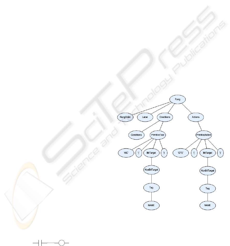
AZ
Figure 1: A simple ladder logic rung.
The Goal Non-Terminal. The topmost grammar
rule is called the goal non-terminal. This is the first
rule specified in the list of grammar rules that make
up the formal language. It is unique because every
other non-terminal will be used as a component part
of another grammar rule, but the goal non-terminal
has no ‘parent’ rule. The set of strings that the goal
non-terminal can contain will be every possible legal
L5K program, including the stream of tokens
generated by lexing a legal program.
3.2.2 Abstract Syntax Trees
The data structure created by the parser that contains
all the information about which grammar rules were
used to parse a program can be represented
diagrammatically by an abstract syntax tree (AST).
In an AST, the nodes between branches represent
non-terminal rules and the ‘leaves’ of the tree are
terminal tokens. The goal non-terminal is the root
node, and the branches show which non-terminal
rules can be substituted in to each other.
Figure (2) below shows a small part of an AST, a
sub-tree for the simple rung shown in figure (1).
Figure 2: Sub-tree of a simple rung.
In this subtree, the lexed output are the literal
instructions ‘XIC’ and ‘OTE’, the parentheses ‘(‘
and ‘)’ and the terminal token for both instances of
NAME, which in this case would be A and Z. Every
other node is a non-terminal, and the way in which
ICINCO 2008 - International Conference on Informatics in Control, Automation and Robotics
146
these non-terminals are structures represents the
form of the grammar rules
.
3.3 Attribute Evaluation
Attribute evaluation entails attaching rules to
grammar productions and terminals that compute
certain interesting values over syntax trees.
Computation of these values involves composing the
attribute computations for the constituents of the tree
with intermediate values passed up or down the tree
depending on what is being calculated. Ultimately,
calculated values are stored in hash trees associating
attributes with specific AST nodes. Passing down
from a parent to child node is known as ‘inheriting’
a value, and from a child to parent is called
‘synthesis’ of a value. The value passed is often then
used in another rule associated with that particular
production.
If a parent node needs a value passed up from its
child to complete a calculation then it is imperative
that the child rule is evaluated before the parent rule.
The ordering can be further complicated by
directives included by the user which force one rule
to be executed before or after another. The partial
order for the collection of these values and how they
are calculated over a structure as large as an abstract
syntax tree is critical.
3.3.1 Calculating Metrics
Attribute evaluation can be used to measure the
inherent properties of a piece of code.
The following examples will show how to
measure some basic metrics:
The number of rungs of ladder logic in a
program.
The cyclomatic complexity of a ladder logic
program.
Number of Rungs
Every time an AST node reflecting the grammar rule
RungList = RungList CommentedRung ;
is encountered, the following associated attribute
evaluation rule is executed.
RungList[0].CommentedRungCount =
RungList[1].CommentedRungCount + 1 ;
The CommentRungCount value can then be
passed up the AST to a higher level grammar rule by
synthesis. The grammar production
RoutineDefinition = 'ROUTINE' NAME
RoutineAttributes RungList
'END_ROUTINE' ;
Has the associated rule
RoutineDefinition[0].CommentedRungCount
= RungList[1].CommentedRungCount ;
This hands the value of CommentedRungCount
from the child node (RungList) to the parent
(RoutineDefinition). Once the value has been passed
higher up the tree, the value can be summed over the
number of routines, and then over the number of
programs to get the final value for the number of
rungs in a file.
Cyclomatic Complexity
Calculating the cyclomatic complexity is more
difficult. Knowing that
Cyclomatic Complexity = Number of Closed
Loops + 1
(Watson, McCabe 1996) and the number of
closed loops is essentially the number of ‘If’
statements makes this possible. But what constitutes
an ‘If’ statement in ladder logic where no such
construct is built in to the language?
The assertion made here is that if a non-trivial
condition precedes an action in a rung then that is a
closed loop. This simplest example of this is shown
in figure (1) above. This can be thought of as an If
statement in a conventional language; IF A is true
THEN execute Z.
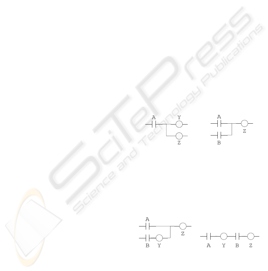
Figure 3. Figure 4.
Figure(3) and figure(4), like the example above
still contain just one IF statement. In figure(3) IF A
is true THEN execute Y AND Z; in figure(4) IF A
OR B is true THEN execute Z.
Of course it is possible to have multiple IF
statements contained within the same rung.
Figure 5. Figure 6.
Both figure(5) and figure(6) contain two IF
statements. In figure(5), IF B true THEN execute Y
AND IF A OR B true THEN execute Z; in
figure(6) IF A true THEN execute Y AND IF A
AND B are both true THEN execute Z.
CALCULATING SOFTWARE METRICS FOR LADDER LOGIC
147

Determining what is a non-trivial condition or
action is achieved by passing around Boolean flags
up and down the AST for each rung. These flags
assess whether a condition or action is trivial or not.
The attribute NonTrivialCondition is defined to be
A non-empty Condition
An Action that starts with a non-null condition
Conditions = ;
Conditions[0].NonTrivialCondition =
false ;
Conditions = Conditions
PrimitiveTest;Conditions[0].NonTrivialC
ondition = true ;
An additional flag is required for Actions (which
can contain Conditions in them).
NonTrivialTrailingCondition is true if an Action
ends with a non-null Condition.
The number of If statements is then summed
over all rungs within a routine, and to calculate the
cyclomatic complexity one is added to that total.
An example of a grammar rule, the associated
attributes and complexity calculation is shown
below.
PrimitiveAction = '['
ParallelConditions ParallelActions ']';
PrimitiveAction[0].NonTrivialCondition
=
ParallelConditions[1].NonTrivialConditi
on /\
ParallelActions[1].NonTrivialCondition
;
PrimitiveAction[0].NonTrivialTrailingCo
ndition =
ParallelActions[1].NonTrivialTrailingCo
ndition ;
IF
ParallelConditions[1].NonTrivialConditi
on /\
~ParallelActions[1].NonTrivialCondition
THEN PrimitiveAction[0].IfCount =
ParallelActions[1].IfCount + 1 ;
ELSE PrimitiveAction[0].IfCount =
ParallelActions[1].IfCount ;
ENDIF;
3.3.2 Reporting Metrics
A family of metrics is calculated using this method.
These include:
Lines code without blank lines and comments
Number of files *
Number of Programs *
Number of Routines *
Number of Rungs *
Number of Rungs with comments *
Cyclomatic complexity
Cyclomatic complexity of the largest rung *
Mean Cyclomatic complexity per rung *
PrimitiveTest Count *
Maximum number of PrimitiveTests on a rung *
Mean number PrimitiveTests per rung *
Decision density
Ladder instruction occurrence *
Motion instruction occurrence *
Halstead unique operators
Halstead unique operands
Halstead operator occurrence
Halstead operand occurrence
Halstead program length
Halstead program vocabulary
Halstead program volume
Halstead program difficulty
Halstead program effort
Halstead bug prediction
These are standard software engineering metrics
except the starred metrics which are ladder logic
analogues. As well as these metrics, the location in
the source code of the rung with the biggest
cyclomatic complexity and also the largest number
of PrimitiveTests is also reported.
The metrics reporting engine collects the
required base information at different points in the
hierarchy: routine, program (a collection of
routines), controller (a collection of programs) and
system level (a collection of files/controllers). The
necessary calculations are then performed and the
metrics are collated in to multiple reports of
different formats (.txt and .xml files).
4 RESULTS
The metrics tool has been used to analyze
production code from automotive OEMs. Just under
200000 lines of source code were analyzed – the tool
took about 30 seconds to run. The results that it has
produced have been very interesting. Some of the
most notable are:
Mean cyclomatic complexity per rung is in the
range 1.1 – 1.6. This seems reasonable,
averaging just slightly over 1 decision per rung.
The maximum cyclomatic complexity found for
any rung was 31. This level of complexity
found on one rung means the program is harder
to conceptualize than it needs to be and that to
ICINCO 2008 - International Conference on Informatics in Control, Automation and Robotics
148

enhance the readability of the routine for other
programmers and users, this complicated rung
should be split in to several smaller, simpler
rungs.
The mean number of PrimitiveTests per rung is
in the range 2 – 4.
The maximum number of PrimitiveTests found
on a rung is 89. This is a very large value and
makes navigating a program difficult as that
amount of information cannot easily be fitted on
to a standard monitor sized screen even when
zoomed out. Action should certainly be taken to
address this problem.
For a set of 729 routines, the mean cyclomatic
complexity was 31.37 but the median was 16,
indicating that the majority of the routines are
relatively small, but some of the bigger ones get
quite large. The programmer should re-examine
the more complex routines to see if a) there is a
better way to implement the logic so that the
functionality is equivalent but the routines less
complex, b) that the complex routines can be
split in to multiple simpler routines
A sample of some metrics report output can be
found in the appendix.
5 CONCLUSIONS
There is a need to evaluate the quality of code
produced for industrial control systems. Using the
DMS® Software Engineering Toolkit, tools have
been developed that use attribute evaluation over an
abstract syntax tree to compute metrics that have
been in common use in more conventional
programming languages for nearly thirty years.
It is hoped that appropriate use of these tools will
help programmers produce clear and concise code,
will allow project managers to make better decisions
concerning their code based upon the numerical
evidence gleaned from the tool. Industrial partners
willing to trial these tools within are being actively
sought after.
ACKNOWLEDGEMENTS
My most sincere thanks to Dr. Ira Baxter for his
guidance and patient tuition on how to use the
DMS® toolkit.
Both the Engineering and Physical Sciences
Research Council and Rockwell Automation for
funding this research.
Dr. Vivek Hajarnavis and Larry Akers for their
valuable encouragement and feedback.
REFERENCES
IEEE Standard 610.12, 1990, IEEE Standard Glossary of
Software Engineering Terminology
A. Phukan, M. Kalava and V. Prabhu, 2005. Complexity
metrics for manufacturing control architectures based
on software and information flow. Computers &
Industrial Engineering 49 1-20
G. Frey, 2002, Software Quality in Logic Controller
Programming, Proceedings of the IEEE SMC
M. B. Younis and G. Frey, 2007. Software Quality
Measures to Determine the Diagnosability of PLC
Applications. Proceedings of the IEEE ETFA.
Thomas McCabe, 1976, A Complexity Measure, IEEE
Transactions on Software Engineering, Volume 2, No
4, pp 308-320
F. Danielsson, P. Moore, P Eriksson, 2003, Validation,
off-line programming and optimization of industrial
control logic, Mechatronics 13 571-585
I. D. Baxter, C. Pidgeon, M. Mehlich, 2004, DMS®:
Program Transformations For Practical Scalable
Software Evolution, Proceedings of the IEEE
International Conference on Software Engineering
A. Watson, T McCabe, 1996, Structured Testing: A
Testing Methodology Using the Cyclomatic
Complexity Metric, NIST Special Publication 500-235
APPENDIX
FILE
C:/RSLogix5000/l5k_files/Z24_PLC1.L5K
55134 lines of source.
54783 lines of l5k code without blank
lines and comments.
20 programs.
232 routines.
7407 rungs.
Aggregate cyclomatic complexity: 7653
Mean cyclomatic complexity: 32.99
Median cyclomatic complexity: 21.00
Cyclomatic complexity of the largest
rung: 31
Position of rung with maximum
cyclomatic complexity, occurs @ line:
54494
Mean Cyclomatic complexity per rung:
1.03
PrimitiveTest Count: 19025
Maximum number of PrimitiveTests of any
rung in the Controller: 30
Decision density: 5.01
Halstead unique operators: 53
Halstead unique operands: 1865
CALCULATING SOFTWARE METRICS FOR LADDER LOGIC
149

Halstead operator occurrence: 37222
Halstead operand occurrence: 108478
Halstead program length: 145700
Halstead program vocabulary: 1918
Halstead program volume: 1588914.89
Halstead program difficulty: 1541.38
Halstead program effort: 2449115919.79
Halstead bug prediction: 529.64
PROGRAM MainProgram @ line 59508
7027 lines of l5k code without blank
lines and comments.
139 routines.
Number of Rungs: 2713
Aggregate cyclomatic complexity: 4535
Mean cyclomatic complexity: 32.63
Median cyclomatic complexity: 4.00
Mean Cyclomatic complexity per rung:
1.67
Cyclomatic complexity of the largest
rung: 26
Position of rung with maximum
cyclomatic complexity, occurs @ line:
63750
PrimitiveTest Count: 10989
Mean number PrimitiveTests per rung:
4.05
Maximum number of PrimitiveTests on a
rung: 81
Position of rung with maximum number
of PrimitiveTests, occurs @ line: 59702
Decision density: 0.65
Halstead unique operators: 67
Halstead unique operands: 955
Halstead operator occurrence: 18365
Halstead operand occurrence: 56269
Halstead program length: 74634
Halstead program vocabulary: 1022
Halstead program volume: 746129.49
Halstead program difficulty: 1973.83
Halstead program effort:
1472735785.88
Halstead bug prediction: 248.71
ROUTINE S_Dcu @ line 20278
410 lines of l5k code without blank
lines and comments.
Number of Rungs: 102
Number of Rungs with comments: 102
Cyclomatic complexity: 114
Cyclomatic complexity of the largest
rung: 9
Position of rung with maximum
cyclomatic complexity, occurs @ line:
20675
Mean Cyclomatic complexity per rung:
1.12
PrimitiveTest Count: 167
Maximum number of PrimitiveTests on
a rung: 11
Position of rung with maximum number
of PrimitiveTests, occurs @ line: 20675
Mean number PrimitiveTests per rung:
1.64
Decision density: 0.28
Ladder instruction occurrence: 380
Motion instruction occurrence: 10
Halstead unique operators: 31
Halstead unique operands: 183
Halstead operator occurrence: 442
Halstead operand occurrence: 1251
Halstead program length: 1693
Halstead program vocabulary: 214
Halstead program volume: 13106.30
Halstead program difficulty: 105.96
Halstead program effort: 1388731.04
Halstead bug prediction: 4.37
ICINCO 2008 - International Conference on Informatics in Control, Automation and Robotics
150
