
OPTIMISING
A FLYING ROBOT
Controller Optimisation using a Genetic Algorithm on a Real-World Robot
Benjamin N. Passow
Institute of Creative Technologies, De Montfort University, The Gateway, LE1 9BH Leicester, U.K.
Mario Gongora
Centre for Computational Intelligence, De Montfort University, The Gateway, LE1 9BH Leicester, U.K.
Keywords:
Genetic algorithm, robot, helicopter, PID, control.
Abstract:
This work presents the optimisation of the heading controller of a small flying robot. A genetic algorithm
(GA) has been used to tune the proportional, integral, and derivative (PID) parameters of the helicopter’s
controller. Instead of evaluating each individual’s fitness in an artificial simulation, the actual flying robot has
been used. The performance of a hand-tuned PID controller is compared to the GA-tuned controller. Tests on
the helicopter confirm that the GA’s solutions result in a better controller performance. Further more, results
suggest that evaluating the GA’s individuals on the real flying robot increases the controller’s robustness.
1 INTRODUCTION
Flying Robots capable of vertical take off and land-
ing (VTOL) including miniature flying robots (MFR),
have gained a strong research interest within the last
decade (Bouabdallah et al., 2007). The manoeuvra-
bility of these robots presents new and exciting possi-
bilities for research, industry, military, and search and
rescue services.
Helicopters are very versatile in their manoeuvra-
bility and have a number of advantages over other
robotic platforms. However, one of the biggest disad-
vantages is the fact that they are nonlinear and highly
unstable systems, very sensitive to external distur-
bances (Bagnell and Schneider, 2001), and are there-
fore difficult to control. A simple manoeuvre like
hovering requires constant control feedback from the
pilot, similar to what a human needs to do when stand-
ing and balancing on a ball. Because of the char-
acteristics mentioned above, a controller for an au-
tonomous helicopter must be fast in computing the
control response. Active control is traditionally im-
plemented using a combination of proportional, inte-
gral, and derivative (PID) control methods (Skogestad
and Postlethwaite, 1996). Such a conventional con-
troller is fast and works well for many control appli-
cations and therefore has been chosen for this work.
Classical PID control techniques have been used be-
fore to stabilise an autonomous helicopter (Puntunan
and Parnichkun, 2002; Sanchez et al., 2005). The dif-
ficulty in applying this method is the right choice of
control parameters, and in our case the limited pay-
load of the helicopter for the necessary processing
hardware.
Genetic algorithms (GA) have been used be-
fore for identification and optimisation of PID con-
trol parameters (Perhinschi, 1997). A simulator
of the corresponding system is very often used in
order to evaluate the individual’s fitness within a
GA (De Moura Oliveira, 2005). This artificial model
requires extensive knowledge about the system being
controlled, or the system needs to be identified to cre-
ate the model. Rather than optimising the controller
using a simulation of the system we have explored
the possibility of using the robot itself for the opti-
misation and evaluation of the controller. By doing
so, the model identification becomes implicit and the
system becomes more accurate, more realistic, thus
overcoming the limitation of simulated optimisations
where the quality of the solution is restricted by the
quality of the simulator.
151
N. Passow B. and Gongora M. (2008).
OPTIMISING A FLYING ROBOT - Controller Optimisation using a Genetic Algorithm on a Real-World Robot.
In Proceedings of the Fifth International Conference on Informatics in Control, Automation and Robotics - RA, pages 151-156
DOI: 10.5220/0001496901510156
Copyright
c
SciTePress
2 BACKGROUND
The growth of interest and investigations in UAVs
includes vehicles capable of vertical take off
and landing (VTOL) and miniature flying robots
(MFR) (Bouabdallah et al., 2007). Such vehicles
are very versatile in their manoeuvrability and thus
present an advantageous robotics platform for re-
search in new areas.
Ludington et al. use the GTMax helicopter plat-
form for complex navigational tasks, pattern recog-
nition and test runs involving searching for a certain
pattern on a building and then identifying windows
and doors (Ludington et al., 2006). The achieve-
ment of this work shows what can be done using a
large autonomous helicopter platform. For a small
and light weight indoor helicopter the restrictions de-
mand other approaches.
In general, helicopters have 3 rotational degrees
of freedom (DOF), called pitch, roll and yaw, as well
as 3 translational DOF called up/down, left/right and
forwards/backwards. These outputs are controlled by
four inputs, the amount of lift with the speed and/or
collective pitch of the rotor, the heading with the anti-
torque system or the differential of two rotors, and
the pitch and roll rotational angles which are in turn
controlled by adjusting the rotor blades’ plane angles.
For more information the reader is referred to Coyle,
1996.
The helicopter used in this work is a Twister Bell
47 small indoor helicopter model. It is a coaxial rotor
helicopter with twin counter rotating rotors with fixed
collective pitch and 340 mm. span, driven by two high
performance direct current motors and two servos to
control rotor blades’ plane angles. The weight of the
helicopter in its original state is approximately 210
grams and it can lift up to 120 grams.
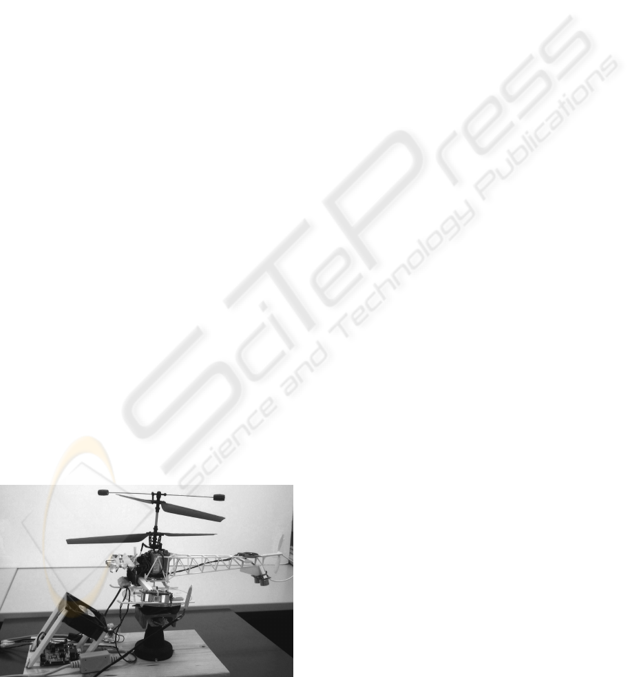
A helicopter’s engine causes a torque effect on the
Figure 1: Experimental setup: helicopter strapped to turn
table, ready for the GA tuning.
helicopter. The two engines and rotors of this dual
coaxial rotor helicopter turn in opposite directions,
creating opposite torque effects that cancel each other
out. If one rotor’s speed is reduced whilst the other’s
speed is increased by an identical amount, the heading
will change whilst the amount of lift is maintained.
Helicopter controllers have been successfully im-
plemented using a variety of methods, including clas-
sical PID control (Puntunan and Parnichkun, 2002).
Puntunan and Parnichkun introduce a heading direc-
tion and floating height PD-controller for a single ro-
tor helicopter. This confirms that classical control
techniques can be used to control helicopter inputs.
The design and evaluation of the controller is of-
ten done on a mathematical model and simulation.
Shim et al. present a study of three control design
methodologies for an autonomous helicopter (Shim
et al., 1998). The controllers are designed and eval-
uated on an artificial model based on aerodynamics
models.
Sanchez et al. (Sanchez et al., 2005) introduce
an unmanned helicopter control system combining
a Mamdani type fuzzy logic controller (Mamdani,
1974) with PID controllers. The design and evalu-
ation is done using a complex mathematical model.
The system is only tested via simulation for hovering
and slow velocities, but showed good performance.
Perhinschi (Perhinschi, 1997) used GAs to iden-
tify the gain parameters of linear differential equa-
tions which are used to stabilise and control a heli-
copters longitudinal channel. The GAs used a lin-
earised model of a helicopter and the controller per-
formance is not tested in simulation nor on a real he-
licopter.
3 CONTROL ARCHITECTURE
The model helicopter has four actuators to enable the
control of all six DOF. There are two motors which
independently control the speed of each rotor, giving
combined control over altitude and yaw. Two servos
control the lower rotor blades’ plane angles for pitch
and roll control. For autonomy, all of these actuators
need to be controlled by a microprocessor. As only
the heading controller is tuned in this work, only that
part of the system is described in detail.
A digital compass is used to determine the heli-
copter’s heading. The sensor is attached to the tail
of the helicopter to increase the distance to the mo-
tors and thus reduce the interference they have on the
sensor. The sensor is connected to a microchip PIC
microcontroller. The microcontroller handles all on-
board computation, sensor inputs, motor outputs, and
ICINCO 2008 - International Conference on Informatics in Control, Automation and Robotics
152
serial communication used to transfer information to
and from the host computer on which the GA is run-
ning.
The control application running on the microcon-
troller reads all sensors, calculates all four PID control
responses, one for each control input, and then sends
the overall control responses to the actuators. In this
system there are 13 control cycles executed each sec-
ond.
The PID controller is implemented straightfor-
wardly by first multiplying the proportional part with
the proportional gain (PGain). Then the integral part
is calculated, multiplying the integral gain (IGain)
with the previous error which is limited by an positive
and negative limit (IMax and IMin). The derivative
part is computed multiplying the change of error with
the derivative gain (DGain). Finally all three results
are added up to get the final control response.
There are a number of existing techniques for tun-
ing PID controllers (De Moura Oliveira, 2005). Even
when tuning a PID controller by hand, a variety of
strategies can be applied. The method used in this
work is hand tuning and has been adapted from Smith,
1979. Using this method, the parameters shown in ta-
ble 1 (Value) were identified.
Table 1: Hand tuned parameters and GA’s parameter range.
Parameter Short Value Range
Proportional gain PGain 0.30 0 - 2.00
Integral gain IGain 0.02 0 - 1.00
Integral state maximum IMax 100 0 - 400
Integral state minimum IMin -100 0 - -400
Derivative gain DGain 0.70 0 - 4.00
4 EXPERIMENTAL SETUP FOR
THE GENETIC ALGORITHM
Genetic algorithms are widely used for search and
optimisation purposes (Holland, 1975; Haupt and
Haupt, 2004). GAs are very useful for optimising
controllers (Fleming and Purshouse, 2002): this ro-
bust and flexible method can handle ill-behaved prob-
lem domains as well as noise and can be used for
multi-objective optimisation.
Rather than using a simulator with the GA, we
optimise the controller on the real flying robot. The
system setup is shown in figure 1. It shows the dual
rotor helicopter attached to a ball bearing supported
turn table, restricted to turn up to 90
o
and -90
o
de-
grees from its middle position at 0
o
. The fan is used
for cooling down the helicopter’s motors and the em-
bedded system in between tests of individuals. Each
test takes about 20 seconds with an additional 20 sec-
onds to cool the system down. The fan is switched
off while individuals are evaluated. Each individual
is tested by automatically perturbing the helicopter to
each side and analysing the controller’s reaction. This
setup in combination with the GA running on a host
computer, enables the automatic implementation and
evaluation of individuals and thus the execution of the
GA on the real robot without any human intervention.
The GA running on the host computer is configured
as follows:
Solution Encoding. Based on the hand tuned con-
trollers parameters (table 1), parameter ranges have
been chosen and are shown in table 1. The chromo-
some consists of 5 integer values within that range.
The gain parameters are encoded in steps of one hun-
dredth, and the two integral state limits are encoded
in 16 steps of 25.
Initial Population. The initial population is created
in a random manner, choosing each chromosome ran-
domly within the limits previously defined in table 1.
The population size of 20 is chosen small enough to
have a fast evaluation of each generation while pro-
viding enough individuals to maintain variety.
Evaluation Function. The evaluation function needs
to evaluate each individual on the real helicopter. The
phenotype of an individual is the real helicopter con-
troller where the controller’s parameters are based on
the individual’s chromosome. The evaluation func-
tion is shown in equation 1.
e =
189
∑
t=1
(h
t
− s)
2
(1)
where e is the measure of error, t is time, 189 is the
last control cycle of the evaluation, h
t
is the heading
at time interval t, and s is the setpoint. The fitness
of an individual is inversely proportional to the mea-
sure of error. Squaring the error on each time interval
increases selective pressure on large errors and helps
find better solutions more quickly.
The GA program runs on the host computer. To
evaluate an individual, its chromosome is sent to the
helicopter’s embedded system using a direct serial
connection. The helicopter uses the received chromo-
some as the new control parameters, starts the motors
and the controller reacts on the heading error based
on these new parameters. While the controller and
its evaluation are active, the heading sensor data is
sent back to the host computer. In order to test the
controller’s performance on a given error, the heli-
copter is initially and automatically perturbed by 90
o
to the set point, by driving the two rotors with dif-
ferent power levels. The helicopter turns but cannot
go beyond 90
o
as the experimental setup physically
OPTIMISING A FLYING ROBOT - Controller Optimisation using a Genetic Algorithm on a Real-World Robot
153
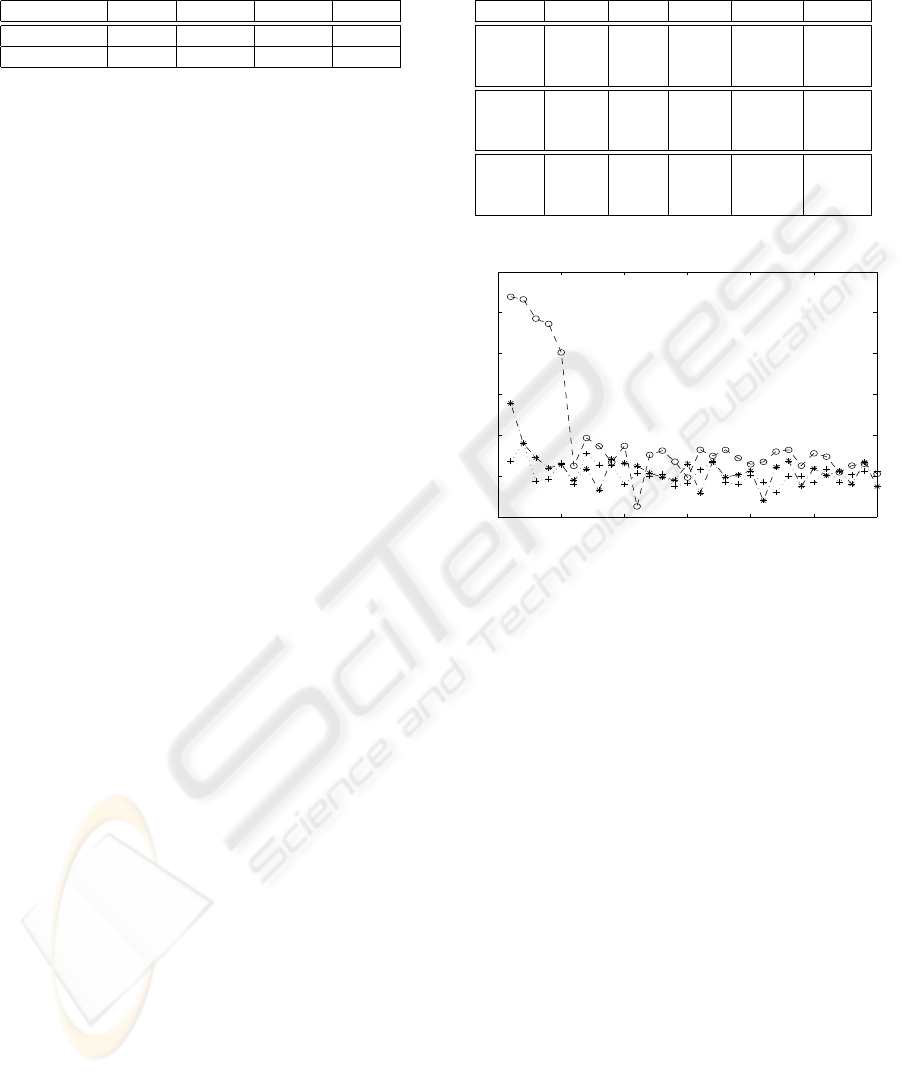
Table 2: Min, mean, max, and standard dev. of measure of
error of 12 tests of hand tuned and best GA individuals.
Min Mean Max StD
Hand tuned 95080 114351 134705 13556
GA tuned 45584 75850 88306 11233
blocks it. At this point the controller starts acting and
is being evaluated. After 92 control cycles the eval-
uation and controller are paused and the helicopter is
perturbed -90
o
, into the opposite direction. Finally the
controller and its evaluation are started again.
Selection. The selection is based on the fitness com-
bined with random probability, similar to the roulette
wheel strategy, but without the possibility of choos-
ing an individual more than once. With this method
in place, every individual could be chosen for the next
generation although fitter individuals are more likely
to be selected.
Genetic Operators. The individuals selected for the
next generation are copied or changed using crossover
or mutation operators. The best individual is always
copied to the next generation. This process is also
known as elitism. Altogether 20% of the old popu-
lation are copied based on the probabilistic selection.
These individuals are not changed at all.
Crossover is applied by taking the average of an
individual’s chromosome and the chromosome of the
individual next in the probabilistic selection list. 40%
of the next generation are the offspring of the previous
generation’s individuals.
The mutation operator is the source for new va-
riety. It uses a probabilistic approach whereby the
chance of a small mutation taking place is higher than
that of big mutation taking place. This method has
been applied to 40% of the individuals and on each of
its loci.
Termination Criteria. The GA is terminated after
the 30th generation. In order to investigate the GA’s
behaviour no minimum fitness has been defined on
which the GA would terminate.
5 RESULTS AND ANALYSIS
The GA on the real helicopter platform has been run
without the need for manual interaction with the sys-
tem. Three complete runs have been conducted and
the results are shown and discussed now.
With a population size of 20, running for 30 gen-
erations, the GA evaluates 600 individuals from a
search space of over 2 billion. Each individual re-
quires about 20 seconds for evaluation and 20 seconds
Table 3: Solutions of 3 best individuals of 3 independent
GA runs plus measure of error.
PGain IGain IMin IMax DGain Error
0.89 0.98 200 0 2.68 45237
0.83 0.43 75 0 3.13 59385
0.86 0.56 75 0 2.97 59886
0.93 0.34 75 0 3.67 52080
1.08 0.15 0 0 3.95 55174
1.05 0.49 25 0 3.73 56036
0.96 0.69 275 0 3.20 48092
0.93 0.00 0 0 3.15 51827
1.12 0.81 325 0 3.07 53210
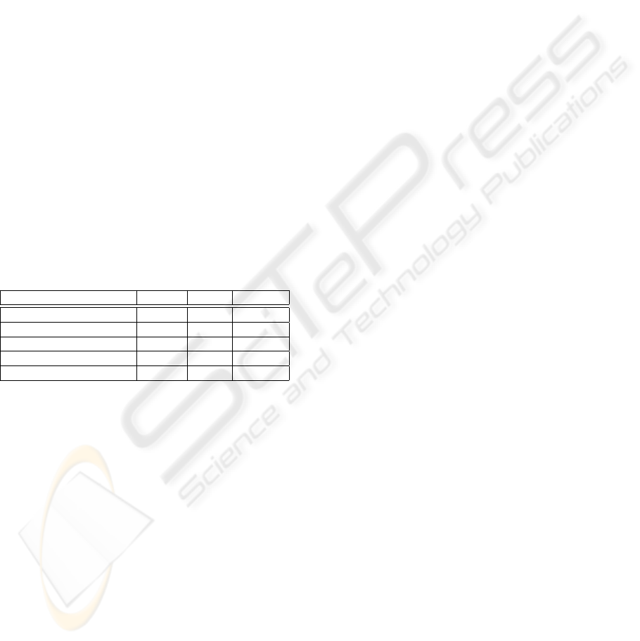
0 5 10 15 20 25 30
0.4
0.6
0.8
1
1.2
1.4
1.6
x 10
5
Generations
Measure of error
Figure 2: Best individual’s measure of error of each gener-
ation in 3 independent GA runs.
for the helicopter to cool down, thus the overall time
for one GA to finish is about 6 hours 40 minutes.
Elitism is the method of always copying the best
individual to the next generation. In simulations this
often means a positive or at least zero increase in fit-
ness. Every generation’s best individual’s measure of
error from 3 GA runs is shown in figure 2. Although
elitism is used in this work, the fitness of the best indi-
viduals of every generation fluctuates and sometimes
even gets worse rather than showing a monotonic in-
crease. The cause for this is the deviation when re-
evaluating an individual. Retesting two individuals
12 times showed a standard deviation of 11233 and
13556 for the measure of error (table 2). This shows a
critical and important difference between using simu-
lated models with an unnatural consistency compared
to working with the real system.
Usually, when there is a suitable solution found
within a simulated system, such as in generation 11
in figure 2, it is not worth continuing the GA. Using
the real world system, continuing the GA helps en-
sure the consistency of the final solutions. Noise and
uncertainties in the system make the GA not converge
to one specific solution but to a more robust solution.
ICINCO 2008 - International Conference on Informatics in Control, Automation and Robotics
154
0 50 100 150 200
−100
−80
−60
−40
−20
0
20
40
60
80
100
Time [control cycles]
Error [degrees]
Figure 3: Hand tuned PID controller response to heading
perturbed by 90
o
at t=0 and -90
o
at t=92. Composite of 12
individual tests.
Table 3 lists the three best solutions of the three in-
dependent GA runs together with their measure of er-
ror. The proportional gain value is similar in all three
GA runs, converging to a good value region. The
small difference between the values indicates that this
parameter has a high impact on the controller’s perfor-
mance. The derivative gain parameter did converge to
a smaller region of values too, but not as restricted as
the proportional gain. On the other hand, the integral
gain together with the integral state minimum value
seem not to be as important for the fitness as they are
not forced into a specific region of values by the selec-
tive pressure. In contrast, it is quite obvious that the
integral state maximum was forced to be zero. These
results show that the system is not symmetrical. They
show that the helicopter controller needs more gain in
one direction than in the other. This could be caused
by a variance in the motors’ efficiency factors, heli-
copter asymmetry, or other causes.
Out of 3 GA runs we chose the one with the least
fit final individual. From this GA we used the fittest
individual of the last generation to compare it to the
hand tuned controller. The individual has a PGain
of 0.92, IGain of 0.12, IMin of 250, IMax of 0, and
DGain of 3.64. Figure 3 depicts the response graph
of the hand tuned PID controller perturbed by 90
o
at
t = 0 and -90
o
at t = 92 as a composite of 12 indi-
vidual tests. Figure 4 shows the response graph of the
GA tuned PID controller. Figure 5 presents the plot of
the mean of these 12 tests, for both the GA and hand
tuned controllers.
These graphs confirm that the GA tuned controller
performs better than the hand tuned controller. After
the first and positive perturbation, in general the hand
tuned controller does overshoot the setpoint slightly
whereas the GA tuned controller does not. Further-
more, the GA tuned controller reaches the set point
quicker and maintains it more accurately. For the
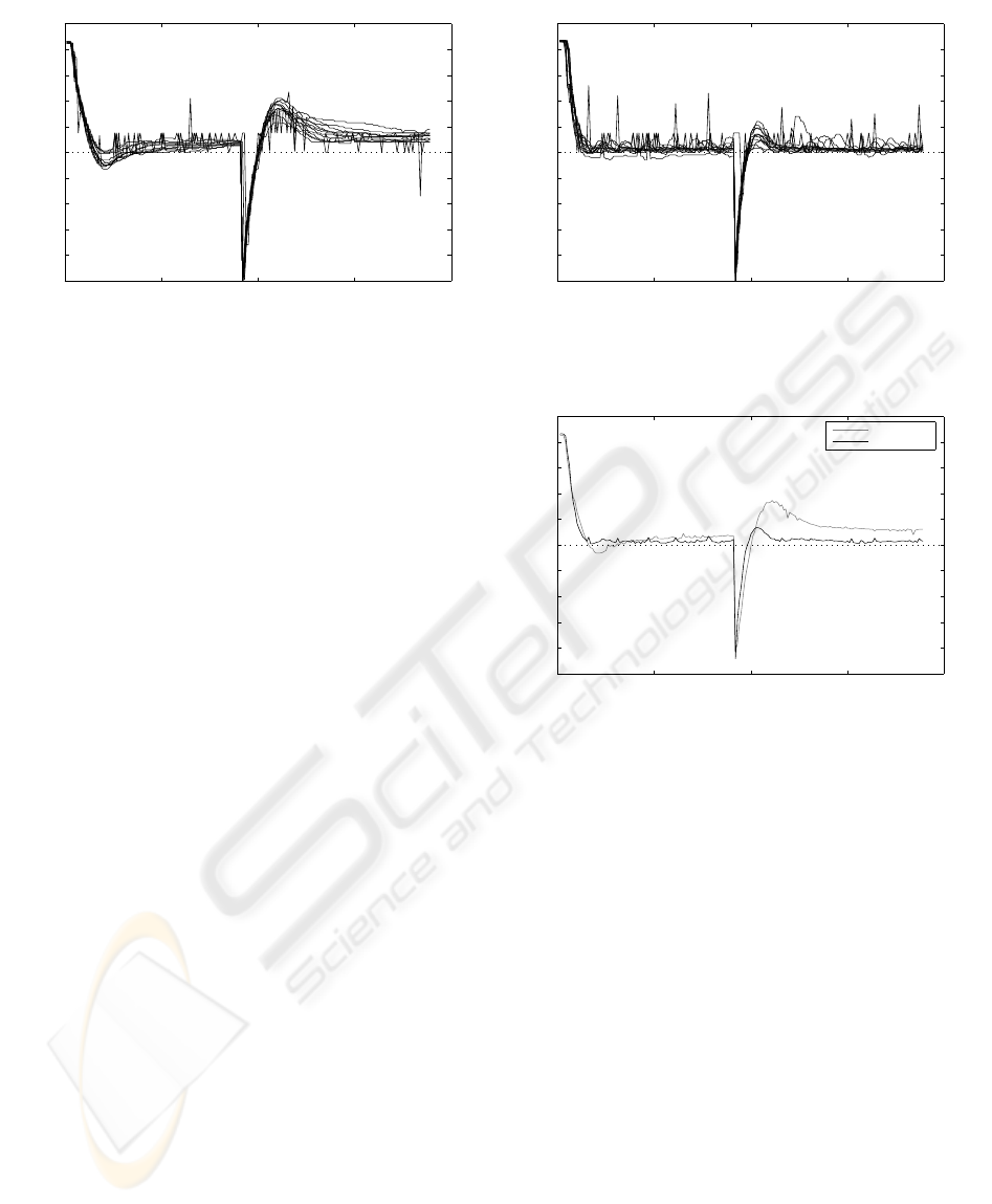
0 50 100 150 200
−100
−80
−60
−40
−20
0
20
40
60
80
100
Time [control cycles]
Error [degrees]
Figure 4: GA tuned PID controller response to heading per-
turbed by 90
o
at t=0 and -90
o
at t=92. Composite of 12
individual tests.
0 50 100 150 200
−100
−80
−60
−40
−20
0
20
40
60
80
100
Time [control cycles]
Error [degrees]
Hand tuned
GA tuned
Figure 5: GA (black) and hand tuned (gray) PID controllers
response to heading perturbed by 90
o
at t=0 and -90
o
at
t=92. Mean of 12 individual tests for each controller.
second and negative perturbation, in general the GA
tuned controller has less overshoot, approaches the set
point quicker, and maintains it more accurately.
The measure of error from all 12 tests with
the hand tuned and GA tuned controllers has been
recorded and the results are presented in table 2. Over
all 12 tests, based on the measure of error, the hand
tuned controller performed in average 50% worse
than the GA tuned controller.
It is quite normal in a real world system that run-
ning the same experiment again, evaluating the same
individual again, results in a slightly different out-
come. The standard deviation for the 12 hand tuned
and the 12 GA tuned controller evaluations is 13556
and 11233 respectively (table 2). This variation of
results is caused by noise everywhere within the sys-
tem. Due to the natural uncertainties of real systems,
the GA cannot converge to an absolute optimal solu-
tion; rather we have observed that it converges to a
robust approximate optimum that can cope with un-
certainties and noise.
OPTIMISING A FLYING ROBOT - Controller Optimisation using a Genetic Algorithm on a Real-World Robot
155

6 CONCLUSIONS
In this work we introduced a controller optimisation
methodology based on genetic algorithms running on
a real flying robot. A GA has been used to tune the
parameters of a PID controller using the real robot
rather than a simulator to evaluate the individuals.
When the evaluation of GA individuals is done in
a simulator, the performance of the final solution that
the GA can find, can only be as good as the accu-
racy of the model used for the simulation permits. We
proposed and presented a GA which evaluated the in-
dividuals on a real robot, which made implicit the for-
mal model identification.
Furthermore, we presented the results of three GA
runs indicating that its behaviour differs to the be-
haviour often seen on simulated systems. No mono-
tonic increase in fitness is exhibited by the algo-
rithm, although elitism was used. Additionally, re-
evaluating the same GA tuned individual 12 times
manifested a deviation, owing to the real system not
being as artificially consistent as a simulator, and thus
the GA converging to a more robust controller rather
than to a particular optimal solution.
In order to confirm the GA’s ability to optimise
a controller on the complex real flying robot, the best
control parameters the GA found have been compared
with previously hand tuned control parameters. The
performance of 12 individual tests with each con-
troller was compared, and confirmed that the real ex-
ecution GA found better and more robust solutions.
7 FUTURE WORK
In future work we will use the information from the
GA to identify the robot’s characteristics, which may
be useful to create a very accurate model of it. Based
on the individuals’ parameters and using the sensor
data from the robot we aim to identify the system for-
mally.
With the formal model it may be possible to im-
plement a simulator for the helicopter. At that point a
comparison of two GAs can be conducted, one using
a simulation and the other using the real robot for the
evaluation of individuals.
ACKNOWLEDGEMENTS
We would like to thank Prof. Andrew Hugill, Director
of the Institute of Creative Technologies, De Montfort
University, for his support of this research project.
REFERENCES
Bagnell, J. and Schneider, J. (2001). Autonomous he-
licopter control using reinforcement learning policy
search methods. volume 2.
Bouabdallah, S., Becker, M., and Siegwart, R. (2007).
Autonomous miniature flying robots: coming soon!-
research, development, and results. Robotics & Au-
tomation Magazine, IEEE, 14(3):88–98.
Coyle, S. (1996). The art and science of flying helicopters.
Arnold, Hodder Headline Group.
De Moura Oliveira, P. (2005). Modern heuristics review for
pid control systems optimization: A teaching experi-
ment. In Proceedings of the 5th International Confer-
ence on Control and Automation, pages 828–833.
Fleming, P. and Purshouse, R. (2002). Evolutionary algo-
rithms in control systems engineering: a survey. Con-
trol Engineering Practice, 10(11):1223–1241.
Haupt, R. and Haupt, S. (2004). Practical Genetic Algo-
rithms. Wiley-Interscience.
Holland, J. H. (1975). Adaptation in Natural and Artificial
Systems: An Introductory Analysis with Applications
to Biology, Control and Artificial Intelligence. Uni-
versity of Michigan Press.
Ludington, B., Johnson, E., and Vachtsevanos, G. (2006).
Augmenting uav autonomy. Robotics & Automation
Magazine, IEEE, 13(3):63–71.
Mamdani, E. H. (1974). Application of fuzzy algorithms for
simple dynamic plant. IEE Proceedings on Control
Theory and Applications, 121:1585 – 1588.
Perhinschi, M. (1997). A modified genetic algorithm for
the design of autonomous helicopter control system.
In Proceedings of the AIAA Guidance, Navigation and
Control Conference, pages 1111–1120.
Puntunan, S. and Parnichkun, M. (2002). Control of head-
ing direction and floating height of a flying robot.
In Industrial Technology, 2002. IEEE ICIT’02. 2002
IEEE International Conference on, volume 2, pages
690–693, Bangkok, Thailand.
Sanchez, E., Becerra, H., and Velez, C. (2005). Combin-
ing fuzzy and pid control for an unmanned helicopter.
In Annual Meeting of the North American Fuzzy In-
formation Processing Society, pages 235–240, Unidad
Guadalajara, Mexico.
Shim, H., Koo, T., Hoffmann, F., and Sastry, S. (1998).
A comprehensive study of control design for an au-
tonomous helicopter. In Decision and Control, 1998.
Proceedings of the 37th IEEE Conference on, vol-
ume 4, pages 3653–3658, Tampa, Florida, USA.
Skogestad, S. and Postlethwaite, I. (1996). Multivariable
Feedback Control: Analysis and Design. Wiley.
Smith, C. (1979). Fundamentals of Control Theory, vol-
ume 86. Chemical Engineering.
ICINCO 2008 - International Conference on Informatics in Control, Automation and Robotics
156
