
A DISTRIBUTED HARDWARE-SOFTWARE ARCHITECTURE FOR
CONTROL AN AUTONOMOUS MOBILE ROBOT
Ricardo S. Britto, Andre M. Santana, Anderson A. S. Souza
Adelardo A. D. Medeiros and Pablo J. Alsina
Department of Computating Engineering and Automation, UFRN, Natal, Brazil
Keywords:
Control Architecture, Autonomous Mobile Robot, Hybrid Deliberative-Reactive Paradigm, CAN Bus.
Abstract:
In this paper, we introduce a hardware-software architecture for controlling the autonomous mobile robot
Kapeck. The Kapeck robot is composed of a set of sensors and actuators organized in a CAN bus. Two em-
bedded computers and eigth microcontroller-based boards are used in the system. One of the computers hosts
the vision system, due to the significant processing needs of this kind of system. The other computer is used
to coordinate and access the CAN bus and to accomplish the other activities of the robot. The microcontroller-
based boards are used with the sensors and actuators. The robot has this distributed configuration in order
to exhibit a good real-time behavior, where the response time and the temporal predictability of the system
is important. We adopted the hybrid deliberative-reactive paradigm in the proposed architecture to conciliate
the reactive behavior of the sensors-actuators net and the deliberative activities required to accomplish more
complex tasks.
1 INTRODUCTION
The control architecture of an autonomous mobile
robot aims qualify the vehicle for operating in its en-
vironment using its computational and physical re-
sources. An instance of control architecture must
guarantee the accomplishment of its own tasks in a
robust-stable way. There are many proposed architec-
tures, but there is not a definitive paradigm that imple-
mentates all the functionalities required (Medeiros,
1998).
The more representative paradigms are the hi-
erarchic, reactive and hybrid (deliberative-reactive)
paradigms. In the literature, we can find several ex-
emples of classical control architectures: NASREM,
Subsumption, AuRa, SFX, Saphira and TCA (Mur-
phy, 2000), PyramidNet (Roisenberg et al., 2004),
SHA (Kim et al., 2003), hybrid architecture proposed
by Adouane(Adouane and Le Fort-Piat, 2004), CO-
HBRA (Heinen, 2002), Ly architecture (Ly et al.,
2004) and LAAS architecture (Alami et al., 1993).
A well projected architecture is essential for im-
plementing complex robots. It must have different
kinds of hardware and software modules. Moreover,
architecture must lead the implementation and the re-
lationship of the modules.
This work firstly specify a hardware-software ar-
chitecture for the Kapeck robot. In a second moment,
this architecture will be used to implement a con-
trol organization. Finally, an experiment was made
to demonstrate the proposed architecture.
2 HARDWARE ARCHITECTURE
The Kapeck (Figure 1) is a wheeled non-holonomic
multi-task robot. The robot has a differential locomo-
tion system. It has 1 stereo head with 2 cameras and 1
sonar belt with 8 sonars. Moreover, Kapeck has 2 ma-
nipulators with 5 degrees of liberty, but in the current
stage of the project, the manipulators modules are not
included in the proposed architecture, but the modular
feature of the architecture makes easy the inclusion of
these modules in the future.
The differential locomotion system has 2 indepen-
dent wheels with 1 DC motor each one. In addition
to the motor wheels, there are 2 free wheels, without
motors. Each motor wheel has 1 attached optical en-
coder. These optical encoders, as all encoders used in
Kapeck, generate 1024 pulses per revolution.
The stereo head has 5 motors with attached optical
encoders. There are 2 CCD cameras. These cameras
have 1024X768 per pixel max resolution. They cap-
169
S. Britto R., M. Santana A., A. S. Souza A., A. D. Medeiros A. and J. Alsina P. (2008).
A DISTRIBUTED HARDWARE-SOFTWARE ARCHITECTURE FOR CONTROL AN AUTONOMOUS MOBILE ROBOT.
In Proceedings of the Fifth International Conference on Informatics in Control, Automation and Robotics - RA, pages 169-174
DOI: 10.5220/0001498401690174
Copyright
c
SciTePress
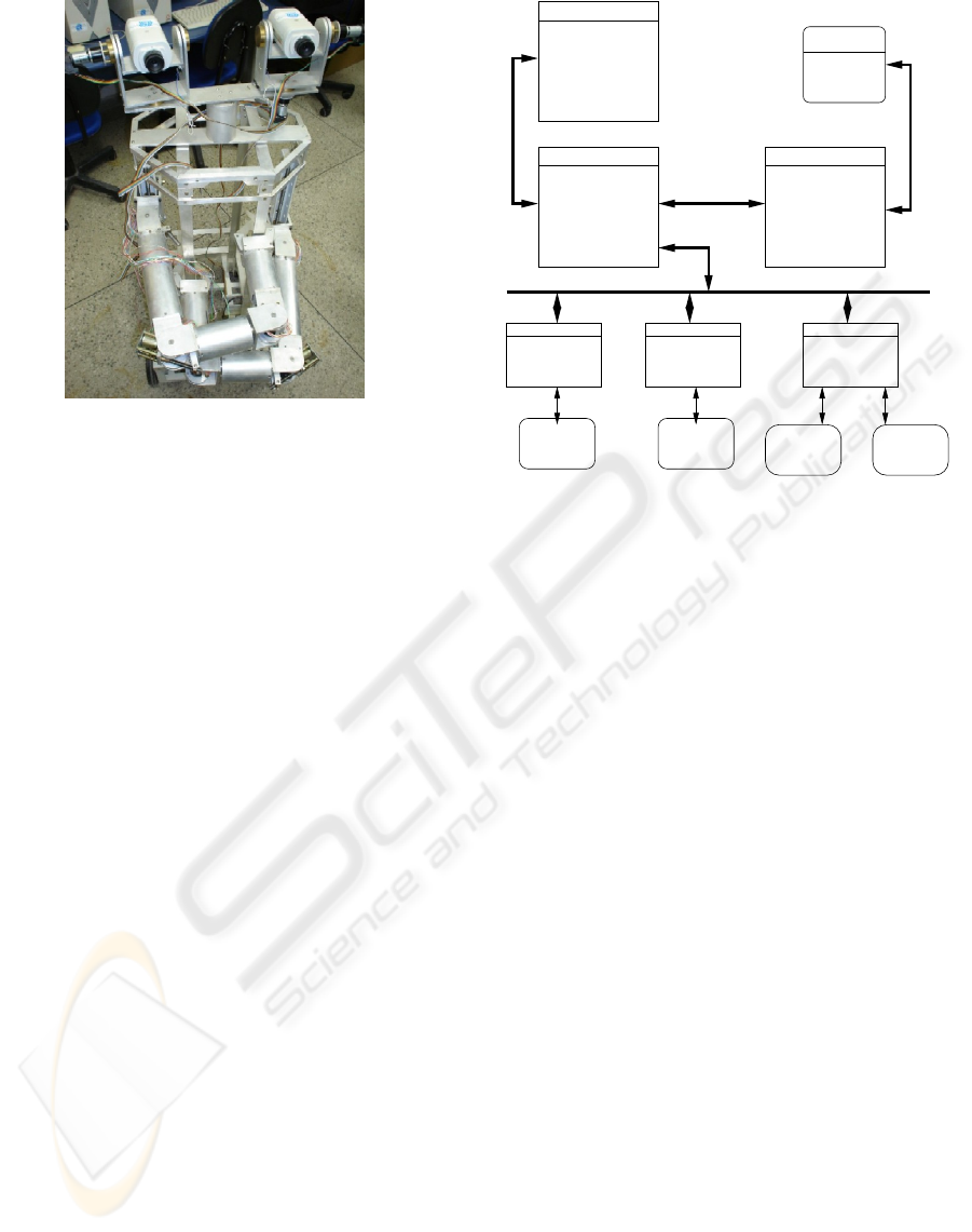
Figure 1: Robot Kapeck.
ture 30 frames per second.
All the sensors and actuators (just not cameras)
were attached to a CAN bus (Bosch, 1991). The CAN
protocol was developed in the Bosch Laboratories for
the automobilist industry, but nowadays this protocol
is used in other areas, as robotics. The CAN is very
suitable for systems with many sensors and actuators
and time constraints. This protocol can perform with
multiple masters or in master-slave mode. It supports
velocity of 1 Mbit/s in distances up 30 meters. The
maximum distance supported by CAN is 5 kilome-
ters. When used in this mode, the maximum velocity
reached in a CAN bus is 10 Kbit/s.
Due to the short sampling periods needed to ac-
cess the sensors and actuators, the presence of real
parallelism in the execution of the robot process is
needful. Thus, the proposed hardware architecture of
Kapeck (Figure 2) was developed to allow distributed
processing, using the robot 10 processors. This archi-
tecture is modular, which means the inclusion of new
hardware modules, like the software ones, is possible
and easy.
The hardware architecture is composed of 1 desk-
top computer, 2 embedded computers and 8 micro-
controlled boards. The embedded computers and mi-
crocontrolled boards are inside robot. This hardware
configuration permits the real parallel execution of the
software modules of robot.
The monitor computer (Figure 2) stays outside
Kapeck and communicates with the robot through
a wireless net (IEEE 802.11b). This computer has
the user interaction software module. This module
watches and interacts with Kapeck.
The kapeck1 computer (Figure 2) contains the
software responsible for the deliberation of the robot.
Microcontrolled
1A
Board
Encoder
and
Motor
Microcontrolled
Board
7A
...Sonar 1 Sonar 8
Pentium III 1GHz
HD IDE 20 GBHD IDE 20 GB
Linux Fedora 5Linux Fedora 5
Ethernet
Pentium III 1GHz
IEEE 802.11b
kapeck1 kapeck2
SC−60
Cameras
256 MB RAM 128 MB RAM
CAN Bus
PCI−CAN Card
Encoder
and
Motor
...
Microcontrolled
Board
PCI Frame Grabber
Athlon 64 2GHz
HD IDE 40 GB
Linux Fedora 5
Monitor
1GB RAM
Figure 2: Hardware Architecture.
It is responsible for the interface with the monitor
computer, passing to user interaction software mod-
ule information about the robotic system. Moreover,
kapeck1 can execute commands passed by monitor.
The kapeck2 computer (Figure 2) contains the
vision system (visonSis). The vision system was
placed in a separated computer due to its great com-
putational requirement. This computer communicates
with the kapeck1 using a TCP/IP Ethernet peer-to-
peer net (crossover cable).
The microcontrolled boards are responsible for
the lower control of the sensors and actuators of
Kapeck. In this way, there is a performance gain of
the robotic system due to the dedicated processing of
these boards, releasing the embedded computers to
other tasks. These boards are connected to a CAN
bus configured in master-slave mode. The CAN bus
is connected to the kapeck1 computer. Only the mas-
ter of the CAN bus, contained inside kapeck1, can
permit the access of sensors and actuators to the bus.
All the boards have a PIC 18F258. This microproces-
sor was chosen due to its embedded support to CAN
protocol . It also has PWM (Pulse Width Modulation)
generator, timers and IO ports, needful to the applica-
tions. There are 2 kinds of boards, one called motor
controller board, and another called sonar controller
board.
The motor controller board is responsible to gen-
erate the PWM signal for one motor through the PID
(Proportional Integral Derivative) control algorithm,
receiving from the high level controller the position
references or the velocity references. This board also
ICINCO 2008 - International Conference on Informatics in Control, Automation and Robotics
170

has the function of acquiring encoder measurement.
When the board is attached to a stereo head motor,
the board receives a limit switch signal. The measure-
ments are returned to kapeck1 computer. The embed-
ded PID control algorithm uses the measurements of
encoder and limit switch. The sampling period exper-
imentally chosen to the control cycle of the embedded
PID controller is 10 ms.
The sonar controller board is responsible for the
sonar functioning. It collects asynchronously sonar
measurement when kapeck1 requires such measure-
ments. The board returns to kapeck1 the range mea-
surement to the nearest obstacle.
3 SOFTWARE ARCHITECTURE
To take advantage of the distributed hardware of
Kapeck, the software modules of robot must be able
to execute in parallel way. To make it possible, this
work proposes two mechanism that permits parallel
execution of software modules. One of them is the
blackboard. The blackboards are shared memory area
that permits the interaction between software modules
(Hayes-Roth, 1985). The other mechanism is a logic
representation of the CAN bus called procCAN.
3.1 Blackboards
The blackboards are implemented by 3 C++ class
called bBoard, bBoardAtt, bBoardRe and the soft-
ware module called bBoardServer.
The bBoard class is used to create and destroy
the blackboards. This class also manages the access
to the blackboard created in mutual exclusion, using
semaphores. It is used by the system initiator mod-
ules, responsible to initiate the other software mod-
ules and create all blackboards and semaphores used
to exchange information inside the robot. All black-
board, when it is created, receives an unique identifi-
cation key (ID).
The bBoardAtt class is used to attach to existing
blackboards. This class provides the read-write prim-
itives of blackboard.
The bBoardRe class has the same methods and it
functions like the bBoardAtt, but it is used to attach
to a remote blackboard, created in another Kapeck
computer. The utilization of local and remote black-
boards is transparent to the client program, because
both classes have the same read-write methods.
The bBoardServer is a software module imple-
mented in both embedded computers. It uses in-
stances of bBoardAtt to accomplish the read-write
operations of local blackboards in the name of the re-
mote clients.
An example of architecture that uses blackboards
is the COHBRA architecture (Heinen, 2002). CO-
HBRA has a central blackboard where the software
modules share information. This approach is differ-
ent of the one used in this work, where there are many
distributed blackboards.
3.2 procCAN
This class makes transparent to the software mod-
ules the hardware features of the robot. The exis-
tence of this class makes easy hardware alterations
of the Kapeck, since it disconnects the software mod-
ules implementation from the hardware modules. The
software modules operate on the logic CAN bus, that
encapsulates the real CAN bus.
The CAN protocol has a native mechanism that
controls the simultaneous access to the bus. It uses the
CSMA/CA protocol (Carrier Sense - Multiple Access
with Collision Avoidance) (Bosch, 1991) to do that.
However, Kapeck has a node attached to the CAN
bus (kapeck1 computer) that contains many process
competing internally for the access to the CAN bus.
In this situation, the existence of a mechanism that
guarantee the mutual exclusion access of the bus is
needed, since the absence of this kind of mechanism
can create message collisions before these messages
reach the bus.
The mutual exclusion of the bus is guaranteed by
using the CAN bus in master-slave mode and using
a bus arbiter. All the methods implemented by the
procCAN class internally require the access to the real
CAN bus to the bus arbiter. If the bus is busy and a
software module requires the permition to access the
bus, the requiring module will be blocked until the ar-
biter concedes the access permition. When the access
permition is conceded, the requiring module must ex-
ecute the desired actions and after it must signal to
the bus arbiter that the bus is free to be used to other
modules.
An example of architecture that uses the CAN
protocol is the architecture present in Coronel work
(Coronel et al., 2005). In this work is used high-level
communication protocol, on the CAN protocol, called
SCoCAN (Shared Channel on CAN) to control bus
access.
4 CONTROL ORGANIZATION
The control organization developed for Kapeck (Fig-
ure 3) was based in hybrid deliberative-reactive
A DISTRIBUTED HARDWARE-SOFTWARE ARCHITECTURE FOR CONTROL AN AUTONOMOUS MOBILE
ROBOT
171

paradigm. We adopted this paradigm to concil-
iate the reactive behavior of the sensors-actuators
net and the deliberative activities required to ac-
complish more complex tasks. Thus, the con-
trol organization is composed of the follow-
ing software modules: Perception, Localizer,
Cartographer, actionPl, pathPl, refRoGen,
avoiderObs, posCon, headCon, refHeGen and vi-
sionSis.
The Perception module is responsible for
adquires all the sensor measurements. It requires
measurements of sonars and encoders, in a fixed sam-
pling period. This module writes in blackboards the
received measurements. Perception writes in 3 dif-
ferent blackboards: one to write angular displacement
of wheels, other to write angular displacement of head
parts and a third blackboard to write the sonars mea-
surements.
The Localizer module was designed to localize
the robot in the current map. It reads data from black-
boards where Perception writes. This module cal-
culates the robot position using odometry. The calcu-
lated robot position is exported to a different black-
board.
The Cartographer maps the environment using
data exported by Perception. The map can be con-
structed in real-time or, in known environment, be a
priori defined. The generated or a priori known map is
exported to a blackboard. In the experiment presented
in this work, we used a priori known topologic map
with metric information, implemented as a graph.
The actionPl reads data from blackboards where
Localizer and Cartographer export data. Know-
ing the global task of the robot, this module deter-
mines the action to execute. In the experiment pre-
sented in this work, the robot global task is to explore
a building with many environments until find a known
mark. In this way, there are 4 possible actions:
1. Go to the center of a non-explored environment;
2. Explore a non-explored environment using the
stereo head;
3. Go to the mark, if and when it is discovered;
4. Go to another non-explored environment.
The topologic map of building is a priori known.
The exploration is done using depth search in the
graph that represents the connection topology of the
building.
In the case of action 1, an action corresponds to
go to the center of environment where the robot is.
An action 2 corresponds to execute specifc movi-
ments with the stereo head. These movements are
executed when robot reaches the center of the envi-
ronment. Such actions have as objective to provide to
visionSis a better pose to capture and process the
images.
The action 3 corresponds to go to the mark posi-
tion, discovered by visionSis. This action is trig-
gered only when the robot accomplishes its global
task. When this action happens, the building explo-
ration is finalized.
In the case of action 4, an action means go to a
non-explored environment. The path from the current
environment to the nearest non-explored environment
is determined by Dijkstra algorithm (Cormen et al.,
2002). All the possible paths are pre-calculated at the
initialization of the robot, because the map is a priori
known and it has little dimensions (in the case of the
experiment of this work). Thus, the actionPl is re-
sponsible for the execution of the depth search on the
map and for the election of the correct action in each
moment of robot execution.
The actions are synchronously passed to the
pathPl module. If the actionPl triggers an action
1, the pathPl exports the center position of current
environment. If the actionPl triggers an action 2,
the pathPl exports the positions that the stereo head
parts must reach. If the actionPl triggers an action 3,
the pathPl exports the position of discovered mark.
If the actionPl triggers an action 4, the pathPl gen-
erates a geometric path from the current environment
to the final desired one, passing through the environ-
ments between them. Two blackboards are used by
the pathPl module: One to export the data needed to
move the robot from an environment to another; other
blackboard to export data needed to move the stereo
head parts.
The refHoGen module reads the blackboard where
pathPl writes. It generates the reference positions in
each sampling period and exports these references in
a different blackboard.
The posCon is a reactive module that generates
velocities percentages for wheel motors using PID al-
gorithm to move the robot to a position read from
the blackboard where refHoGen exports data. These
percentages are sent to motor controller board, pro-
viding the reference to the embedded controller of
them. This module also reads the data exported by
Localizer, needed by the PID controller.
The avoiderObs reads sonar measurement ac-
quired by Perception module. The avoiderObs
monitors read data in order to identify obstacles in
the robot path. If an obstacle is detected, a safety
position is generated and exported to the blackboard
where refHoGen exports.
The headCon functions like posCon module, but
it reads references from blackboard where refHeGen
module writes data.
ICINCO 2008 - International Conference on Informatics in Control, Automation and Robotics
172
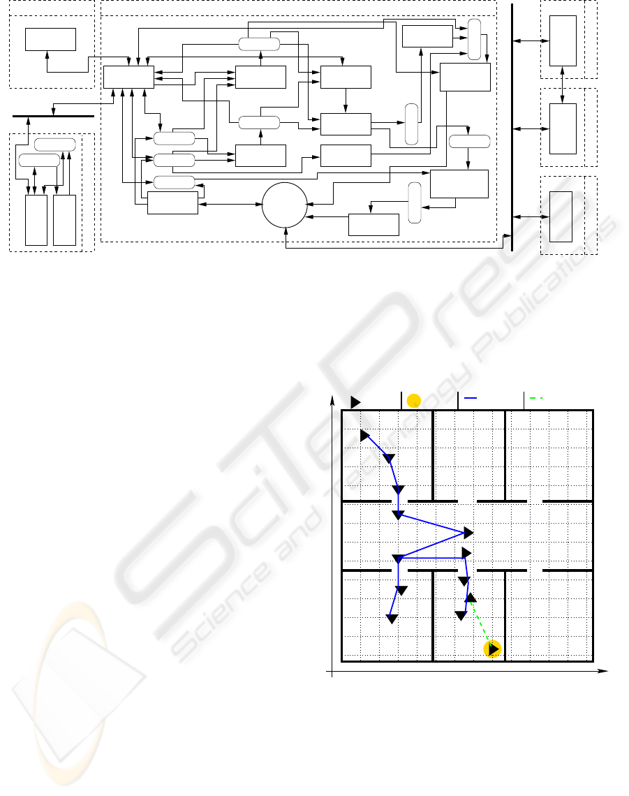
Blackboard
Blackboard
Blackboard
Blackboard
Blackboard
Blackboard
Blackboard
Blackboard
Blackboard
Blackboard
Blackboard
IEEE 802.11b
Ethernet
1A a 7A
Monitor
kapeck1
kapeck2
visionSis
Perception
Localizer
Cartographer
actionPl
pathPl
avoiderObs
headCon
refHeGen
posCon
refRoGen
bBoardServer
Interface
User
bBoardServer
CAN
Arbiter
1A a 7A
Controller
Supervisor
Sonar
Sonar Board
Encoder Velocity
Control
CAN Bus
Figure 3: Control Organization.
The refHeGen function in to possibles behaviors:
Standard behavior and Exploring behavior. In the
standard behavior, this module generates and exports
to a blackboard specific positions possible to reach
by the stereo head parts. In the exploring behavior
(started when actionPl triggers an action 2 and fin-
ished when the action 2 finishes), refHeGen starts to
read and export the positions generated by pathPl.
The visionSis processes the camera images to
find the desired mark. When the mark is discov-
ered, visionSis signals to actionPl. After this,
actionPl triggers an action 3. Together with the sig-
nal, visionSis exports the robot position to a black-
board.
5 EXPERIMENTAL RESULTS
The experiment developed in this work to demon-
strate the proposed architecture consists in a robot
that explores a priori known map to find a mark.
When the robot finds the mark, it goes to its
position. This experiment contains the follow-
ing software modules of proposed control organi-
zation: Perception, Localizer, Cartographer,
actionPl, pathPl, refRoGen, posCon, headCon,
refHeGen e visionSis.
In the Figure 4 we present the experimental re-
sults. In the moments T0, T3, T6 and T10 the
actionPl triggers an action 1. In the moments T1,
T4, T7 and T11 the actionPl triggers an action 2. In
the moments T2, T5, T8 and T12 the actionPl trig-
gers an action 4. In the moment T13 visionSis iden-
tifies the mark, signaling to actionPl. So, actionPl
triggers a action 3. At this moment, the robot dis-
cards the rest of path generated in moment T12 and
goes to the mark, using the coordinates provided by
visionSis. In the moment T14 the robot reaches the
mark and accomplishes the global task.
Y
X
T0
T1
0
T2
T3
T6
T7
T9
T10
T13
T14
T8
T12
T11
T4
T5
− Mark
− Original − Alternative
− Robot
Path Path
Figure 4: Experimental Results.
6 CONCLUSIONS
This work presented the main ideas of a hardware-
software architecture for an autonomous mobile
robot. In particular, we propose the using of black-
boards to implement the interection between software
modules. We also presented the CAN bus access
mode, using a logical representation of the real CAN
A DISTRIBUTED HARDWARE-SOFTWARE ARCHITECTURE FOR CONTROL AN AUTONOMOUS MOBILE
ROBOT
173

bus. The proposed architecture tries to manage not
only the organization software aspects, but also the
hardware organization and the interaction between
hardware and software modules. The concepts pre-
sented were applied to Kapeck. We pretend in next
works improve the software modules of the control or-
ganization and develop hardware and software mod-
ules to control the manipulators. In the current stage
of the work, we use a simple mechanism to coordi-
nate the access to the CAN bus. An evolution of the
work could be the utilization of a high-level protocol
on CAN.
REFERENCES
Adouane, L. and Le Fort-Piat, N. (2004). Hybrid behavioral
control architecture for the cooperation of minimal-
ist mobile robots. In Proceedings of ICRA’04, pages
3735–3740, New Orleans,USA.
Alami, R., Chantila, R., and Espiau, B. (1993). Designing
an inteligent control archtecture for autonomous mo-
bile robots. In Proceedings of ICAR’93, pages 435–
440, Tokyo, Japan.
Bosch, R. (1991). Bosch CAN specification. Technical re-
port, Bosch Gmbh.
Cormen, T. H., Leiserson, C. E., Stein, C., and Rivest, R. L.
(2002). Algoritmos: Teoria e Prtica. Campus, 1 edi-
tion.
Coronel, J. O., Benet, G., Sim, J. E., Prez, P., and Albero,
M. (2005). CAN-based control architecture using the
SCoCAN communication protocol. In Proceedings of
ETFA’05, Catania, Italy.
Hayes-Roth, B. (1985). A blackboard architecture for con-
trol. In Artificial Inteligence 26.
Heinen, F. J. (2002). Sistema de controle hbrido para robs
mveis autnomos. Master’s thesis, Centro de Cincias
Exatas e Tecnolgicas, UNISINOS, San Leopoldo, RS.
Kim, J.-O., Im, C.-J., Shin, H.-J., Yi, K. Y., and Lee, H. G.
(2003). A new task-based control architecture for per-
sonal robots. In Proceedings of IROS’03, pages 1481–
1486, Las Vegas, USA.
Ly, D. N., Asfour, T., and Dillmann, R. (2004). A mod-
ular and embedded control architecture for humanoid
robots. In Proceedings of IROS’04, pages 2775–2780,
Sendai, Japan.
Medeiros, A. A. D. (1998). A survey of control archi-
tectures for autonomous mobile robots. Journal of
Brazilian Computer Society.
Murphy, R. R. (2000). Introduction to AI Robotics. MIT
Press, Cambridge, Massachusetts 02142, 2 edition.
Roisenberg, M., Barreto, J. M., Silva, F. d. A., Vieira, R. C.,
and Coelho, D. K. (2004). Pyramidnet: A modu-
lar and hierarchical neural network architecture for
behavior-based robotics. In Proceedings of ISRA’04,
pages 32–37, Queretero, Mexico.
ICINCO 2008 - International Conference on Informatics in Control, Automation and Robotics
174
