
SYNTHESIS OF VELOCITY REFERENCE CAM FUNCTIONS FOR
SMOOTH OPERATION OF HIGH SPEED MECHANISMS
Robert M. C. Rayner and M. Necip Sahinkaya
Department of Mechanical Engineering, University of Bath, Claverton Down, Bath BA2 7AY, U.K.
Keywords:
Cam function, mechanisms, identification, control, simulation.
Abstract:
The purpose of the paper is to improve the dynamic performance of a mechanism used in a packaging machine
in order to run the system at higher speeds with lower vibration and noise levels. A method of synthesising
a velocity demand signal as a function of crank position (i.e. cam function) is demonstrated for a prototype
mechanism and drive system. The method aims to minimise the peak to peak actuation torque requirements
in order to minimise the vibration of the mechanism. First of all, experimental results are utilised to identify
the drive system parameters. A dynamic simulation package is used to model the nonlinear dynamics of the
mechanism. The model based synthesis of velocity reference cam functions is performed at increasing mech-
anism actuation speeds. The performance of the system using the proposed velocity demand cam function is
compared with the conventional constant speed reference case at different running speeds.
1 INTRODUCTION
The dynamic performance requirements of modern
machinery are constantly increasing in terms of op-
eration speed and motional accuracy. To remain
competitive, mechanisms need to run at ever higher
speeds, with greater reliability and be manufactured
at lower cost. To achieve this, machines use a com-
bination of electrical control systems, servo systems
and mechanisms to generate truly mechatronic solu-
tions. At the core of most packaging machines are
multi-linkage mechanisms, which interact with pack-
aging materials and products. These mechanisms
have highly nonlinear dynamic properties and intro-
duce vibrations at high operating speeds.
Much work has been documented on optimum
balancing of mechanisms in order to reduce the vi-
brations at high operating speeds, such as (Kochev,
2000; Lee and Cheng, 1984; Alici and Shirinzadeh,
2006) and others. This method involves the adding of
balancing masses to the mechanism, which increases
the weight and may not always be physically achiev-
able due to factors such as space restrictions. Al-
ternatively, a mechanism can be re-designed or re-
synthesised by considering kinematic and dynamic
cost functions (Conte et al., 1975; Kochev, 2000).
Due to the large number of parameters, conventional
optimisation techniques struggle. Many researchers
tried to formulate new optimisation techniques, such
as genetic algorithms (Connor et al., 1998; Cabr-
era et al., 2002; Laribi et al., 2004; Saxena, 2005),
differential evolution (Price and Storn, 2006), arti-
ficial immune searching (Liu and Xiao, 2005), geo-
metric centroid of precision positions technique (Shi-
akolas et al., 2005), and the time varying dimensions
method (Hansen, 2002).
It has been stated in (Yuan and Rastegar, 2004)
that vibrations experienced during high speed actua-
tion are caused by harmonic content in the output mo-
tion. It has also been argued in (Rastegar and Yuan,
2002) that the amount of harmonic content present in
the motion increases with the magnitude of the peak
to peak torque required to generate the motion. Re-
cently, an iterative method of synthesising a veloc-
ity command cam function has been introduced to re-
duce the peak to peak actuation torque (Sahinkaya
et al., 2007). This method relies on the develop-
ment of a computer model of the system. This model
is based on experimental results and a simulation of
the nonlinear dynamics of the mechanism. This pa-
per extends the aforementioned work by synthesis-
ing optimised cam functions (i.e. velocity profile as
a function of crank angle) to achieve higher output
speeds than that discussed previously, and that used
for the purpose of system identification.The use of
shaped cam functions has demonstrated significant
benefits in terms of reduced peak to peak torque re-
quirements.This is a software based command shap-
ing technique. No redesigning or re-synthesis of the
mechanism is necessary.
183
M. C. Rayner R. and Necip Sahinkaya M. (2008).
SYNTHESIS OF VELOCITY REFERENCE CAM FUNCTIONS FOR SMOOTH OPERATION OF HIGH SPEED MECHANISMS.
In Proceedings of the Fifth International Conference on Informatics in Control, Automation and Robotics - SPSMC, pages 183-187
DOI: 10.5220/0001501901830187
Copyright
c
SciTePress
2 SYSTEM DESCRIPTION AND
MODELLING
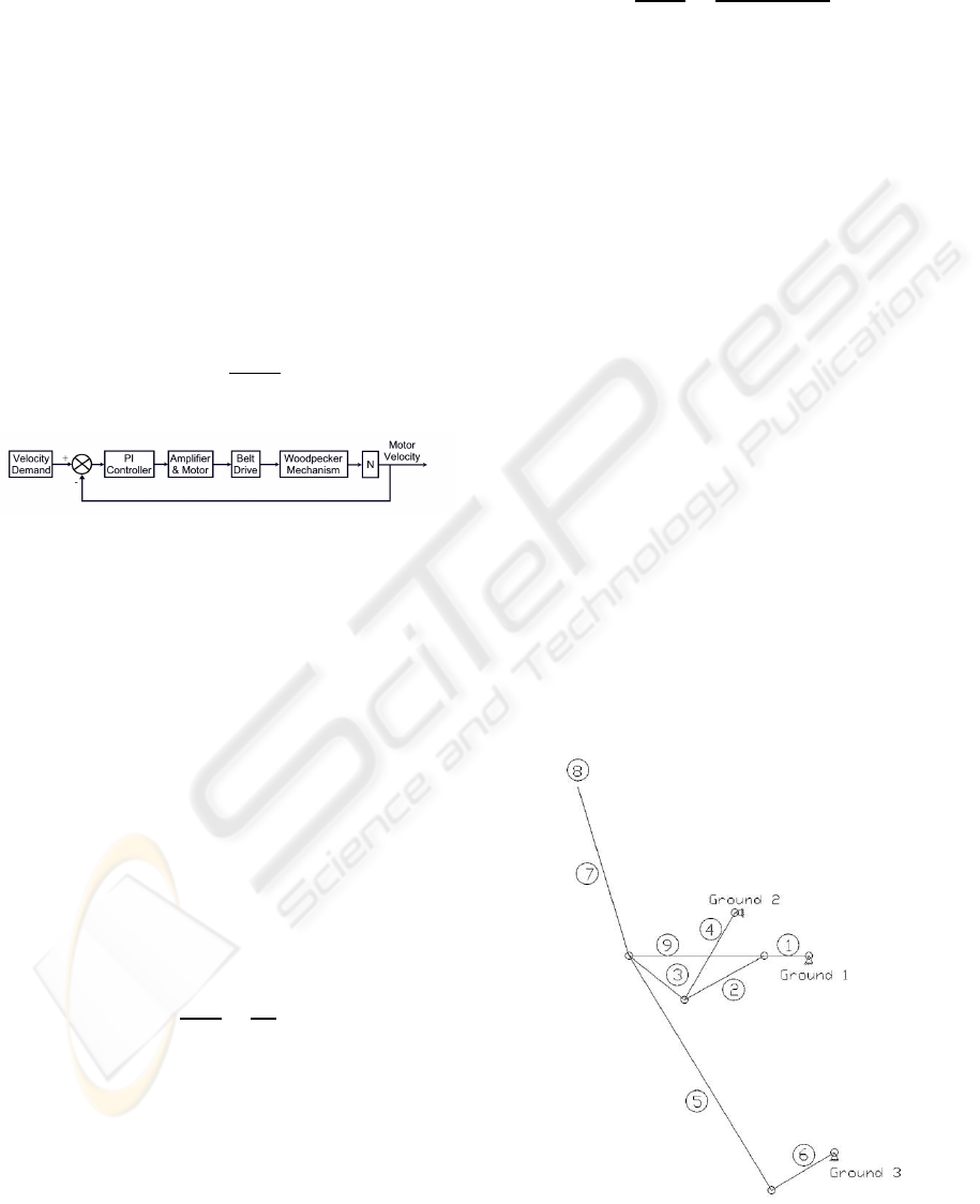
The block diagram of the prototype system consid-
ered in this study is shown in Figure 1. The mech-
anism is a 6-bar mechanism called the woodpecker
mechanism. The purpose of the mechanism is to push
thin products into packaging held in a neighbouring
hopper. The mechanism is driven by an Allen Bradley
MPL 540K-MJ22AA servo controlled with an Allen
Bradley Kinetix6000 drive unit via a belt drive with
a 3:1 gear ratio. The drive unit is fundamentally a PI
controller. The user can configure the drive unit and
monitor the system in real-time using RSLogix5000
control software. The servomotor and the drive sys-
tem is assumed to be a first order lag with a time con-
stant of τ and a gain K
m
.
G
m
=
K
m
1+ τs
(1)
Figure 1: Block diagram of the overall system.
Before modelling the nonlinear dynamics of the
woodpecker mechanism, experiments were carried
out to identify the drive system parameters. It was
possible to log the velocity demand, velocity out-
put, acceleration output, position output, and motor
torque. A step input velocity signal was used with
different values of K
P
and constant velocity demand.
The integral gain K
I
was set to zero during the iden-
tification process. To estimate the effective friction
coefficient acting on the motor shaft, the steady state
response over a single crank cycle was considered.
By using the approximate constant speed section of
the cycle, the friction coefficient b can be estimated
from the following transfer function between the mo-
tor torque (the output of ”Amplifier & Motor” block
in Fig. 1) and the motor velocity:
T
m,ss
˙
θ
m,ss
=
N
2
b
(2)
where T
m,ss
and
˙
θ
m,ss
are the average motor torque
and motor speed respectivelyalong the constant speed
section of the steady state cycle, and N is the gear
ratio, i.e. N = 3. This gave a representative fric-
tion coefficient of b = 0.255. In order to identify the
motor/amplifier gain K
m
and the effective rotor iner-
tia, tests were repeated by replacing the woodpecker
mechanism with a disk of known inertia. Thus the
steady state gain of the closed loop system can be
written as:
˙
θ
m,ss
˙
θ
m,ref
=
N
2
K
m
K
p
b+ N
2
K
m
K
p
(3)
By analysing the steady state system response, the
motor/amplifier gain was estimated as K
m
= 0.0883.
Transient motor torque and motor velocity data were
used to determine the effective inertia of motor shaft
and associated pulleys acting on the crank shaft. Thus
I
m
= 0.0071 kgm
2
. Observation of the transient mo-
tor torque and the error signal suggested that the time
constant τ can be taken as zero. This may be due to a
high-gain internal current feedback in the motor drive
circuit.
The dynamic model for the woodpecker mecha-
nism was built in Simulink by using
Dysim
(Haz-
lerigg and Sahinkaya, 1984; Sahinkaya, 2004) sim-
ulation package. The mechanism consists of 6 links
as shown in Figure 2. The physical data is given in
Table 1. A CAD model of the mechanism was used
to obtain these mass and inertia values and the po-
sition of the centre of gravity of each link and local
coordinates of the connection points. The model was
then tested using various demand speed and controller
parameter combinations. For example, Fig. 3 shows
the experimental and simulation results for a constant
speed reference of 300 rpm with K
P
= 20 and K
I
= 0.
The results showed an excellent match between
the experimental and simulated responses for all the
tests conducted with the prototype system. The high
Figure 2: A schematic view of the woodpecker mechanism.
ICINCO 2008 - International Conference on Informatics in Control, Automation and Robotics
184
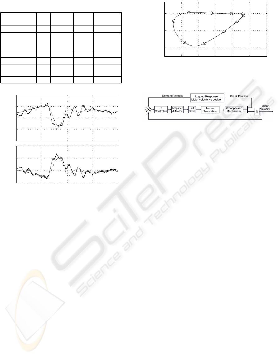
Table 1: Data for the Woodpecker mechanism.
Name No Length Mass Inertia
(mm) (kg) (N·mm
2
)
Crank 1 62 0.927 901
Connector 2 127 0.310 1420
3 103
9 188.3
Upper pivot 4 144 0.414 1310
End-effector 8 0.174 380
Spine 5 348.86 0.482 10550
7 245.19
Lower pivot 6 102 0.123 290
180
200
220
240
260
Motor Velocity (rpm)
0 90 180 270 360
0.4
0.6
0.8
1
Crank Position (degrees)
Motor Torque (Nm)
Figure 3: Simulated (dashed) and experimental (solid)
steady state responses over one crank cycle.
frequency oscillations (of approximately at 15 Hz.)
in the measured response were due to the belt dynam-
ics, which were not included in the analysis. Partic-
ularly encouraging was the reproduction in the simu-
lated results of the velocity trough and corresponding
torque peak resulting from the nonlinear nature of the
mechanism dynamics. The orbit of the end effector is
shown in Figure 4. Normalised crank positions (unity
normalised crank position corresponds to 360
o
crank
angle) are shown on the orbit. The critical portion
of the path is between normalised crank positions of
0.6 and 1.0, where the end-effector interacts with the
product and product feeding mechanism.
3 OPTIMUM CAM PROFILE
The experimental results highlighted a potential prob-
lem when running the system at higher speeds. Of
particular concern was the torque spike and trough
on the return part of the end-effector orbit between
crank positions 90 and 180 degrees. It has been
shown elsewhere (Yuan and Rastegar, 2004) that har-
monic content in the output motion induces vibra-
−0.25 −0.2 −0.15 −0.1 −0.05 0
0.15
0.2
0.25
x−position (m)
y−position (m)
0.0
0.1
0.2
0.3
0.4
0.5
0.6
0.7
0.8
0.9
Figure 4: Orbit of the end-effector.
Figure 5: The process of optimising a velocity cam func-
tion.
tions and that the amount of harmonic content in-
creases with the peak-to-peak magnitude of the ac-
tuation torque (Rastegar and Yuan, 2002). Therefore,
the focus of the paper is to reduce the peak-to-peak
drive torque through shaping the speed reference sig-
nal as a function of crank angle. The machanisms
will not be re-synthesise nor rebuilt. The method sug-
gested in (Sahinkaya et al., 2007) utilises the model of
the drive system estimated from experimental results.
The procedure can be summarised as follows:
(a) Run the simulation of the overallsystem for a con-
stant speed reference signal, and determine a nar-
row torque band from the steady state torque sig-
nal covering the approximate constant torque re-
gion.
(b) Run the simulation again with the same constant
speed reference signal, but with saturation limits
imposed on the drive torque. These limits are de-
termined in (a). Then record the steady state out-
put speed response over a single cycle of crank
logged against crank position.
(c) Use the periodic output speed recorded in (b)
as a velocity cam function and run the simula-
tion without saturation limits to assess the perfor-
mance of the system with this velocity cam func-
tion.
This process is shown in Figure 5 as a block diagram.
The above process is applied to the model of the
prototype system to assess the benefit of the veloc-
ity cam function when the average running speed of
the mechanism is increased from to 100 rpm to 600
rpm. Due to the 3:1 gear ratio, this corresponds to
SYNTHESIS OF VELOCITY REFERENCE CAM FUNCTIONS FOR SMOOTH OPERATION OF HIGH SPEED
MECHANISMS
185
0 90 180 270 360
0.7
0.8
0.9
1
1.1
1.2
Crank position (degrees)
Normalised Motor Reference Velocity
Constant demand
100rpm cam function
300rpm cam function
450rpm cam function
600rpm cam function
Figure 6: Velocity reference cam functions at different av-
erage crank speeds.
motor speeds from 300 rpm to 1800 rpm. The con-
troller parameters are set to K
P
= 20 and K
I
= 400.
Figure 6 shows the synthesised cam functions at 300,
900, 1350, and 1800 rpm of the motor speed. For ease
of comparison, the velocity reference signals are nor-
malised by their corresponding constant speed values.
Note that in each case the achieved average cyclic ve-
locity of the mechanism corresponded closely to the
demand velocity.
Figure 7 shows the corresponding steady state
crank velocity output over a single crank cycle. Es-
pecially at higher speeds, the change in system re-
sponse is minimal compared with the constant speed
reference signal cases. Despite small variations in the
output velocity profile, the use of the optimised cam
function has significant benefits, greatly reducing the
peak to peak drive torque requirements as shown in
Figure 8. The benefit of the optimised cam function
can be better appreciated from Figure 9, where the
reduction in peak to peak torque variations are 99%,
80%, 78%, and 78% for the crank speeds of 100, 300,
450, and 600 rpm respectively.
Although it is not included in the optimisation pro-
cess, the optimised velocity cam functions also reduce
the maximum drive motor power requirements com-
pared with the constant velocity signal case as shown
in Figure 10.
4 CONCLUSIONS
This paper demonstrates the benefit of using a veloc-
ity cam function as a velocity demand signal to reduce
the peak to peak actuation torque of a servo driven
mechanism. The drivesystem parameters were identi-
fied using experimental data, and then combined with
0 90 180 270 360
0.6
0.8
1
1.2
100 rpm
Crank Velocity
0 90 180 270 360
0.6
0.8
1
1.2
300 rpm
0 90 180 270 360
0.6
0.8
1
1.2
450 rpm
Crank position (degrees)
Crank Velocity
0 90 180 270 360
0.6
0.8
1
1.2
600 rpm
Crank position (degrees)
Figure 7: Normalised crank velocity output at different
crank speeds (solid: constant reference, dashed: shaped ref-
erence).
0 90 180 270 360
0.4
0.6
0.8
1
1.2
1.4
100 rpm
Motor Torque (Nm)
0 90 180 270 360
0
1
2
3
4
5
300 rpm
0 90 180 270 360
0
2
4
6
8
450 rpm
Crank position (degrees)
Motor Torque (Nm)
0 90 180 270 360
0
2
4
6
8
10
600 rpm
Crank position (degrees)
Figure 8: Drive torque at different crank speeds (solid: con-
stant reference, dashed: shaped reference).
a nonlinear dynamic model of the mechanism. The
identification was carried out at a crank speed of 100
rpm. The accuracy of the computer model has been
verified using experimental results. Utilising the com-
puter model, a three-stage synthesis of the velocity
demand cam functions has been performed at much
higher operational speeds up to 600 rpm. The results
show that a reduction in peak to peak actuation torque
of as much as 80% can be achieved at high speeds
without significantly affecting the speed response of
the system. Although no effort has been made to min-
imise the energy consumption, sizable reductions in
the maximum motor power requirements have also
been predicted.
ICINCO 2008 - International Conference on Informatics in Control, Automation and Robotics
186
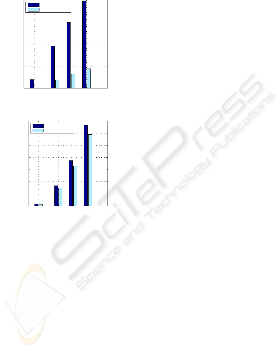
100 300 450 600
0
1
2
3
4
5
6
7
8
Crank speed (rpm)
Peak to peak variation (Nm)
constant demand
shaped demand
Figure 9: Peak to peak drive torque variations at different
crank speeds.
100 300 450 600
0
200
400
600
800
1000
1200
1400
Crank speed (rpm)
Maximum power requirement (W)
constant demand
shaped demand
Figure 10: Maximum drive power requirements at different
crank speeds.
ACKNOWLEDGEMENTS
The authors acknowledge the support of the Engi-
neering and Physical Sciences Research Council (EP-
SRC) of the U.K. and the industrial partner ITCM,
Coventry, UK through the EPSRC Industrial Case
Studentship Award Voucher No: 05002188.
REFERENCES
Alici, G. and Shirinzadeh, B. (2006). Optimum dynamic
balancing of planar parallel manipulators based on
sensitivity analysis. Mechanism and Machine Theory,
41(12):1520–1532.
Cabrera, J. A., Simon, A., and Prado, M. (2002). Opti-
mal synthesis of mechanisms with genetic algorithms.
Mechanism and Machine Theory, 37(10):1165–1177.
Connor, A. M., Douglas, S. S., and Gilmartin, M. J. (1998).
The use of harmonic information in the optimal syn-
thesis of mechanisms. Journal of Engineering Design,
9(3):239–249.
Conte, F. L., George, G. R., Mayne, R. W., and Sadler,
J. P. (1975). Optimum mechanism design combining
kinematic and dynamic-force considerations. Journal
of Engineering for Industry-Transactions of the Asme,
97(2):662–670.
Hansen, J. M. (2002). Synthesis of mechanisms using
time-varying dimensions. Multibody System Dynam-
ics, 7(1):127–144.
Hazlerigg, A. D. G. and Sahinkaya, M. N. (1984). Com-
puter aided design of non-linear systems. In ACC 84
Conference, pages 1498–1503.
Kochev, I. S. (2000). General theory of complete shaking
moment balancing of planar linkages: a critical re-
view. Mechanism and Machine Theory, 35(11):1501–
1514.
Laribi, M. A., Mlika, A., Romdhane, L., and Zeghloul, S.
(2004). A combined genetic algorithm-fuzzy logic
method (ga-fl) in mechanisms synthesis. Mechanism
and Machine Theory, 39(7):717–735.
Lee, T. W. and Cheng, C. (1984). Optimum balancing
of combined shaking force, shaking moment, and
torque fluctuations in high-speed linkages. Jour-
nal of Mechanisms Transmissions and Automation in
Design-Transactions of the Asme, 106(2):242–251.
Liu, Y. and Xiao, R. B. (2005). Optimal synthesis of mech-
anisms for path generation using refined numerical
representation based model and ais based searching
method. Journal of Mechanical Design, 127(4):688–
691.
Price, K. and Storn, R. (2006). Differential evolution (DE),
http://www.icsi.berkeley.edu/ storn/code.html. Elec-
tronic Citation.
Rastegar, T. and Yuan, L. (2002). A systematic method for
kinematics synthesis of high-speed mechanisms with
optimally integrated smart materials. Journal of Me-
chanical Design, 124(1):14–20.
Sahinkaya, M. N. (2004). Inverse dynamic analysis of mul-
tiphysics systems. Proceedings of the Institution of
Mechanical Engineers Part I- Journal of Systems and
Control Engineering, 218(I1):13–26.
Sahinkaya, M. N., Rayner, R. M. C., Vernon, G., Shirley,
G., and Aggarwal, R. K. (2007). Synthesis of demand
signals for high speed operation of a packaging mech-
anism. In ASME International Design Engineering
Technical Conferences & Computers and Information
in Engineering Conference (IDETC).
Saxena, A. (2005). Synthesis of compliant mechanisms for
path generation using genetic algorithm. Journal of
Mechanical Design, 127(4):745–752.
Shiakolas, P. S., Koladiya, D., and Kebrle, J. (2005). On the
optimum synthesis of six-bar linkages using differen-
tial evolution and the geometric centroid of precision
positions technique. Mechanism and Machine Theory,
40(3):319–335.
Yuan, L. F. and Rastegar, J. S. (2004). Kinematics synthe-
sis of linkage mechanisms with cam integrated joints
for controlled harmonic content of the output motion.
Journal of Mechanical Design, 126(1):135–142.
SYNTHESIS OF VELOCITY REFERENCE CAM FUNCTIONS FOR SMOOTH OPERATION OF HIGH SPEED
MECHANISMS
187
