
OBJECT EXPLORATION WITH A HUMANOID ROBOT
Using Tactile and Kinesthetic Feedback
Nicolas Gorges, Stefan Gaa and Heinz W
¨
orn
Institute for Process Control and Robotics, University of Karlsruhe, Engler-Bunte-Ring 8, Karlsruhe, Germany
Keywords:
Tactile Sensing, Object Exploration, Robot Control, and Humanoid Robot.
Abstract:
This work deals with the reactive and autonomous exploration of objects with a humanoid robot using only
tactile and kinesthetic sensor feedback. To coordinate the flow of the exploration, a novel hierarchical explo-
ration system is introduced. The lowest level extracts contacts points and elementary features based on the
direct contact with the object. It furthermore provides elementary movement primitives. The intermediate
level consists of different controlling behaviors to generate exploration movements according to the sensor
feedback. This level enables the robot to explore an object pointwisely or continously. The highest level eval-
uates the process of the exploration and determinates the reactive behavior of the underlying components. The
evaluation scenario comprises the exploration of edges, which are arbitrarily located in space. The evaluation
platform consists of a robot arm, a force-torque sensor, and a tactile sensor matrix. The proposed approach is
evaluated and the different reactive behaviors as well as the used sensor modalities are compared.
1 INTRODUCTION
Service robots build a new block of research area.
Their range of application highly differ from conven-
tional industrial robot, as they are rather deployed in
a domestic environment and are usually not intended
for repetitive tasks with need for high precision or
high forces. Typical tasks for a humanoid robot are
all kinds of fetch and carry or manipulation tasks with
a broad variety of objects. Not all of these object
can be assumed to be known appriori. The robot
might encounter unknown or partially unknown ob-
jects. Therefore, the robot has to use its sensors, like
visual or haptic sensors, to explore an unknown ob-
ject. The visual exploration is adequate to determine
the location and the rough shape of an object but it
is limited due to the ambiguity of visual data and the
need for textured objects as well as good light condi-
tions.
The haptic exploration describes the active palpa-
tion of objects. The relevant parts of the haptic explo-
ration are the tactile perception (surface sensibility)
and the kinesthetic perception (depth sensibility). A
haptic exploration procedure of an object requires the
direct interaction of the robot with the object. On the
one hand, this delivers accurate 3D information about
the object but, on the other hand, requires a reactive
control strategy to bring the sensors into the right po-
sition.
Previous work in (Klatzky et al., 1987) (Leder-
man and Klatzky, 1987) identified the following ex-
ploration procedures from observing human explo-
ration behavior: lateral motion, pressure, enclosure,
and contour following.
These procedures allows to determine the texture,
hardness, shape and size of an object by haptic ex-
ploration. The exploration procedure of this work pri-
marily focuses on the procedure of contour following.
Here, the tactile perception is represented by a tac-
tile sensor matrix whereas the kinesthetic perception
is given by a force-torque sensor. Robotic exploration
procedures so far include approaches with grippers
(Schmidt et al., 2006) and with tactile sensor matri-
ces (Chen et al., 1995), (Heidemann and Schoepfer,
2004).
A major problem for such exploration tasks is the
detection of a contact with the object to be explored.
The limitation is usually given by the sensibility and
the spatial resolution of the sensor. Therefore, many
approaches using tactile sensors assume that the sen-
sor is already located directly at the region of interest.
In order to avoid this restriction, this work intro-
duces a novel approach by coupling the information
of a force-torque sensor in the wrist and a tactile sen-
274
Gorges N., Gaa S. and Wörn H. (2008).
OBJECT EXPLORATION WITH A HUMANOID ROBOT - Using Tactile and Kinesthetic Feedback.
In Proceedings of the Fifth International Conference on Informatics in Control, Automation and Robotics - RA, pages 274-281
DOI: 10.5220/0001502702740281
Copyright
c
SciTePress
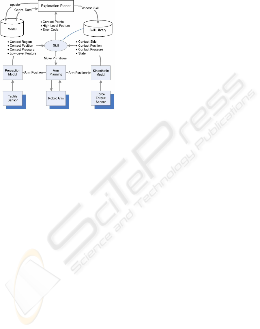
Figure 1: A system overview.
sor matrix representing the pose of an opened hand.
This enables the robot on the one hand to detect di-
rect contacts using the tactile sensor matrix, which
are very accurate but less sensitive, and on the other
hand to detect indirect contacts using the force-torque
sensor and a model of the hand, which make it less
accurate but very sensitive.
The remainder of this paper is structured as fol-
lows: After this introduction, the system overview of
this approach is discussed in section 2 followed by the
perception level in section 3. Our results are presented
in section 4 before conclusions are given in section 5.
2 SYSTEM OVERVIEW
In order to consecutively determine the shape of an
object, a concept consisiting of three components is
introduced, as shown in figure 1. Here, the highest
level is represented by the exploration planer. A re-
active control layer complies with the skill library,
from which consecutively a skill is chosen and ex-
ecuted. The haptic layer builds the lowest block of
the framework and is realized by three components:
tactile perception, arm planning and kinesthetic per-
ception. The planning layer and the reactive control
layer are explained in the following. The haptic layer
is presented separately in section 3.
2.1 Exploration Planner
The exploration planner makes decisions based on the
geometric shape of an object which can be determined
by a successive palpation sequence. Based on the es-
timate of the object’s shape, it determines the align-
ment of the robot towards the object. The planner ex-
ecutes a sequence of skills whereas the skills provides
the planner with contact features during their execu-
tion. The planner evaluates the alignment towards the
object and chooses a different skill if neccessary.
2.2 Exploration Skills
In this work, the exploration skills represent strategies
to explore structures of an object. They are elemen-
tary operations for the exploration procedure and are
executed by the superior global exploration compo-
nent. A sequence of simple exploration skills leads to
a complex exploration behavior.
Their key tasks are the coordination of the arm
control and the creation of a defined exploration be-
haviors according to the preprocessed data. A skill
has to fulfill two objectives. First of all, it has to bring
the robot arm into the right position which is realized
by a sequence of states. Secondly, it has to provide
the planning level with an amount of contact points.
To fulfill these tasks, a skill can access the underly-
ing haptic components. The planning level supervises
the execution of a skill and interprets the features pro-
vided by a skill in a global context.
A single skill is represented by a state machine
which determines the flow of action. Such a skill is
able e.g. to follow a structure or to rotate around a
structure according to its task definition. The most
states imply a coordination of sensor data and move-
ments but also include instructions from the upper
level. In general, the skills can be separated into two
groups:
• Skills with discrete movements
• Skills with continuous movements
These two types of skills are explained in more detail
in the following.
2.2.1 Skills with Discrete Movements
Skills with discrete movements are characterized by a
palpation sequence as the skill departs from the object
after establishing a contact before moving the arm to
next position of interest. This is achieved by move-
ment and control primitives which are the building
blocks of the total movement. Movement primitives
enable the robot to move with respect to a local or a
global coordinate system. Control primitives also em-
bed sensor data during a movement, e.g. to buildup a
certain amount of pressure. Here, the communication
between a skill and the planer is destinctive. The ben-
efit is that structures can be explored systematically
whereas the drawback is that they can only perform
an alignment according to point contacts. They need
OBJECT EXPLORATION WITH A HUMANOID ROBOT - Using Tactile and Kinesthetic Feedback
275
robot
arm
Force
torque
sensor
+
φτ
act
−
φτ
des
+
−
tactile
sensor
θ
act
θ
des
θ
err
position
control
φτ
Err
<φτ
Tol
tactile
perception
kinesthatic
perception
tactile
control
π
des
kinesthatic
control
π
des
+
1/2
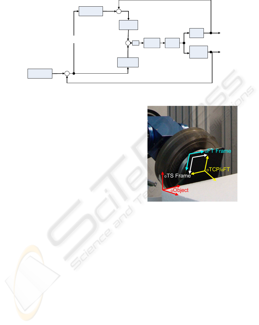
Figure 2: A control loop for skills with continous movements
at least two contact points to perform an alignment
and also depend on the measuring accuracy of these
contact points.
The process of tracking an edge, for example, can
be summarized as a sequence of the control and move-
ment primitives ¨move up¨, ¨move to the side¨, ¨move
down”, and ¨detect contact¨. A sequence of this skill
results into a simple but effective exploration proce-
dure.
2.2.2 Skills with Continuous Movements
The exploration behavior of skills with continuous
movements is given by a complex control loop, e.g.
zero-force control or a tactile control. At first, these
kind of skills establish a contact with the object sur-
face. Then, using a superior control loop, they try to
keep a steady contact towards the surface. Figure 2
shows the basic structure of such a superior control
loop. It shows a cascaded system with the force con-
trol preceding the tactile control. It is characterized
by a coarse control based on the measured forces and
torques of the force-torque-sensor and by a fine con-
trol based on the measured pressure profile.
The idea is to use the force-torque sensor to keep
the applied pressure φτ
des
stable. On the one hand,
the applied pressure should not exceed a given limit
as it could damage the robot or the object. On the
other hand, the pressure should not be too little as the
tactile sensor matrix would not be able to measure an
adequate pressure profile anymore and the sensor pad
could even loose contact to the object surface. The
tactile control loop is activated as soon as the applied
pressure is within an acceptable interval, expressed by
φτ
err
< φτ
tol
. The tactile control loop is defined by the
deviation θ
err
of the center of the tactile image from
center of the sensor pad. The position corrections τ
des
are given to the position control of the robot. This
Figure 3: Setup of the evaluation platform and the involved
coordinate systems.
enables the robot arm to align to the object and follow
its surface.
3 PERCEPTION
The perception level is part of the lowest level. It pre-
processes the data provided by the tactile sensor and
the force-torque sensor. The perception in this work
is therefore split into the tactile and kinesthetic per-
ception. In the course of the paper, the tactile sen-
sor matrix refers to the tactile perception whereas the
force-torque sensor represents the kinesthetic percep-
tion. Figure 3 show the setup of the evaluation plat-
form. It shows the tactile sensor and the force-torque
sensor mounted to the robot arm. Furthermore, it il-
lustrates the different coordinate systems which are
involved in the perception layer.
The tactile sensor identifies very accurately the
position of contacts caused by a direct touch. But
ICINCO 2008 - International Conference on Informatics in Control, Automation and Robotics
276

a small change in the orientation of the tactile sen-
sor matrix causes a significant chance in the resulting
tactile image. Imagine an imprint of an edge on the
tactile sensor, a small twist along the perpendicular
image axis of the edge, makes the edge disappear un-
til only a single point contact is determined. After a
certain angle between the tactile sensor and the sur-
face, no contacts can be detected as the sensor only
turns normal forces into a pressure profile. This angle
is called the critical angle.
The force-moment sensor, on the other hand, is
not able to determine contacts in the inner regions of
the sensor pad’s surface. It can only detect the direc-
tion from the center point of the sensor to the border
of the surface.
There is a simple decision rule for the determina-
tion of a contact, combining the tactile and the force-
moment-sensor:
1. If the tactile sensor detects a contact, the contact
must be inside the surface of the sensor pad. This
is called a TS-contact and is the desired type of
contact.
2. If the tactile sensor does not detect a contact but
the kinesthetic perception does, the contact must
be at the border of the sensor pad. We call this a
FTS-contact.
It is obvious that the tactile sensor can only take
a pressure profile if the robot apply enough force to-
wards the direction of the object surface. Therefore,
the more sensitive force-torque sensor is used to reg-
ulate the pressure applied to the object.
3.1 Tactile Perception
3.1.1 Working Principle
As already investigated and published by Weiss et
al. (Weiss and Woern, 2005), the working principle
of the tactile sensors depends on an interface effect
between the metal electrodes and the structured con-
ductive polymer covering the sensing electrodes. The
resistance between the common electrode and a sen-
sor cell electrode is a function of the applied load and
time. This technique leads to very accurate pictures of
the applied pressure profile and minimizes crosstalk
between the sensor cells as well.
As each sensor cell represents a measured voltage,
the voltage image has to be transferred to a pressure
image. This characteristic curve of the tactile sensor
can be obtained by calibration.
3.1.2 Tactile Feature Extraction
Identifying the characteristic features of an image us-
ing moments is a well known paradigm in image pro-
cessing. The data of the tactile sensor matrix corre-
sponds to a two-dimensional planar image. We an-
alyze this image using moments up to the 2
nd
order
(Hu, 1962). The two-dimensional (p +q)
th
order mo-
ment m
p,q
of an image is defined as the following dou-
ble sum over all image pixels (x,y) and their values
f (x,y):
m
p,q
=
∑
x
∑
y
x
p
y
p
f (x,y) p,q ≥ 0 . (1)
The moment m
0,0
constitutes the resulting force ex-
erted on the sensor. The center of gravity x
c
=
(x
c
,y
c
)
T
of this force can be computed to
x
c
=
m
1,0
m
0,0
(2)
y
c
=
m
0,1
m
0,0
. (3)
Using the center of gravity, we can verify that the ob-
ject surface is aligned to the center of the sensor pad.
It also allows to calculate the higher order moments
with respect to the center of gravity, the so-called cen-
tral moments µ
p,q
:
µ
p,q
=
∑
x
∑
y
(x − x
c
)
p
(y − y
c
)
q
f (x,y) p,q ≥ 0 . (4)
The 2
nd
order central moments
µ
2,0
=
∑
x
∑
y
(x − x
c
)
2
f (x,y) (5)
µ
0,2
=
∑
x
∑
y
(y − y
c
)
2
f (x,y) (6)
µ
1,1
=
∑
x
∑
y
(x − x
c
)(y − y
c
) f (x,y) (7)
approximate the image by an ellipse and represent its
principal axes. The eccentricity of a contact is de-
scribed by the relation of the eigenvalues λ
1
and λ
2
. If
both eigenvalues have a similar value, then the contact
area has a round shape and the eccentricity is close to
zero. For these contacts it is not possible to calculate
the orientation.
Touching an edge results in an oblong ellipse with
an eccentricity ε close to 1 when using
ε =
(µ
2,0
− µ
0,2
)
2
+ 4µ
2
1,1
(µ
2,0
+ µ
0,2
)
2
ε ∈ [0, 1] . (8)
A corner point results to an eccentricity close to zero.
To control the orientation of the sensor pad with re-
spect to the object surface, we are interested in the
OBJECT EXPLORATION WITH A HUMANOID ROBOT - Using Tactile and Kinesthetic Feedback
277
Figure 4: The angle θ between the principal axes of the
tactile image and the sensor coordinate system.
Figure 5: The 9 regions of
the sensor pad.
Figure 6: Evaluation of a
contact point.
angle θ between the principal axes and the sensor co-
ordinate system (cf. Fig. 4) which can be readily com-
puted by
θ =
1
2
arctan
2µ
1,1
µ
2,0
− µ
0,2
. (9)
When tracking an edge, the desired angle θ is zero
and can thus be directly used as the system deviation
input to the controller to control one orientation DOF.
The angle theta will be also referred to as the quality
measure q
1
in the following.
To evaluate a contact point regarding to the orien-
tation along the y-axis, we compute a quality measure
from the distance |y
c
−y
p
| of the contact point (x
c
,y
c
)
to the center of the sensor pad called (x
p
,y
p
). As the
correlation between this distance and the angle is not
linear, we weight the distance by a circular function.
This circular function f with the radius r is given by
f
r
(x) =
p
r
2
− x
2
(10)
This results into the function
q
2
=
q
y
2
p
− |y
c
− y
p
|
2
(11)
Figure 6 illustrates the computation of this quality
measure which is used for the alignment of the sen-
sor pad towards the object surface.
Furthermore, we devide the pad into 9 regions: 4
corner regions, 4 border regions and one interior re-
gion, as shown in figure 5. Each region is checked,
if it accommodates a contact or not. This computa-
tion results into a 9-dimensional binary feature vector
which can be used for a simple classification like the
determination of corner contacts or contact side, de-
pending on the present context.
3.2 Kinesthetic Perception
The force-torque sensor that we use is an FTC 50-40
from SCHUNK. It has 6DOFs, with a range of 150N
for the forces, 4Nm for the torques Mx and My, and
8Nm for Mz. The accuracy is 5%. The data is sam-
pled every 1ms and transmitted via CAN bus with a
baudrate of 500kbit/s.
Since the data is quite noisy, the preproccesing of
the sensor data includes a median filter with window
size 7 to remove outliers. Since the tactile sensor pad
is mounted on the top of the sensor, we must deduct
its weight from the sensor values.
The compensation of the torques and forces is
only possible in the global robot coordinate system
and not in the local system. Local compensated forces
are computed via back-transformation of global com-
pensated forces into local coordinates. The required
transformation steps are f
l
→ f
g
→ f
g,c
→ f
l,c
, where
l and g mark local coordinated and global respec-
tively. The marker c describes compensated values.
It is possible to determine contacts without
the tactile sensor by relating the measured torques
(m
x
,m
y
,m
z
) with a model of the used sensorpad. The
sensorpad can be described as a simple rectangle with
the length (l
x
,l
y
). The angle α from the center of
the pad to the contact point can be calculated by
atan(m
x
/m
y
). The angle furthermore describes, if a
contact is safe or not. A corner contact is declared
as unsafe, as is it not accurate enough to identify the
correct contact side.
4 RESULTS
At first, the measuring accuracy of the contact points
is investigated using the tactile and the force-torque
sensor. Then, the implementation of a skill with dis-
crete movements for edge tracking is shown. This
skill is used to evaluate the exploration with each sen-
sor in a stand-alone application and with a combina-
tion of both sensors. Finally, a skill with continuous
movements is shown and evaluated.
ICINCO 2008 - International Conference on Informatics in Control, Automation and Robotics
278
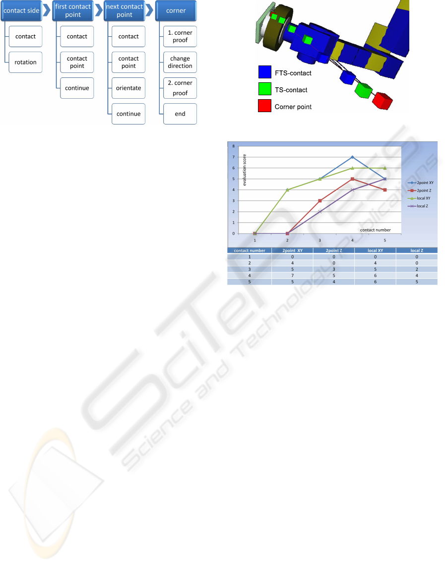
Figure 7: Implementation of a discrete skill.
4.1 Measuring Accuracy
To obtain the measuring accuracy of the tactile and the
force-torque sensor, reference and measured points
are generated consecutively along a line with a dis-
placement of 1.0 cm in relation to the center of the
tactile sensor pad. The measured contact points are
determined by the interpolation of the contact area in
the resulting tactile image. This simple experiment
has shown that the used tactile sensor matrix with a
cell distance of 0.6 cm has a mean square error of
0.2 cm. Furthermore, the accuracy is not correlated
to the location of the contact point. A similar ex-
periment has been done for testing the force-torque
sensor. Here, the reference points were taken only at
the boundary of the sensor pad. The measured mean
square error is 0.6 cm.
The tactile sensor is superior to the force-torque
sensor regarding the measuring accuracy. The tacile
has one significant disadvantage - it exist a critical
angle which restricts the operational area. Applying
the maximum force of 8N towards a planar surface,
the critical angle is 18 degrees. If the sensor pad is
aligned with a larger angle towards the object, a con-
tact cannot be detected anymore.
4.2 Discrete Skill for Edge Tracking
4.2.1 Implementation
The objective is a skill which pointwisely tracks an
edge. Figure 7 shows a coarse view of the implemen-
tation of such a skill consisting of 4 main states and
several sub-states. The skill tracks the contour of an
edge and changes the direction of exploration as soon
as the first corner has been detected. The first state
involves the determination of the first contact and the
contact side. Therefore, the robot arm moves into a
specified direction until it detects a contact and de-
parts again. According to this first contact, the orien-
tation of the sensor pad is aligned so that the long side
Figure 8: Visualisation of the exploration procedure.
Figure 9: Evaluation using only force-torque sensor.
of the pad is used for tracking the edge. After this ini-
tial alignment, the first contact point is collected and
the arm departs again. The first two steps are only
executed once.
The third step is executed consecutively until a
corner point and hence the end of the edge is detected.
This step collects the next contact point, departs from
the object, evaluates the current spatial alignment, and
executes a correction of the alignment. If a corner is
detected by the tactile perception, the fourth phase is
triggered which involves the decision to change the
direction of the exploration, if the first corner has been
detected, or to stop the exploration if the final cor-
ner has been found. Figure 8 visualizes the outcome
of such an exploration procedure: a set of points and
lines.
4.2.2 Force-torque Sensor vs. Tactile Sensor
To compare both sensors, the implemented skill has
been executed once only with the force-torque sen-
sor and another time only with the tactile sensor ma-
trix. In order to make the skill be executable for both
sensors in a stand-alone application, several require-
ments must be considered. At first, the sensor pad
was aligned with an angle of 10 degrees towards the
object. Secondly, the exploration procedure only in-
OBJECT EXPLORATION WITH A HUMANOID ROBOT - Using Tactile and Kinesthetic Feedback
279
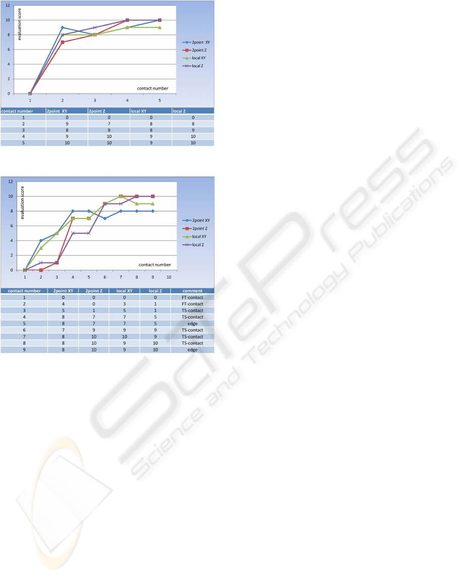
Figure 10: Evaluation using only tactile sensor.
Figure 11: Evaluation using force-torque sensor and tactile
sensor.
volves tracking the edge in one direction up to the first
corner, as the force-torque is not able to detect the
corner of an edge. After the second contact point, the
alignment towards the edge is evaluated.
For tracking an edge two alignments are needed.
At first, the imprint of the edge must be parallel to
a specified boundary of the sensor pad. Secondly,
the center of gravity of the contact point must be in
the center of the sensor pad. For these two align-
ments, two quality measures were introduced in sec-
tion 3. For the sake of convenience, these two qual-
ity measures will be scaled to a score from zero to
ten whereas ten indicates a good score. The score
XY refers to the difference between the center of the
contact point and the center of the sensor pad, as de-
scribed in equation 11. The second score Z refers to
the deviation of the angle of the edge, as stated in
equation 9. The prefix 2-Point indicates that only the
last two contact points are used for an estimate of the
edge whereas the prefix Local points out that all ex-
tracted point so far are taken into account.
Both experiments haven been repeated several
times. Representative results of both experiments are
shown in figures 9 and 10. The diagrams plot four
curves which result from two quality measures for the
current alignment, labelled 2-Point-XY and 2-Point-Z
and two quality measures for the alignment over sev-
eral exploration steps, labelled Local-XY and Local-Z.
As to be expected, the tactile sensor scores well
with an average score of about 9 points for both qual-
ity measures. The results of the force-torque sensor is
worse with an average score of 5 points. Furthermore,
the tactile edge tracking converges faster towards the
optimum of the quality measures. Both sensors en-
able the robot to explore an edge considering some
restrictions but both sensors also complement each
other. The FTS-determination of contacts points is
less accurate but independent from the edge angle. It
allows the alignment of the sensor pad so that the crit-
ical angle of 18 degrees is under-run and the tactile
sensor can take over the exploration procedure in or-
der to undertake a more precise computation of the
edge.
4.2.3 Combination of Both Sensor
Finally, the edge tracking with a combination of both
sensor is evaluated. The initial angle is 25 degrees
which exceeds the critical angle. Figure 11 shows the
result of the exploration procedure. The additional
comment shows one of the three possible states of the
contact point: FTS-contact, TS-contact, and corner
point. As predicted, the orientation of the edge can be
calculated only by the use of the force-torque sensor
so that the tactile sensor can take over the exploration
after two FTS-contacts. Significant is the increase of
the quality measures after the tactile sensor has taken
over. After this, the tactile sensor does not loose con-
trol over the exploration procedure at any time.
4.3 Continous Skill for Edge Tracking
The next experiment involves a skill with continu-
ous movement according to the proposed control loop
presented in section 2. The task is to follow the edge
without loosing contact to the object surface. For
this kind of skill only the accomplishment of certain
phases is checked. This experiment has been per-
formed five times.
The first phase involves the alignment of the pad
towards the edge using zero-force control followed by
the tracking of the edge until the first corner point.
The third phase involves the return to the starting po-
sition and tracking towards the opposite direction. In
all experiments, all phases were completely accom-
plished. Significant is that this exploration procedure
ICINCO 2008 - International Conference on Informatics in Control, Automation and Robotics
280

took one third of the time compared to the edge track-
ing skill based on discrete movements (250s vs. 80s).
4.4 Comparision of Both Skills
The skill with discrete movements as well as the skill
with continous movements are capable to completely
explore an edge. Both skills have benefits and dis-
advantages. The benefit of the skill with continu-
ous movements is its speed and its simplicity as it
needs less states compared to the other skill. In par-
ticular, the fast alignment towards the edge using an
adapted zero-force control has to be pointed out. As
the skill with discrete movements has at first to col-
lect single points to perform the alignment gradu-
ally, the skill needs more time and more control pro-
cesses. Otherwise it is easier for a superior level to
supervise these discrete movements. As outliers can
be detected by collecting a great amounts of contact
points, the exploration behavior becomes very stable.
For the exploration of unknown structures, collecting
single points is still favored, as it provides the supe-
rior level with more possibilitys for interaction. Skills
only based on a control algorithms need the whole
flow of information for the spatial alignment and are
not made for interaction. A combination of both ap-
proaches seems to be promising.
5 CONCLUSIONS AND FUTURE
WORKS
This work introduced a novel framework for the ex-
ploration of objects using haptic feedback. This
framework consists of three layer: an exploration
planner, a skill library with reactive exploration be-
haviors and a haptic perception layer. Two different
skill schemes have been introduced: skills with dis-
crete and skills with continuous movements. The per-
formance of our approach has been evaluated in the
evaluation scenario of tracking an edge which is ar-
bitrarily located in space. The tactile sensor and the
force-torque complement one another. The determi-
nation of contact points using a force-torque sensor
is less accurate but independent from the edge angle.
It allows the alignment of the sensor pad so that the
critical angle for the tactile sensor is under-run and
the tactile sensor can take over the exploration proce-
dure in order to undertake a more precise exploration
procedure.
Furthermore it became apparent that the explo-
ration with discrete and the exploration with contin-
uous movements have both benefits and drawbacks.
The continuous exploration based on a control behav-
ior is faster but provides less possibilities for inter-
action. Exploration procedures with discrete move-
ments are slower but are more robust and better to su-
pervize. A combination of both approaches seems to
be promising. Future work will include the extension
of the skill library and the transfer of an exploration
behavior on a humanoid robot hand.
REFERENCES
Chen, N., Zhang, H., and Rink, R. (1995). Edge track-
ing using tactile servo. In IROS ’95: Proceedings
of the International Conference on Intelligent Robots
and Systems-Volume 2, page 2084, Washington, DC,
USA. IEEE Computer Society.
Heidemann, G. and Schoepfer, M. (2004). Dynamic tac-
tile sensing for object identification. In Proc. IEEE
Int. Conf. Robotics and Automation ICRA 2004, pages
813–818, New Orleans, USA. IEEE.
Hu, M.-K. (1962). Visual Pattern Recognition by Moment
Invariants. IEEE Transactions on Information Theory,
8(2):179–187.
Klatzky, R., Lederman, S., and Reed, C. (1987). There’s
more to touch than meets the eye: The salience of
object attributes for haptics with and without vision.
In Journal of Experimental Psychology: General,
116(4), pages 356–369.
Lederman, S. and Klatzky, R. (1987). Hand movements: A
window into haptic object recognition. In Cognitive
Psychology, 19(3), pages 342–368.
Schmidt, P. A., Ma
¨
el, E., and W
¨
urtz, R. P. (2006). A
sensor for dynamic tactile information with applica-
tions in human-robot interaction and object explo-
ration. Robot. Auton. Syst., 54(12):1005–1014.
Weiss, K. and Woern, H. (2005). The working principle
of resistive tactile sensor cells. In Proceedings of the
IEEE International Conference on Mechatronics and
Automation, Canada.
OBJECT EXPLORATION WITH A HUMANOID ROBOT - Using Tactile and Kinesthetic Feedback
281
