
AUTOMATIC GENERATION OF EXECUTABLE CODE FOR
A ROBOT CELL USING UPNP AND XIRP
Alexander Verl and Martin Naumann
Fraunhofer Institute for Manufacturing Engineering and Automation
Nobelstr. 12, 70569 Stuttgart, Germany
Keywords: Plug’n’Produce, High-Level Programming, Automatic Code Generation.
Abstract: This paper deals with the concept of a control architecture for robot cells that enables Plug’n’Produce
according to Plug’n’Play in the office world. To achieve this, the cell controller needs special functionality
located in a software module called “P’n’P-Module”. This module takes as input descriptions of devices and
processes. These descriptions are then automatically evaluated in order to offer the user device-independent
high-level commands to define a task for the robot cell. Based on this task definition an executable code has
to be generated. The focus of this paper lies on the descriptions and algorithms necessary to generate this
executable code. The presented method will be realized as a test bed within a bin picking cell using UPnP
and XIRP.
1 INTRODUCTION
In Germany, 45% of all robots in 2006 have been
shipped to the automotive industry, not counting
other industry sectors with mass production 0. The
tasks robots have to fulfil there are mostly highly
repetitive and do not change over an extended period
of time. Therefore, the main requirements for robots
used in mass production are short cycle times. The
goal of the european project SMErobot
TM
0 is to
broaden the field of applications for robots from
mass production to small lot size production, as it is
typically encountered in small and medium sized
enterprises (SMEs). Because of small lot sizes, fast
adaptability of robot and surrounding cell to new
products and processes is much more important for
SMEs than short cycle times. To make this possible
the programming of applications for robot cells and
the integration of new devices into these robot cells
must be adapted to these new requirements.
2 APPROACH AND SCOPE OF
THIS PAPER
In the office world it is very easy to install and use
new devices. For example, to install a printer to your
PC, you just plug it in. The entire configuration is
then done automatically and your application will
offer you the service “print”. This automatic
configuration is called “Plug’n’Play”. Carried
forward to a production environment this would
mean that you would connect e.g. a robot to a cell
controller and it would offer you the service
“move_to” on a HMI. Even more advanced, it
could mean that you connect e.g. a robot and a
gripper to a cell controller and the cell controller
would recognize the new possibilities enabled
through the combination of two or more devices and
offer you the service “
pick and place”. To
achieve this, the cell controller needs to know about
the functionality of the connected devices and must
be able to draw conclusions which services it can
offer to a user. The approach pursued in this paper is
based on device- and process-descriptions evaluated
in order to offer services representing the
functionality of the robot cell to a user.
The ability to add devices to a robot cell and to
use the functionality of these devices without the
need of configuration is called “Plug’n’Produce”,
according to “Plug’n’Play” in the office world and is
provided by a so called “Plug’n’Produce-Module”.
Plug’n’Produce (P’n’P) can be broken down into
three layers depending on the amount of
configuration done automatically:
Communication Plug’n’Produce: deals with
communication protocols. Automatic setup of a
242
Verl A. and Naumann M. (2008).
AUTOMATIC GENERATION OF EXECUTABLE CODE FOR A ROBOT CELL USING UPNP AND XIRP.
In Proceedings of the Fifth International Conference on Informatics in Control, Automation and Robotics, pages 242-248
DOI: 10.5220/0001504602420248
Copyright
c
SciTePress

basic means of communication between cell
controller and devices includes discovery and
addressing of devices.
Configuration Plug’n’Produce: automatically
configures all the settings the users should not
need to care about, e.g. bandwidth
requirements, default values, …
Application Plug’n’Produce: automatically
offers services to the user corresponding to the
functionality of the robot cell.
The focus of this paper lies on the Application-
P’n’P-layer. Of course, this layer depends on the
Configuration- and the Communication-P’n’P-layers
in order to get to know which devices are available,
to communicate with these devices and to get to
know the descriptions of these devices 0. However,
the two lower layers will not be within the scope of
this paper as they are already realized in available
communication protocols like XIRP and UPnP that
will be used.
3 STATE OF THE ART
UPnP 0 and XIRP 0are both XML-based client-
server communication protocols that both support
eventing and in the case of XIRP also cyclic
communication. UPnP was mainly developed by
Microsoft® for the PC-world while XIRP (XML
Interface for Robots and Peripherals) was developed
by a consortium of companies within the German
public funded project ARIKT.
Both protocols support the definition of device
profiles as do also many other communication
protocols 0. These device profiles define
programming interfaces that have to be supported by
a device in order to belong to a certain device
category. The functionality of the device can partly
be inferred from the programming interface, but it is
not itself part of a device profile. Therefore, device
profiles do not contain enough information to allow
detailed assumptions about the functionalities of
devices.
In the domain of knowledge representation,
languages have been developed that can be used to
describe functionalities of devices in form of a
taxonomy plus additional attributes. The most
popular of these languages is OWL (Web Ontology
language). It was developed as a key technology of
the Semantic Web 0 with the goal to add meaning to
the information that is today merely displayed in the
internet. This additional information can be used to
enable knowledge based services that contain
several entities.
In the context of home entertainment systems, a
function planning module was developed within the
SmartKom project. This module tries to serve
complex user requests by first determining which
devices are necessary and then determining how to
control devices based on abstract descriptions of the
functionalities of devices 0, 0.
In this paper, the concept of device profiles
augmented by a detailed description of the device’s
functionality with a knowledge representation
language is used to infer the functionality of a robot
cell within the Plug’n’Produce-Module that adapts
concepts of the function planning module of the
SmartKom project to the robotic domain to generate
executable code for UPnP- and XIRP-devices thus
enabling Application-P’n’P.
4 APPLICATION-P’N’P
OVERVIEW
Application-P’n’P as the highest P’n’P-layer has the
goal to offer the user as easy as possible means of
using the functionality of a robot cell. In the context
of SMErobot
TM
this means offering the user as easy
as possible means of adapting robot cells to new
tasks.
State of the art of defining the sequence for robot
cells is to enter commands in the dialog of some sort
of a programming system. The entered commands
are then uniquely mapped to devices. This is an
appropriate way of programming as long as the user
has detailed knowledge about the control structure of
devices as well as about programming itself. In the
context of a SMErobot
TM
-application this cannot be
granted. Users of robot cells in SME environments
normally know a lot about the processes they have to
perform in order to achieve the desired result, but
have only minor knowledge about programming
devices (a robot is a special kind of device).
Therefore, the definition of sequences for robot cells
in SME environments should be possible without the
need of device programming. Instead, programming
should be focused on the processes the user wants to
execute. In this paper, this will be called “process-
oriented programming” and the corresponding
commands will be called “process commands” as
opposed to traditional “device commands”.
Process commands trigger whole processes like
drilling a hole or gripping a part, while device
commands trigger a state change in a single device
like setting a digital output or moving a robot from
AUTOMATIC GENERATION OF EXECUTABLE CODE FOR A ROBOT CELL USING UPNP AND XIRP
243
point A to point B. Process commands are a much
more general approach than subroutines because
they define the sequence of actions for a process and
the required functionalities. They abstract
programming interfaces and communication and are
therefore independent of specific device properties
or communication protocol properties.
The mapping of specific device commands to a
process command in order to generate executable
code will be described in detail in the following
chapters.
The introduction of process commands imposes
the following requirements on the robot cell
controller:
The robot cell controller needs information
about the functionality of the available devices
and must be able to infer the subset of available
process commands that can be executed by the
current setup of the cell.
The robot cell controller must be able to
automatically generate code to execute the
sequence of process commands defined by the
user.
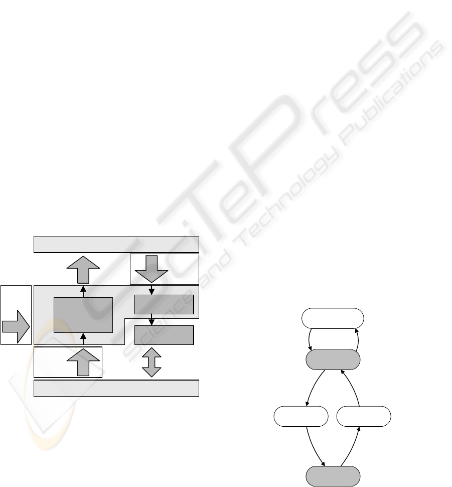
To fulfil these requirements the “P’n’P-Module” is
introduced. It acts as an intermediate between user
and devices. The operating mode of the P’n’P-
Module will be described in detail in the following
chapters. Figure 1 shows a block diagram of the
P’n’P-Module and its environment.
Generic HMI
data/
commands
device
descriptions
determine
functionality of
robot cell
executable
processes
generate
executable code
task
description
process
descriptions
Communication-Layer
P’n’P-Module
code executor
Figure 1: Block diagram of the P’n’P-Module and its
environment
5 DESCRIPTIONS
As shown in figure 1, three types of descriptions are
necessary:
Device Descriptions containing information
about the functionality and the programming
interface of devices.
Process Descriptions containing information
about the required functionality of a process
and the sequence of actions.
One user-defined task description containing
information about the sequence of processes
and according process parameters.
Information on the determination of the functionality
of the robot cell can be found in 0. Therefore, this
paper concentrates on the generation of executable
code out of descriptions of programming interfaces
of devices, the description of the sequence of actions
of processes and the user-defined task description.
5.1 Device Descriptions
The description of programming interfaces of
devices is realized in form of state charts, called
“Device State Charts”. Device State Charts can have
as many states as necessary, but depending on the
functional description of a device certain states are
mandatory. If the functional description of a device
contains a certain skill, the state chart must contain
certain mandatory state(s), e.g. if the functional
description of a gripper contains the skill “CanGrip”,
the Device State Chart of this device must contain
the states “open” and “closed”. Apart from these
mandatory states, the Device State Chart may have
other additional states that replicate special
properties of the device controller. Figure 2 shows
an exemplary Device State Chart of a gripper. The
states “configuring”, “opening” and “closing” are
additional states.
open
closed
opening closing
WaitFor:
XIRP:Request
<Open>
Send:
XIRP:Event
<gripper closed>
WaitFor:
XIRP:Request
<Close>
Send:
XIRP:Event
<gripper opened>
configuring
WaitFor:
XIRP:Request
<SetAngle>
Send:
XIRP:Event
<angle set>
Figure 2: Device State Chart of a simple gripper.
ICINCO 2008 - International Conference on Informatics in Control, Automation and Robotics
244
The transitions of the state chart describe the
device commands that triggers the state changes. In
the case of the bin picking test bed described in
chapter 7 UPnP and XIRP will be used as
communication protocols. Therefore the transitions
of the Device State Charts describe device specific
UPnP and XIRP communication to control the
devices.
Several languages exist to describe state charts.
One of them is SCXML 0. SCXML allows the
concurrent execution of parallel state charts and their
synchronization and is therefore well suited for the
use in Device State Charts.
Device State Charts are a mandatory part of
device descriptions in order to generate the
necessary sequence of commands to reach certain
states – that means, to execute a certain task.
5.2 Process Descriptions
General Process State Charts describe the states the
involved devices have to reach, their order and
synchronizations that must be taken into account.
They are the counterpart of Device State Charts.
General Process State Charts have the purpose of
describing the sequence of actions of a certain
process. “General” means that they describe this
sequence independent of the devices actually used
and therefore independent of their specific
programming interfaces. Therefore, they must
describe which states must be reached by the devices
in which order to execute a certain action, but they
must not describe how these states can be reached as
this depends on the devices actually used. General
Process State Charts consist of separate state
machines for each involved devices. These separate
state machines are synchronized where necessary,
e.g. to assure that a gripper is closed only after the
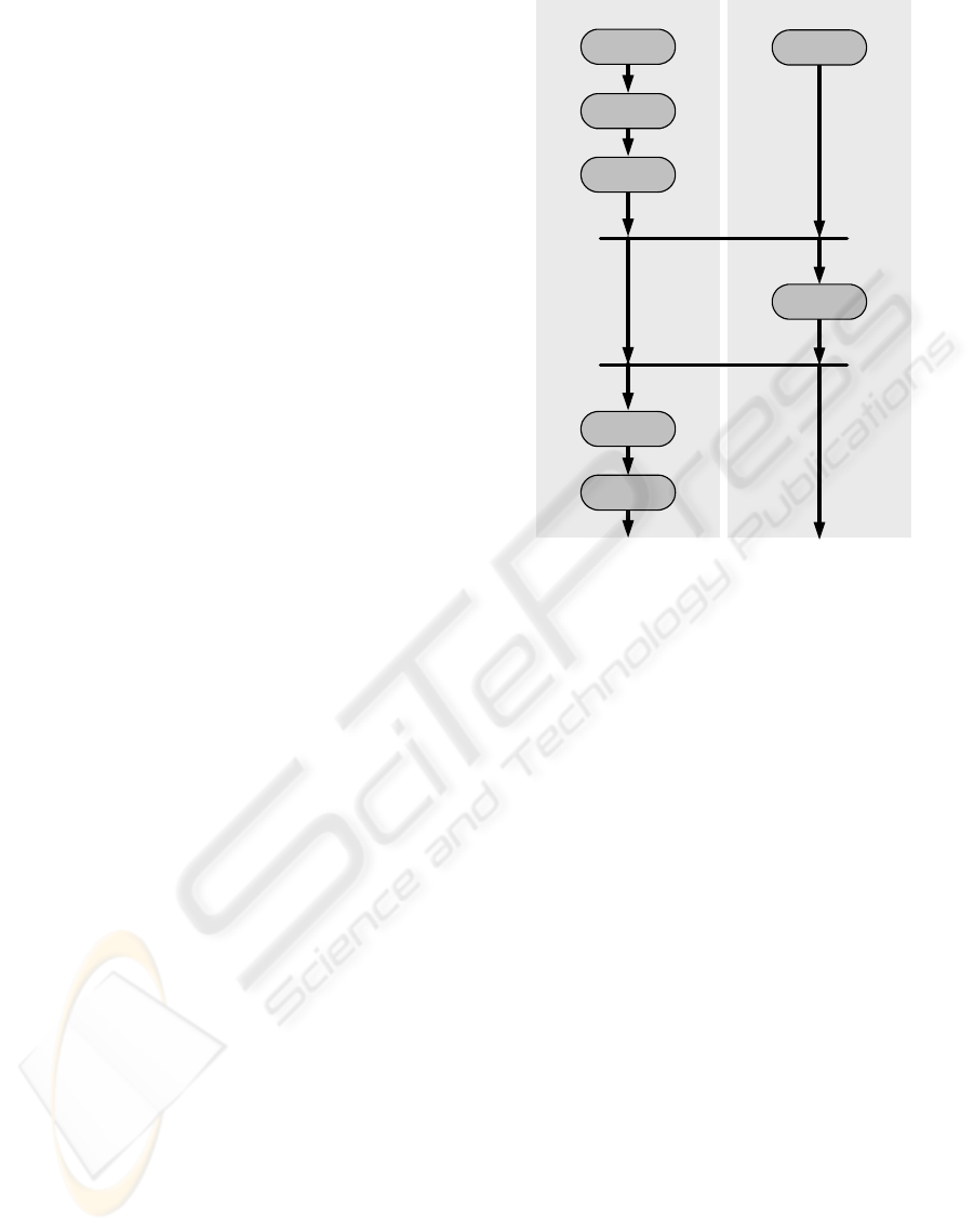
robot has reached the gripping position. Figure 3
illustrates the General Process State Chart of a
picking process.
General Process State Charts are expressed in
SCXML, too.
5.3 Task Description
The task description is defined by the user of the
robot cell on the Generic HMI as sequence of
process commands. The Generic HMI displays all
executable processes to the user. The user defines a
sequence of processes and enters the corresponding
gripper state chartrobot state chart
open
closed
idle
move
idle
move
idle
Figure 3: General Process State Chart of a picking process.
process parameters like e.g. gripping force, picking
position or robot speed. For that purpose dialogs are
automatically generated out of the process
descriptions. It is either possible to enter the required
process parameters directly on the HMI or, if
available, with the help of input devices. Positions
could e.g. be taught with lead through programming
if the robot is equipped with a force torque sensor
and the controller supports lead through
programming.
6 GENERATION OF
EXECUTABLE CODE
In order to run the task defined by the user code has
to be generated that can be executed by the code
generator (see figure 1). This code generation
consists of two steps. First, General Process State
Charts and Device State Charts are combined to
(device-) Specific Process State Charts. Second, the
Specific Process State Charts are concatenated
according to the user-defined task description to a
Task State Chart. In this Task State Chart, the user-
defined process parameter values are included.
Figure 4 illustrates the workflow.
AUTOMATIC GENERATION OF EXECUTABLE CODE FOR A ROBOT CELL USING UPNP AND XIRP
245
Generation
of Task State
Chart
Task State
Chart
(executable)
Specific
Process
State Charts
Task
Description
Device
State
Charts
General
Process
State Charts
Generation of
Specific
Process
State Charts
Figure 4: Workflow to generate executable code.
6.1 Generation of Specific Process
State Charts
Specific Process State Charts are generated out of
General Process State Charts by adding device
commands to the transitions.
Therefore, the states of the General Process State
Chart are mapped to states of the Device State
Charts of the used devices. The mapping is possible
because the states of the General Process State
Charts and the states of the Device State Charts are
related by an ontology. The device commands are
then added stepwise by searching a path in the
Device State Chart for each Transition in the
General Process State Chart. This path including all
states, transitions and device commands in between
is then inserted into the General Process State Chart.
Once this path-search has been done for a whole
General Process State Chart, the result is a (device-)
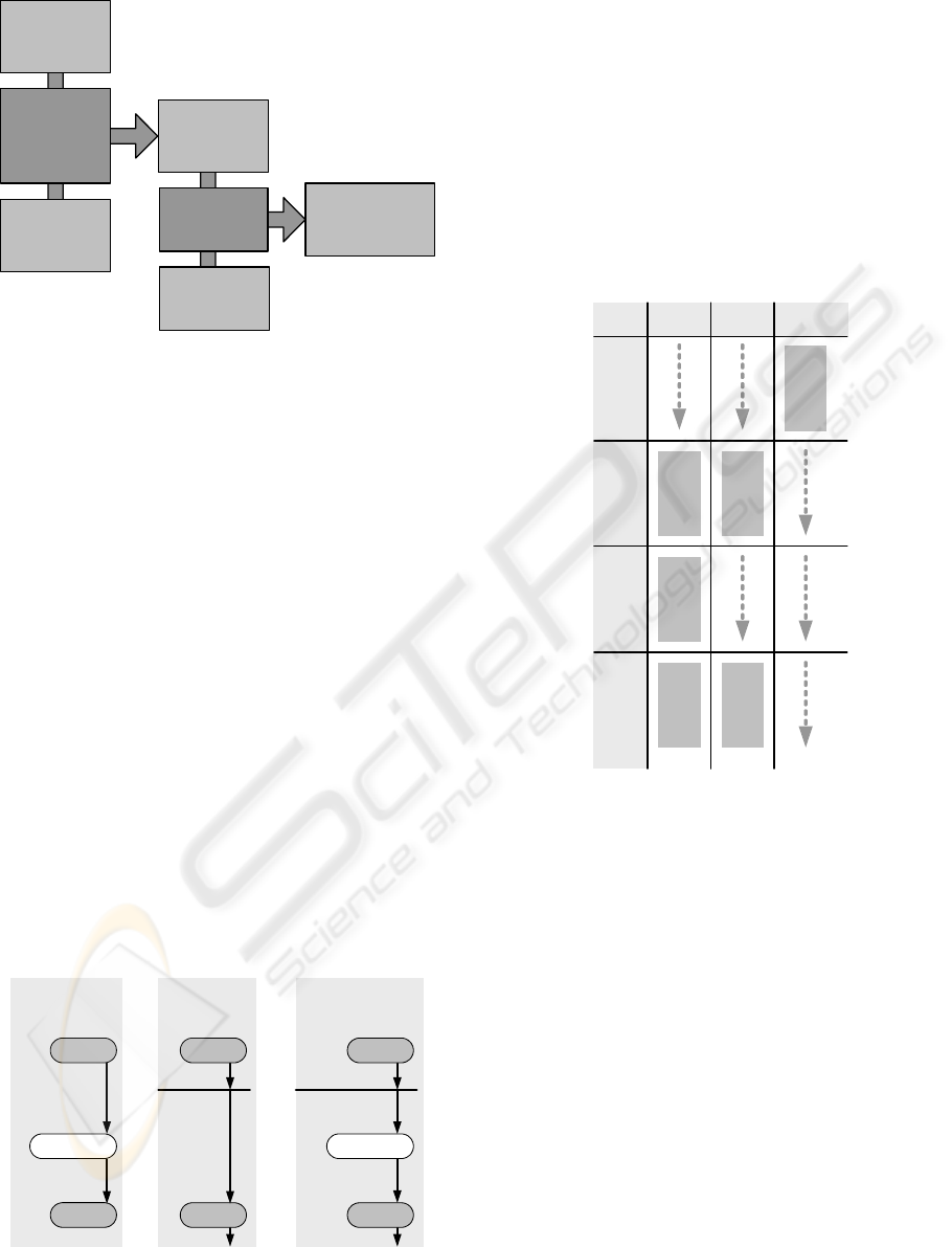
Specific Process State Chart. Figure 5 illustrates this
approach exemplary using the Device State Chart
shown in figure 2 and the Process State Chart in
figure 3.
Part of resulting
Specific Process
State Chart
open
closed
opening
Extract from
General Process
State Chart
open
closed
Extract from
Device State
Chart
closed
opening
open
+=
Send:
XIRP:Request
<Open>
Send:
XIRP:Event
<gripper closed>
WaitFor:
XIRP:Request
<Open>
WaitFor:
XIRP:Event
<gripper closed>
Figure 5: Generation of Specific Process State Chart out of
Device State Chart and General Process State Chart.
6.2 Generation of Task State Chart
To generate the Task State Chart, the Specific
Process State Charts are concatenated according to
the task description. If a process does not involve a
device, this device stays in the last state of the
previous process. Finally, the user-defined process
parameters are included. Result is a state chart
containing device commands of the used devices
that can be executed. Figure 6 shows an example of
a Task State Chart.
Place
process
Move
process
Pick
process
GetPartPos
process
State chart
of robot
State chart
of gripper
State chart
of camera
State chart
of robot
State chart
of robot
State chart
of gripper
robot gripper camera
Figure 6: Generation of Task State Chart by concatenating
processes.
While concatenating the processes, a basic
plausibility check is performed to assure that only
processes with matching final and start states are
attached. This plausibility check assures e.g. that the
gripping process shown in figure 3 cannot be used
without in between opening the gripper again in
some other process. In this way some errors of the
user defined Task Description can be detected.
6.3 Executing the Task State Chart
The execution of the Task State Chart is done by the
code executor in the cell controller (see figure 1).
For each involved device, a state machine is
initialized with the start state of the first process.
From then on these state machines check cyclically
if the condition of a transition is fulfilled. If yes, a
state change is triggered and the state machines
ICINCO 2008 - International Conference on Informatics in Control, Automation and Robotics
246
switch to the next state. State changes of a device
can either be triggered by an incoming message
from that device, by a state change of another device
or by a transition without a transition condition.
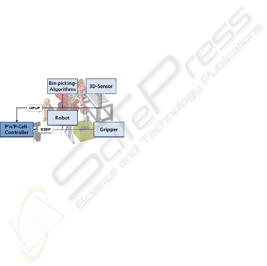
7 TEST BED BIN PICKING
The presented concept will be realized as test bed in
a bin picking robot cell. This cell consists of the
following devices:
Robot
Gripper
3D-Sensor
PC that runs the bin picking algorithms
All these devices are connected to a cell controller.
The cell controller runs the P’n’P-Module with the
described functionality. Figure 7 illustrates the
underlying control architecture.
Figure 7: Control Architecture of the bin picking cell.
All devices have their own controller that offers a
programming interface to access their functionality.
This programming interface is accessible either via
XIRP or the UPnP communication protocol.
Because both protocols support automatic discovery
and initialization of communication, the devices are
integrated into the cell controller without manual
configuration effort. Then, description files
containing the Device State Chart are loaded into the
P’n’P-Cell-Controller. The P’n’P-Cell-Controller
uses these descriptions to evaluate the cell
functionality and – after the user has defined a task –
generate and execute code as described in this paper.
8 CONCLUSIONS AND
OUTLOOK
The presented concept allows programming of a
robot cell without knowing details about the
underlying programming interfaces and
communication protocols and therefore permits
users with little knowledge of (robot) programming
to use robots. The user has to combine and
parameterize the processes but does not need to use
device commands. To facilitate the parameterization,
intuitive input devices can be integrated into the cell
controller.
The abstraction layers introduced to achieve this
goal furthermore allow easy exchange of devices
with different programming interfaces and
communication protocols as long as they offer the
same functionality.
The concept should help users in a SME
environment to define typical machine tending or
part handling tasks that do not require closed control
loops extending over several devices as the present
concept cannot cope with real time requirements.
One possible solution would be to include
mechanisms into the communication layer to support
real-time provided that real-time communication
protocols are used. Another, more advanced
approach would be to establish direct real-time
connections between devices that need to exchange
time-critical data. This approach would impose new
requirements on the devices and the underlying
network.
Another possibility to further advance the
presented concept is to upgrade the plausibility
check described in chapter 6.2. The available
information about the meaning of processes and
states could be used to not only detect task definition
errors, but also make suggestions to the user on how
to correct them.
A third advancement of the presented concept
could be an upgrade of the code executor. At the
moment it executes the generated Task State Chart
sending single commands to devices to trigger
actions. Because state charts are a very general way
of representing programs, the Device State Chart
could be used to generate complete programs for
single devices using transformation rules. This
would allow generating e.g. a program for a robot,
downloading it and running it on the robot controller
thus significantly reducing the communication
effort.
The bin picking test bed will give the opportunity
to prove the presented concept, to draw conclusions
about its strengths and weaknesses and by this
means decide about the next steps.
AUTOMATIC GENERATION OF EXECUTABLE CODE FOR A ROBOT CELL USING UPNP AND XIRP
247

ACKNOWLEDGEMENTS
This work has been funded by the European
Commission’s Sixth Framework Program under
grant no. 011838 as part of the Integrated Project
SMErobot
TM
.
REFERENCES
World Robotics 2007, IFR Statistical Department.
http://www.smerobot.org
Papas homepage: http://www.projekt-papas.de
UPnP Device Architecture; Version 1.0; 8.6.2000.
Downloadable from the UPnP-Forum: http://
www.upnp.org
VDMA Einheitsblatt 66430-1: XML-basiertes
Kommunikationsprotokoll für Industrieroboter und
prozessorgestützte Peripheriegeräte (XIRP) - Teil 1:
Allgemeine Vereinbarungen.
Riedl, M.; Simon, R.; Thron, M.: EDDL – Electronic
Device Description Language. München, Oldenburg
Industrieverlag, 2002.
OWL Web Ontology Language Overview, 10.4.2004.
Downloadable from W3C: http://www.w3.org/
TR/owl-features/
Berners-Lee, T.; Hendler, J.; Lassili, O.: The Semantic
Web, Scientific American, 17.1.2001.
SmartKom homepage: http://www.smartkom.org/
Torge, S., Hying, C.: Realizing Complex User Wishes
With a Function Planning Module. In: SmartKom:
Foundations of Multimodal Dialogue Systems. Berlin.
Heidelberg. Springer Verlag, 2006.
Naumann, M.; Wegener, K.; Schraft, R. D.: Control
Architecture for Robot Cells to Enable
Plug’n’Produce. In: Proceedings of ICRA 2007.
State Chart XML (SCXML): State Machine Notation for
Control Abstraction 1.0, W3C Working Draft,
24.1.2006. Downloadable from W3C: http://
www.w3.org/TR/scxml/
ICINCO 2008 - International Conference on Informatics in Control, Automation and Robotics
248
