
ANALYSIS OF REMS GTS ERRORS DUE TO MSL ROVER AND
MARTIAN ENVIRONMENT
Eduardo Sebastián, Carlos Armiens and Javier Gomez-Elvira
Lab. de Robótica y Exploración Planetaria, Centro de Astrobiología, Ctra. Ajalvir Km.4, Torrejón de Ardoz, Spain
Keywords: Environmental monitoring, infrared temperature detection and sensor error sources.
Abstract: This paper analyses the external sources of error of the REMS GTS, a contactless instrument to measure
ground temperature that is part of the payload of the NASA MSL mission to Mars. Some environment
properties such us atmosphere opacity, solar radiance, ground emissivity and rover IR emissions are studied,
determining GTS characteristics. The article also proposes a simplified geometrical and thermal model of
the rover and environment in order to evaluate and quantify their influence in ground temperature
measurements. Finally, the article summarizes simulation results and provides solutions in order to improve
sensor accuracy.
1 INTRODUCTION
The GTS (Ground Temperature Sensor), one of the
REMS (Rover Environmental Monitoring Station)
instruments, is mainly dedicated to measure the
brightness temperature of Martian surface, using
three thermopiles detectors in three infrared IR
bands, and looking directly at the ground. The
selected channels are 8-14μm, 16-20μm and 14.5-
15.5μm.
In general it can be said that two error sources
are associated with contactless temperature
measurements. On the one hand internal sources, all
those related with the sensor, the amplifying
electronics, and also errors associated with
calibration and sensor degradation. On the other
hand we have the errors due to the environment. In
the case of the REMS GTS the environment shows
difficulties because of the uncertainty in Martian
surface emissivity, reflections from the rover and the
Sun, and atmosphere absorbance.
The main objective of this paper is to justify the
GTS design based on environment restrictions, as
well as to obtain a thermal model of the rover and
the environment in order to analyse and correct the
errors in ground temperature determination.
The paper is organized as follows; section 2
introduces briefly the REMS GTS; section 3
describes the environmental sources of error,
including a simplified radiation model of MSL
rover. Section 4 shows simulations to evaluate
environment influence, using the proposed model.
Finally, section 5 summarizes the results.
2 REMS GTS DESCRIPTION
REMS is an environmental station designed by the
Centro de Astrobiología with the collaboration of
national and international partners (CRISA/EADS,
Universidad Politécnica de Cataluña (UPC) and
Finish Meteorological Institute (FMI)), which is part
of the payload of the MSL (Mars Science
Laboratory) NASA mission to Mars, figure 1. This
mission is expected to launch in the final months of
2009, and mainly consists of a rover with a complete
set of scientific instruments.
Figure 1: NASA MSL rover.
205
Sebastián E., Armiens C. and Gomez-Elvira J. (2008).
ANALYSIS OF REMS GTS ERRORS DUE TO MSL ROVER AND MARTIAN ENVIRONMENT.
In Proceedings of the Fifth International Conference on Informatics in Control, Automation and Robotics - SPSMC, pages 205-210
DOI: 10.5220/0001505702050210
Copyright
c
SciTePress
The rover main body hosts the electronics
associated with the whole set of instruments, rover
communications and control systems. Additionally,
it includes the RTG (Radioactive Temperature
Generator) which is the rover energy source. The
RTG extra heat is used by rover thermal designers to
warm the rover body in order to keep alive the
electronics inside.
The GTS shall be mounted in one of the REMS
booms, which is placed in the rover mast at 1.6m
height and hosts the electronics dedicated to amplify
the thermopiles signals. The GTS includes an in-
flight calibration system without moving parts,
whose main goal is to compensate the sensor
degradation due to the deposition of dust over its
window (Sebastián and Gomez-Elvira, 2007). To
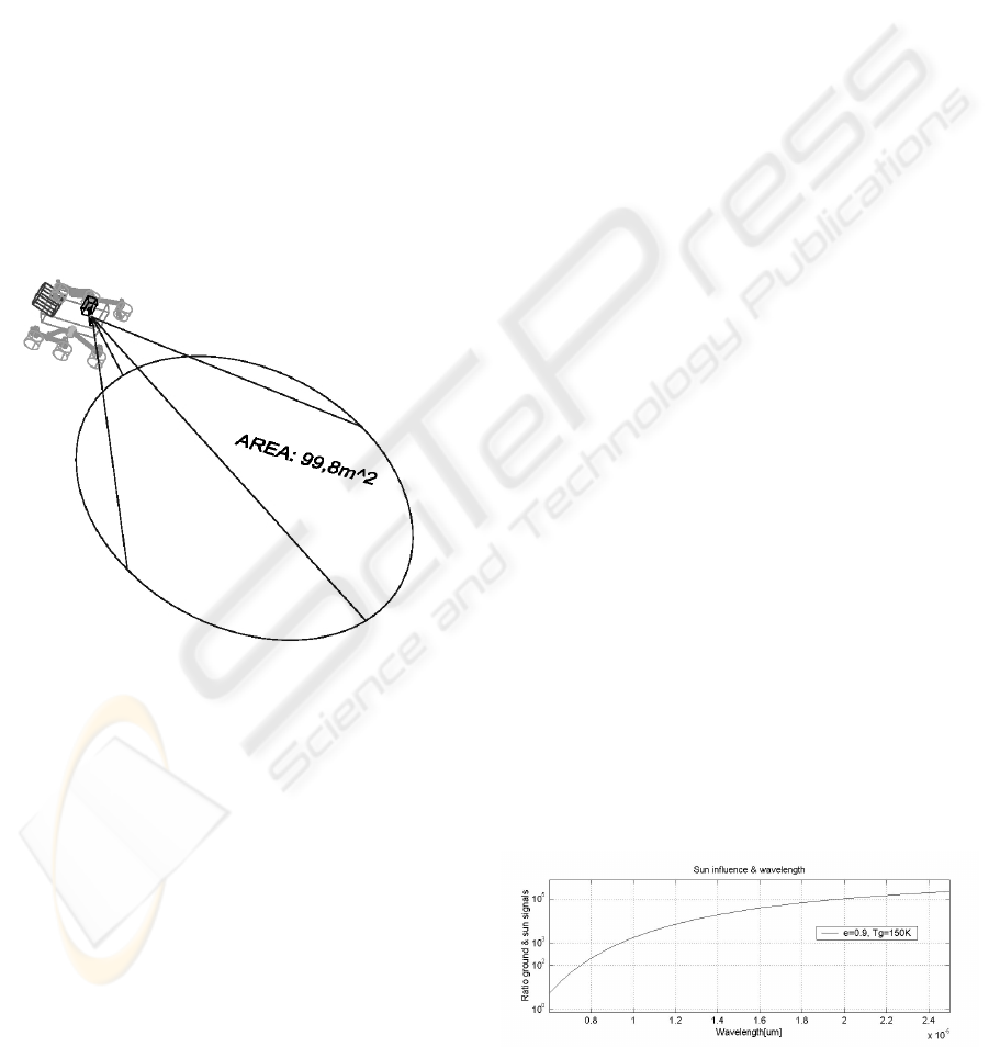
avoid local effects, the GTS focuses a large surface
area of around 100
2
m, shown in figure 2, measuring
the average temperature. This are is far enough from
the rover as to minimize its influence.
Figure 2: REMS GTS FOV and MSL rover simplified
draft.
3 GTS ERRORS DUE TO
MARTIAN ENVIRONMENT
Contactless temperature measurements are based on
the integration of the IR radiation coming from a
body. This radiation depends mainly on three
factors: The temperature of the focused area, the
emissivity
ε
of its surface, or what is the same the
capacity of the body to emit IR energy, and finally
the reflectivity r of its surface, that shows how the
body reflects energy coming from the environment.
For the characteristic temperatures of Mars the
emitted radiation falls mostly in the IR range.
Following Wien's law, the maximum of the
blackbody spectral radiance for a given temperature
is given by
λ
max
[μm]=2898/T[K]. If the maximal and
minimal Martian temperatures are T
max
=293K and
T
min
=150K then the sensor is designed to work
optimally in the range from 9.9μm to 19.3μm.
3.1 Atmosphere Transmission
Windows
The Martian atmosphere consists mostly of CO
2
,
which has a strongly absorbing band centred at
15μm. The CO
2
in the column of air within the cone
of view may also act as absorber and emitter (notice
that the air is generally at a very different
temperature from the ground) around the band.
Additionally, water molecules have a very strong
absorption at 1.45μm, and a weak absorption at
6.27μm (Martin, 1986).
3.2 Reflected Solar Radiance
Since the typical emissivities of Martian soils are
different from one, the IR Solar radiation shall be
added up to ground emissions (Lienhard and
Lienhard, 2006). Assuming that in the IR the Sun
radiance on the Martian surface is equal to the one
on top (inside atmosphere transmission windows),
and that the Martian ground IR reflectivity r=1-
ε
,
with
ε
the emissivity, is bounded to 0.1, one can
obtain the reflected flux as E
reflected
=r·E
sun
. The solar
flux on Mars surface is, F
sun
=E·(R
s
/D)
2
with
R
s
=6.96x10
8
m the Sun radius, D=1.52·1AU=
1.52·1.5x10
12
m the Sun to Mars distance, and where
E is the radiance of a blackbody emitting at a
temperature T=6000 K (Vázquez et al., 2005).
The measurements must be performed in a range
where the ratio of IR radiance emitted by the
Martian surface to the solar IR radiance reflected by
the Martian surface is significantly greater than one.
For instance, figure 3 shows that above 8μm the
solar reflected radiance is smaller than 0.5% for the
lower ground temperature, T
g
=150K.
Figure 3: Ratio ground signal/sun radiance vs. wavelength.
ICINCO 2008 - International Conference on Informatics in Control, Automation and Robotics
206
Therefore, the GTS channels 8-14μm and 16-
20μm are selected taking into account the optimum
wavelength range from Wien’s law, but trying to
avoid the atmospheric absorption bands and the
wavelengths in which solar radiation cannot be
neglected. Each channel is specialised in the
measure of a temperature range where the higher
S/N ratio, based on the Planck’s law, is achieved
(Vázquez et al., 2005). The other GTS band 14.5-
15.5μm shall measure the temperature of Martian
atmosphere using for that the CO
2
emission band.
3.3 Reflected Rover Radiance
The MSL rover is a source of error for the GTS,
since some parts of it are subjected to temperatures
over the ground. These rover elements are mainly
the RTG and the rover body, which can reach
temperatures 200K and 50K over the atmosphere,
respectively. These elements are painted using high
emissivity paint, and their temperature shall be
recorded on line during Martian operation.
In order to evaluate rover influence as a source
of error in the determination of ground temperature
it is necessary a thermal conduction and radiation
model of Martian environment. In (Lee, 2006) the
heating process of ground surface by thermal
conduction due to the RTG is studied. The results
show a neglected influence in the area focused by
the GTS. On the other hand, figure 2 shows a
simplified geometrical representation of the
environment (GTS thermopiles, rover, atmosphere
and Martian surface), from which rover radiance
reflected on the ground can be estimated based on a
radiation diagram. The radiation model considers
that the IR energy reflected by the ground is
completely diffuse.
Eg·eg
+
..
Es
+
..
Requç
Ea=0
+
..
Rg-a
Rg
Rg-s
Es
+
..
Rg-s
Eg
+
..
Es
+
..
Rg-s
Eg·eg
+
..
s
E
s
E
s
E
g
E
0=
a
E
gg
E
ε
·
gg
E
ε
·
sgg
FA
−
·
1
g
g
A
ε
−1
gg
g
A
ε
ε
·
1−
sgg
FA
−
·
1
sgg
FA
−
·
1
agg
FA
−
·
1
Eg·eg
+
..
Es
+
..
Requç
Ea=0
+
..
Rg-a
Rg
Rg-s
Es
+
..
Rg-s
Eg
+
..
Es
+
..
Rg-s
Eg·eg
+
..
s
E
s
E
s
E
g
E
0=
a
E
gg
E
ε
·
gg
E
ε
·
sgg
FA
−
·
1
g
g
A
ε
−1
gg
g
A
ε
ε
·
1−
sgg
FA
−
·
1
sgg
FA
−
·
1
agg
FA
−
·
1
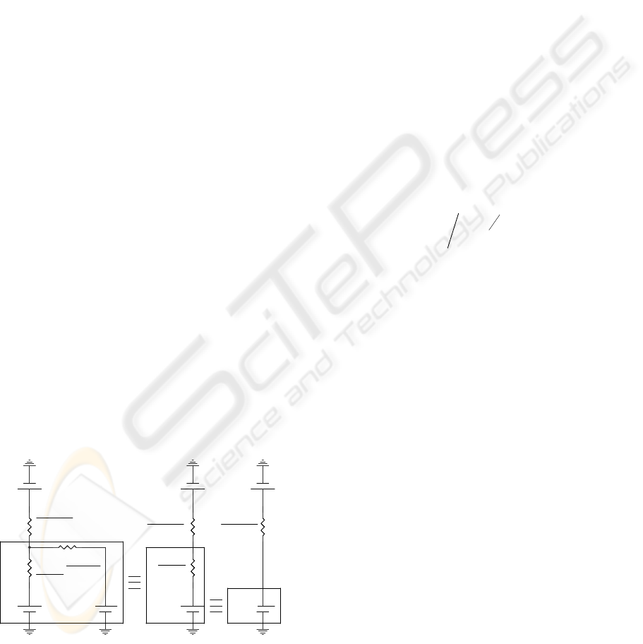
Figure 4: GTS and ground equivalent thermal circuit.
The first step in rover radiance influence analysis
considers an ideal situation in which the rover does
not exist. The circuit shown in figure 4 represents an
electrical analogy of the thermal model, in which
voltage generators and currents are equivalent to the
energy flux radiated by each body and the heat
exchange respectively and resistors represent surface
and geometry radiation resistances. The value of the
resistors depends on parameters such us the areas
and emissivities of the bodies, and the view factor
between them (Lienhard and Lienhard, 2006). The
atmosphere, as it was said before, is modelled as a
transparent body that does not emit energy inside the
measurement wavelengths, E
a
=0. In this way, A
g
represents the area of the ground seen by the GTS,
ε
g
the emissivity of the ground, F
x-y
the view factor
between the bodies determined by the subscripts,
and finally E
x
represents the energy radiated by a
blackbody at the temperature of the body determined
by the subscript and inside the measurement band of
the thermopile. The subscript g is for ground, a is for
atmosphere and s is for the thermopiles. The
expression of E
x
follows Planck’s law and takes the
form,
[]
252
/1·2)·( mWdehcTE
X
KT
hc
x
∫
⎟
⎠
⎞
⎜
⎝
⎛
−=
λλλ
λ
(1)
where T(
λ
) is the thermopiles filter transmittance.
Figure 4 shows two successive simplifications of
the electrical circuit. The first one obtains an
equivalent circuit, assuming that the view factor F
g-a
is very close to the unit. This is reasonable because of
the small size of the thermopile and environment
geometry. The second simplification assumes two
things: first the view factor F
g-s
is very small and close
to zero, since the area of the thermopile compared with
the distance between the thermopile and the ground is
very small. Second,
ε
g
takes real values that go from
0.9 to 1. Thus, the equivalent resistor is dominated by
the value of the geometry resistance.
This circuit gives us means for calculating the
heat exchange between the environment and the
sensor, whose temperature (T
s
) is known. From it,
and based on GTS thermopiles sensibility G
s
[V/W],
the output voltage of the thermopiles (2) can be
obtained. This voltage shall be considered as the
GTS ideal output, and shall be compared with the
real one, once the rover is included in the thermal
model. The result of this comparison shall be the
error introduced by rover heated bodies. In addition
to that, equation (2) depends on the value of ground
emissivity,
ε
g
, which is an a priori unknown
parameter that introduces also uncertainty in ground
temperature determination.
ANALYSIS OF REMS GTS ERRORS DUE TO MSL ROVER AND MARTIAN ENVIRONMENT
207
EGV
Sout
Δ= ·
(
)
SggSgg
EEFAE −∈=Δ
−
···
(2)
The next step in rover influence analysis includes
the rover geometrical and thermal model. Figure 5
stars from a previous simplification of rover body
and RTG equivalent circuits. This simplification,
whose objective is to obtain the equivalent circuit
for these bodies and the atmosphere, is similar to the
carried out in figure 4 for Martian ground.
Es
+
..
Es
+
..
Eeq
+
..
Requ
(1-eg)/Ag
Rrtg-g
Rg-s
Rdeck-g
Rg-s
Eg·eg
+
..
Eeq
+
..
Edeck
+
..
Es
+
..
Ertg
+
..
Rg-s
s
E
s
E
s
E
bodybody
E
ε
·
gg
E
ε
·
equ
E
sgg
FA
−
·
1
g
g
A
ε
−1
sgg
FA
−
·
1
sgg
FA
−
·
1
RTGgg
FA
−
·
1
equ
E
RTGRTG
E
ε
·
g
g
A
ε
−1
bodygg
FA
−
·
1
I1
I2
Es
+
..
Es
+
..
Eeq
+
..
Requ
(1-eg)/Ag
Rrtg-g
Rg-s
Rdeck-g
Rg-s
Eg·eg
+
..
Eeq
+
..
Edeck
+
..
Es
+
..
Ertg
+
..
Rg-s
s
E
s
E
s
E
bodybody
E
ε
·
gg
E
ε
·
equ
E
sgg
FA
−
·
1
g
g
A
ε
−1
sgg
FA
−
·
1
sgg
FA
−
·
1
RTGgg
FA
−
·
1
equ
E
RTGRTG
E
ε
·
g
g
A
ε
−1
bodygg
FA
−
·
1
I1
I2
Figure 5: GTS, rover body and ground equivalent thermal
circuit.
The equivalent resistance of the squared area of
figure 5 can be easily calculated, assuming that view
factors between ground and rover body (F
g-body
) and
ground and RTG (F
g-RTG
) take values close to zero.
Thus, the resistor inside the ground branch of the
circuit is much smaller than the others, and its value
dominates. Equally, the calculation of the equivalent
generator of the squared area E
equ
needs to solve the
equations system (3) for I
1
and substitute its value in
(4). And finally, the second simplification follows
the same reasoning of figure 4.
()
⎥
⎦
⎤
⎢
⎣
⎡
⎥
⎥
⎥
⎥
⎥
⎦
⎤
⎢
⎢
⎢
⎢
⎢
⎣
⎡
+
−
−
+∈−
=
⎥
⎦
⎤
⎢
⎣
⎡
∈−∈
∈−∈
−−
−−
−
−−
−
2
1
···
1
·
1
·
1·1
··
··
I
I
FFA
FF
FA
FAFA
F
EE
EE
bodygRTGgg
bodygRTGg
RTGgg
RTGggRTGgg
RTGgg
bodybodyRTGRTG
RTGRTGgg
(3)
(
)
gg
g
g
equ
E
A
IE ∈+
∈−
−= ·
1
·
1
(4)
Newly, equation (4) shows a dependency of
ground emissivity,
ε
g
. In this case temperatures,
emissivities and view factors of rover body and RTG
appear additionally in the equation as a new source
of uncertainty.
4 SIMULATIONS ON ROVER
AND EMISSIVITY INFLUENCE
The development of practical test with a real or
scaled model of the MSL rover is extremely costly,
since Martian temperature ranges requires the usage
of complicate climatic chambers. From this point of
view, this chapter is dedicated to develop
preliminary simulations to evaluate or obtain a upper
bound of rover and ground emissivity influence in
the determination of Martian surface temperature.
The simulations are based on the GTS thermal
radiation model described in the previous section.
Then, to apply the model, the values of the view
factors and the ground area covered by the sensor
are required. In order to obtain practical data,
simulations using the software package Thermal
Desktop and a simplified geometrical model of the
problem similar to the shown in figure 2, have been
carried out. The model assumes that the rover and
the ground are in a horizontal plane. The results are
shown in table 1. Additionally, it must be pointed
out that the value of the energy terms, E
x
, are
obtained based on thermopiles practical data
(Sebastián and Gomez-Elvira, 2007).
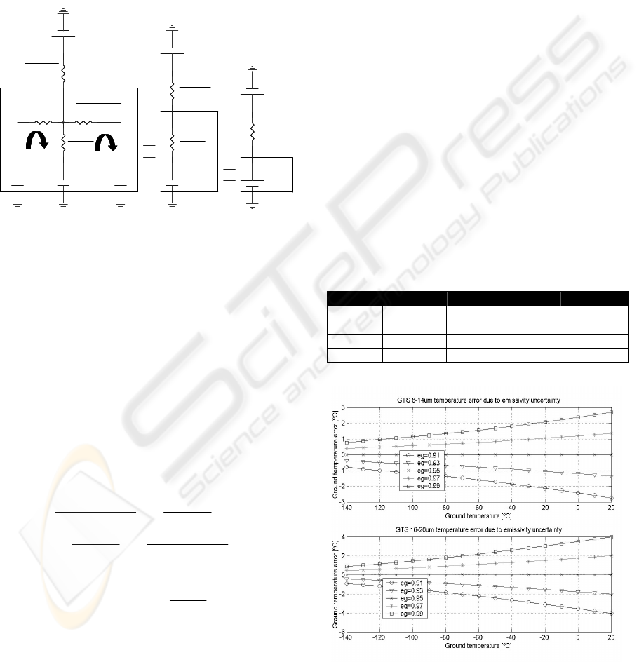
Table 1: REMS GTS simulation data.
Body
ε
T A F
g-x
GTS 1 T
g
+20K 1mm
2
1.99x10
-9
Ground 0.91-0.99 T
g
99.8m
2
Rover 0.8 T
g
+70K 0.0021
RTG 0.8 T
g
+220K 0.00101
Figure 6: Ground temperature determination error due to
ground emissivity uncertainty, supposing an emissivity
value of 0.95.
ICINCO 2008 - International Conference on Informatics in Control, Automation and Robotics
208
The first simulation, figure 6, tries to analyse the
error associated to the determination of ground
temperature, generated by the uncertainty in ground
emissivity without taking into account rover effects.
Temperature error dada are provided for the
thermopiles 8-14μm and 16-20μm, considering an a
priory value for ground emissivity of 0.95. The
simulation is run for a possible range of Martian
ground temperatures, from 133K to 293K.
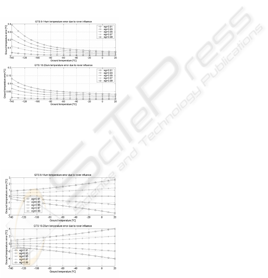
The second simulation, figure 7, analyses the
error introduced by rover body and the RTG. In this
case, ground emissivity is assumed to be known.
Figure 7: Ground temperature determination error due to
rover influence, supposing known values for ground
emissivities.
Finally, the last simulation, figure 8, includes the
errors associated to ground emissivity uncertainty
and rover body and RTG reflections, supposing a
value for the ground emissivity of 0.95.
Figure 8: Ground temperature determination error due to
rover influence and ground emissivity uncertainty,
supposing an emissivity value of 0.95.
5 CONCLUSIONS AND FUTURE
WORK
The selection of GTS measurement bands is
conditioned by Martian atmosphere optical
properties, ground temperatures as well as taking
into account solar reflected radiance, in order to
minimize or neglect the associated errors.
The REMS GTS location and orientation has
been selected in order to minimize rover influence,
due to the heating process of ground surface by
thermal conduction and rover indirect view
throughout ground reflected radiance. Additionally,
GTS field of view has been maximized in order to
increase signal to noise ratio, avoiding rover direct
vision.
Simulations on ground emissivity uncertainty
have shown an important error contribution in
ground temperature determination, reaching error
values of ±4K. This error is initially compliant with
GTS instrument required accuracy of ±5K,
nevertheless is so big that its contribution to the total
error budget must be reduced.
A possible solution to deal with this error resorts
to study the emissivity of similar soils to those found
on Mars. MSL mission includes a set of payload
instruments capable of providing detail information
about Martian soils composition. Thus, after
knowing the king of soil in which the rover is
operating, the studied emissivity value can be
applied.
Colour pyrometry techniques (Joners and
Gardner, 1980) are other possible solution, which
could be implemented in order to estimate ground
temperature and emissivity at the same time. A
possible algorithm consists of four equations (5)
with four unknown variables: the emissivities
ε
g
8-14
and
ε
g
16-20
, and ground temperatures T
g1
and T
g2
. The
first two equations are obtained from the equation
(2), particularized for the measurement bands (8-
14μm, 16-20μm). To complete the four equations a
new measurement for a different ground temperature
is required, while rover remains still in order to
assume constant the value of ground emissivity.
(
)
(
)
() ( )
2016
2
2,2016148
2
2,148
2016
1
1,2016148
1
1,148
,,
,,
−−−−
−−−−
∈=∈=
∈=∈=
gg
Tg
equgg
Tg
equ
gg
Tg
equgg
Tg
equ
TfETfE
TfETfE
(5)
The other source of error studied in this article,
rover over temperature effect, generates temperature
errors below ±0.4K, for the worst ground
temperature conditions. Initially, this error could be
neglected in comparison with others, and the
ANALYSIS OF REMS GTS ERRORS DUE TO MSL ROVER AND MARTIAN ENVIRONMENT
209

required GTS accuracy. However, this study
assumes some simplifications on environment
geometry and ground emissivity. For instance, frost
formation over the ground or different ground tilts
could modify rover reflectance, increasing error
contribution.
Therefore, an algorithm to compensate rover
influence could be required. The algorithm shall
necessarily be based on the model described in
section 3, subtracting in (4) the effect of the
undesired energy rover terms and solving for E
g
. In
order to do it, an estimation of
ε
g
, A
g
, F
g-body
and F
g-
RTG
, and the real temperatures of rover bodies are
required. The topography of the surface seen by the
sensor modifies the view factors between the
different environment objects. Thus, in order to
carry out this geometrical analysis it is necessary to
have a three-dimensional image of rover
environment, as well as rover position and
orientation. These data shall be provided by NASA.
Afterwards, they shall be used to obtain more
accurate view factors and areas, or just as a quality
control system to confirm the validity of the results.
For instance, CO
2
frost, shadows with different
ground temperature, or extreme ground tilts are
different circumstances to be detected.
A more rigorous analysis of rover influence and
a possible improvement in this algorithm must
include the sensibility of GTS versus the radiation
incident angle. Initially, the whole surface area seen
by the sensor is weighted equally, this is reasonable
for ground emitted radiation since the whole ground
is supposed to be at the same temperature.
Nevertheless, several small differentials of area, in
which the GTS sensibility is different, could be
considered instead of a unique ground area. So, IR
energy coming from the rover and reflected in these
differentials of area must be weighted considering
GTS sensibility. Equation 6 shows how the
geometrical resistor between ground and RTG
would be calculated,
∑
−RTGiggii
FAg ··
1
(6)
where A
gi
is the differential of area i, F
g-RTGi
is the
view factor between the RTG and the differential of
area i, and g
i
is the weighting factor that considers
GTS sensibility. Sensibility depends on the incident
angle of the radiation and fulfils
∑
=
giig
AgA ·
.
Finally, the simplify model described in this
article must be confirmed using a specialized
software such us Thermal Desktop, evaluating the
global behaviour of the model and not only for
obtaining the value of the view factors.
ACKNOWLEDGEMENTS
The authors would like to express special thanks to
all members of the REMS project who are
collaborating in the development of the GTS.
REFERENCES
Joners T.P. Gardner J.L. 1980. Multi-wavelength radiation
pyrometry where reflectance is measured to estimate
emissivity. Phys. E: Sci. intrum., 1, 3006-319.
Lienhard IV J.H. and Lienhard V. J.H. 2006. A Heat
Transfer Textbook. web.mit.edu,3
rd
edition.
Lee C. J. 2006. MSL study on RTG-to-Ground Interaction
Zone. Applied Sciences Laboratory, Inc. internal
report.
Martin T.Z. 1986. Thermal infrared Opacity Of The Mars
Atmosphere. Icarus, 66, 2-21.
Sebastián E. and Gomez-Elvira J. 2007. Preliminary tests
of the REMS GT-sensor, In ICINCO'07 International
Conference on Informatics in Control, Automation and
Robotics, Angers (France).
Vázquez L., Zorzano M.P., Fernández D., McEwan I.
2005. Considerations about the IR Ground
Temperature Sensor. CAB, REMS Technical Note.
Madrid.
ICINCO 2008 - International Conference on Informatics in Control, Automation and Robotics
210
