
ADOPTING BUILDING AUTOMATION IN WEBLABS
Analysis of Requirements and Solutions
Ricardo J. Costa, Gustavo R. Alves
LABORIS / Polytechnic Institute of Porto - School of Engineering (ISEP), Porto, Portugal
Domingos S. Santos
Polytechnic Institute of Porto - School of Engineering (ISEP), Porto, Portugal
Keywords: Remote Experimentation, Weblab, Domotic System, KNX.
Abstract: Several companies have been developing domotic Stds. for building automation, enabling users to locally
and remotely control several home devices, like: lights, power sockets, heating, ventilation, and air condi-
tioning systems, among others. Besides contributing to improve the building comfort, these Stds. may also
be adopted for other purposes, namely in weblabs used in sciences and engineering remote experiments. To
increase the sense of immersion in weblabs, we identify domotic Stds. as a standard solution for turning
on/off the power infrastructure and controlling the light and temperature conditions of the physical space
where a specific experiment may run, thus approaching the sense of being in the lab facilities while access-
ing them through the corresponding weblab interface. After identifying the added value to weblabs in terms
of power savings and in the control of the environmental conditions, it is presented a proof-of-concept (im-
plemented with an adopted domotic system bus), which enables the control of an halogen lamp and a power
socket, using a specific Web interface.
1 INTRODUCTION
Weblabs are used for educational purposes since the
mid 90’s. According to Aktan et al. (Aktan et al.,
1996), it was maybe in 1996 the first time an under-
graduate weblab has been made fully accessible
through the Internet. This solution contributed to the
appearance of the Remote Experimentation concept,
defined as a distance learning area that enables the
remote control of real experiments using computers
connected to the Internet. Since weblabs require
specific resources to enable a remote access, several
solutions for harmonizing the software and hardware
used for implementing them have already been pro-
posed and described. However, the existence of
many different technologies difficults the choice for
a standard approach. Usually, when a specific we-
blab is required, an immediate and particular techni-
cal solution is adopted for its development. More-
over, due to the specificity of each solution, usually
only qualified people are able to develop one, which
partially justifies that almost all weblabs fall into the
engineering domain (Jing Ma and Jeffrey, 2006).
Thus, harmonization at hardware and software levels
is an important aspect to take into consideration as to
facilitate the construction of standard and well de-
fined weblabs. By following a standard architecture,
other aspects may be considered during a weblab
implementation, namely the environment of the
physical space occupied by it and the power infra-
structure. Controlling these two common aspects to
all weblabs, further control facilities are given to
remote users, enabling them to control the place
where a specific experiment is running, like if they
were in that place, contributing to approach the in-
place lab facilities to weblabs. To implement these
aspects in any weblab, it is proposed the adoption of
a standard domotic system bus usually implemented
in smart houses, which will ease the control of all
the environmental conditions encountered in any lab.
In the next section of this paper we discuss some
requirements associated with weblabs, namely issues
concerning the control of the physical space (light
incidence and temperature) and the power sockets
where the lab devices are connected to; section 3
proposes an architectural solution, based on a domo-
279
J. Costa R., R. Alves G. and S. Santos D. (2008).
ADOPTING BUILDING AUTOMATION IN WEBLABS - Analysis of Requirements and Solutions.
In Proceedings of the Fourth International Conference on Web Information Systems and Technologies, pages 279-283
DOI: 10.5220/0001516702790283
Copyright
c
SciTePress

tic system bus, while section 4 describes the solution
adopted for our lab that enables remotely controlling
two specific devices (a halogen lamp and a power
socket). The paper ends with some considerations
about the work already done and future directions.
2 REQUIREMENTS
Each weblab requires a specific place to accommo-
date the apparatus, the measurement equipment and
the servers. Usually, those places have characteristic
light incidence, temperature and humidity condi-
tions, containing all the equipment power supplied.
The necessity to adopt a weblab to support the prac-
tical work, 24 hours per day, 7 days per week, has
consequences in the power consumption and in the
results obtained from the experiments. Then, spe-
cific attention should be paid to the physical envi-
ronment where an experiment is running, namely
with light and temperature conditions. Besides the
possibility of controlling the artificial light, it may
also be required to change the natural light incidence
by controlling the blinds of the physical space where
a specific experiment is running. In some cases tem-
perature control may also be required, because: 1)
some experiments use specific materials that change
with temperature conditions, and 2) some measure-
ment equipment may require a specific temperature
to work properly. This will lead to better results and
to avoid the damage of the equipment. An additional
requirement that should be considered is the ability
to switch off each device of the weblab, when not in
use. If possible of being done remotely, the all lab
may be switched off when a specific experiment
ends. Latter, when another experiment is starting,
the remote user may turn it on. This will contribute
to a reduction of the power consumption and hence
of the energy costs. Additionally, it may also be de-
sirable to reinitialize a certain device by applying an
off/on sequence. These suggestions/requirements
depend on whether the device and apparatus to be
switched off/on requires a setup procedure or not.
For example, it will not be reasonable to switch off
an Instrumentation Server used in a weblab by just
pulling out the plug from the power socket, because
it may damage the software installed on it. In this
case, it will be required to control remotely an UPS
(Uninterrupted Power Supply) to make a soft reset
or to turn the Instrumentation Server off. If all these
setup and reinitialization considerations are sup-
ported through remote control, then the technical
support, usually made by a technician, may be re-
duced or even suppressed, which also contributes to
reduce the weblab maintenance costs. Moreover,
switching off all devices and the apparatus, when not
in use, reduces the ageing effects, which also con-
tributes to the quality of the results obtained from
the remote experiments.
To address all the previous points, we propose using
a specific architecture with a standard domotic sys-
tem bus, usually implemented in smart houses. The
advantage of using a standard solution is that all
institutions currently supporting weblabs may
quickly adopt it with small development efforts.
3 PROPOSED ARCHITECTURE
Commonly, weblabs are idealized for specific ex-
periments. Although several weblab architectures
have been described in related literature, to the best
of our knowledge, few have considered the ability to
remotely control the physical space as well as the
power sockets where the lab devices connect to. At
this point two situations are common: 1) this re-
quirement is not even considered; 2) in-house spe-
cific solutions are used to tackle the problem. To
address both situations we propose weblab designers
to considerate the use of a standard domotic system
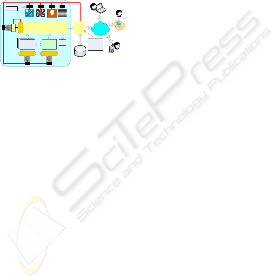
bus, in the way illustrated in figure 1. This proposed
architecture contains two servers: the Instrumenta-
tion Server and the Web Server, both connected
through an Intranet. All devices available in the we-
blab, namely the experiment apparatus, Webcams,
and the measurement equipment are controlled by
the Instrumentation Server that will sends/receives
basic signals to control and monitor each device. At
the same time, the Instrumentation Server transfers
information to/from the Web Server enabling the
interface between remote users and the lab. Another
relevant aspect presented in the proposed architec-
ture is the UPS. This unit is connected to the Instru-
mentation Server via a serial RS232 connection, and
to a power socket controlled by the domotic system
bus. By turning off this power socket, the UPS will
send a signal to the Instrumentation Server, instruct-
ing him to initiate a software shut down sequence.
This avoids the application under execution in the
Instrumentation Server, from being damaged be-
cause of a sudden power failure (i.e. an off com-
mand) or an improper shut down sequence. Users
must establish a Web connection to the Web Server
so they can download the Web interfaces designed
for a specific device (PC, PDA, Smart Phone or Mo-
bile phone), to control the weblab. The Web Server
should also contain the relevant pedagogical con-
tents, supported by a database together with a Vir-
WEBIST 2008 - International Conference on Web Information Systems and Technologies
280
tual Learning Environment both intending to keep e-
learning course contents (e.g. documents and im-
ages) together with specific tools for course man-
agement, like assessment tools and others. More-
over, since usually only one experiment is available
in a specific weblab, the Web Server should also
have an access management system, required to
handle simultaneous accesses (Ferreira and Cardoso,
2005).
Measurement
Instruments
Measurement
Instruments
Measurement
Instruments
Experiment
Instrumentation Server
Web
Cam
Web
Server
Blinds
Temperature
Lights
Power Supply Power Supply
Domotic BUS
WEB
PC
Mobile Phone
User
Weblab
UPS
RS 232
Power
Supply
Domotic BUS
PDA
Smart-Phone
VLE
Access
Management
System
Actuator
User
User
Database
(Pedagogical
Contents)
Fans
Figure 1: Suggested architecture to control the temperature
and light conditions plus the power infrastructure (power
sockets) of the weblab physical space.
Additionally, the Web Server should also control the
domotic system bus. For this purpose, it must be
coupled to the domotic system bus so that a software
layer installed in it may enable remotely controlling
all lab devices. This facility should be made by the
Web Server because it is the only device required to
be permanently turned on. Specific domotic devices
named actuators are directly connected to lamps,
temperature sensors, and other devices, and are
characterized by having a dedicated processor that
enables doing specific control tasks required for
each of those devices, like: increasing lights inten-
sity, open/close blinds, controlling the temperature
and so on. Besides controlling each device, the proc-
essor within the actuator has also the ability to un-
derstand a communication protocol, specific of the
domotic bus. By adopting this solution, the Web
Server will be free from the hard processing tasks.
This will facilitate the adoption of this architecture
for all weblabs, because it is not necessary to de-
velop the hardware, and the software will be much
easier to build. Besides, if we adopt a commercial
domotic system, which guaranties a well tested solu-
tion, user’s confidence to use the weblab will in-
crease. Based on these considerations, we imple-
mented a new layer that enables controlling some
devices used in our weblab.
4 IMPLEMENTED LAYER
A research of the most well known ‘de-facto’ stan-
dards available in the market for building automa-
tion lead us to adopt the KNX std. in our weblab.
Based on the communication stack of the EIB
(European Installation Bus) specification (which
justifies the use of KNX/EIB acronyms available in
some literature), KNX is the only open Std., being
both an European Std. (CENELEC/EN 50090 and
CEN/EN 13321-1) and a world Std. (ISO/IEC
14543-3), it is platform independent, guaranties in-
teroperability of products from different manufac-
turers and stands for high product quality guaranteed
by the KNX Association (KNX, 2007). Furthermore,
KNX has many products available in the market able
to be controlled with free software APIs (Applica-
tion Programming Interfaces). Thus, we adopted the
architecture presented in figure 1 (section 3) using
KNX devices, and we installed in the Web Server a
software layer to control the KNX system. Instead of
implementing the KNX protocol from the scratch,
we developed the software layer using a JAVA API
named CALIMERO developed by the Vienna Uni-
versity of Technology, Automation Systems Group
(Calimero, 2007). This API provides a set of meth-
ods to control the KNX bus communications and all
the connected devices. The next sub sections present
all the development aspects at both the hardware and
software levels.
4.1 Physical Devices and Configuration
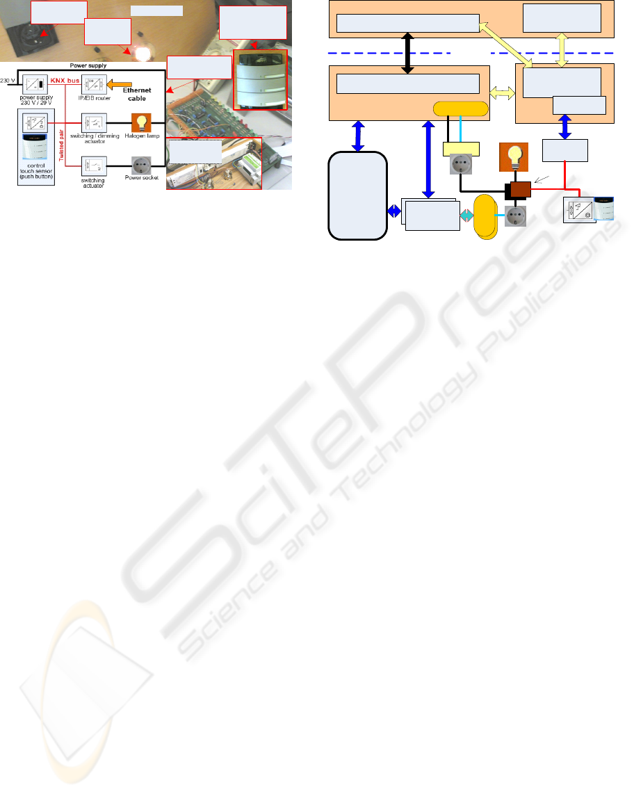
A simple domotic system bus was implemented as
illustrated in figure 2, which presents the set of KNX
devices used in our lab that, locally and remotely,
allows to: 1) turn on/off and adjust the brightness of
a halogen lamp; 2) switch on/off a power socket.
Besides the power supply required for the KNX bus,
this topology contains two device types: two actua-
tors (dimming and switching actuators) and a 3 gang
push button (control touch sensor). The actuators are
directly connected to the elements that will be re-
motely/locally controlled (the halogen lamp and the
power socket) using the push button. By using each
button of this sensor, users may locally turn on/off
the power socket, and the halogen lamp and control
its brightness. We connected the KNX bus to the
Web Server using an IP/EIB router. This router con-
verts all the IP frames, sent by the Web Server, to
EIB frames, to control and monitor each element.
All the devices available in the domotic system bus
were previously configured by a software named
ETS (ETS, 2007).
ADOPTING BUILDING AUTOMATION IN WEBLABS - Analysis of Requirements and Solutions
281
KNX/EIB
actuators
Weblab
Power
socket
Halogen
lamp
Control touch
sensor
(push button)
Schematic
connections
Figure 2: Schematic of the domotic connections and pic-
tures of the KNX domotic devices used in the weblab.
With ETS installed in a common PC with the Win-
dows XP OS, we: 1) defined an address for each
KNX device so they can be recognized in the bus; 2)
specified the operation of each device, configuring
its parameters (e.g. specified that a simple touch in
one button of the sensor will turn on/off the lamp);
and c) implemented a logic connection between the
devices to allow their communication. After config-
uring the bus and the devices, we had to download
that configuration to the system by connecting,
through a local network, the ETS to the KNX bus.
This transference required the use of the IP/EIB
router using a specific IP and the port 3671. For the
remote control, another software layer was specified
to control all KNX devices (as locally done through
the push button).
4.2 Remote Control
There are in the market some IP gateways that allow
controlling the KNX system through the Internet.
However, all have in common rigid Web interfaces,
which are not able to change, and they are expensive
(its price rounds 1000 €). If we use the required Web
Server to remotely control the KNX bus, the solution
will be cheaper and will facilitate the construction of
appropriated Web interfaces for each remote ex-
periment. Then, for the remote control, we devel-
oped a new software layer to control the lamp and
the power socket available in the weblab. Besides
controlling the KNX system, the implemented cli-
ent-server architecture is modular and may be used
by any experiment, since it works together with any
existing weblab. Figure 3 presents the software
modules implemented at our lab, where a particular
attention should be paid to the Web Server and to
the domotic bus connections.
Any experiment interface
Domotic system
interface
(JAVA Applet)
Remote Interface
Instrumentation
Server
Server application
Server application
(JAVA servlet)
Calimero API
Web
Server
IP / EIB
router
Experiment
Measurement
Instruments
Power
Supply
Measurement
Instrument
KNX
bus
Power Supply
RS 232
control
touch sensor
Halogen lamp
Power
Supply
UPS
Power socket
3
actuators
power line
I
n
t
r
a
n
e
t
Internet
Figure 3: Implemented software architecture to control the
KNX/EIB devices.
To control the experiment remotely, an HTTP server
installed in the Instrumentation Server may be re-
quired to enable users to download the experiment
interfaces (denoted by the black arrow). However,
since it is necessary a server application (installed in
the Web Server) together with a Web interface to
control the domotic bus, only one HTTP server, also
installed in the Web Server, is required to download
both interfaces. In this situation, both interfaces are
available from the Web Server and all communica-
tions between users and the lab are made through an
intranet (denoted by the yellow arrows). The appli-
cation developed to control the KNX domotic sys-
tem bus is required to be in the Web Server because
it controls the power socket of the UPS connected to
the Instrumentation Server, i.e. if the software appli-
cation was installed in the Instrumentation Server
the user would not be able to turn it on/off neither to
reset it. To avoid developing all the logic behind the
KNX/EIB protocol, we used the JAVA API Ca-
limero integrated in a JAVA server application
(Servlet). However, to use the Calimero API, an
IP/EIB router was required to transmit information
from the Servlet application to the KNX/EIB bus.
Since this application was developed using JAVA
software and as it follows a client-server architec-
ture, the Web Server runs an HTTP server named
TomCat (TomCat, 2007) to understand and process
user’s requests together with the Java Servlet Tech-
nology (Servlet, 2007). When a specific user wants
to access the lab, he/she makes an HTTP access to
the Web Server using a particular IP address, and a
Java Applet, illustrated in figure 4, will be
downloaded to his/her PC.
WEBIST 2008 - International Conference on Web Information Systems and Technologies
282
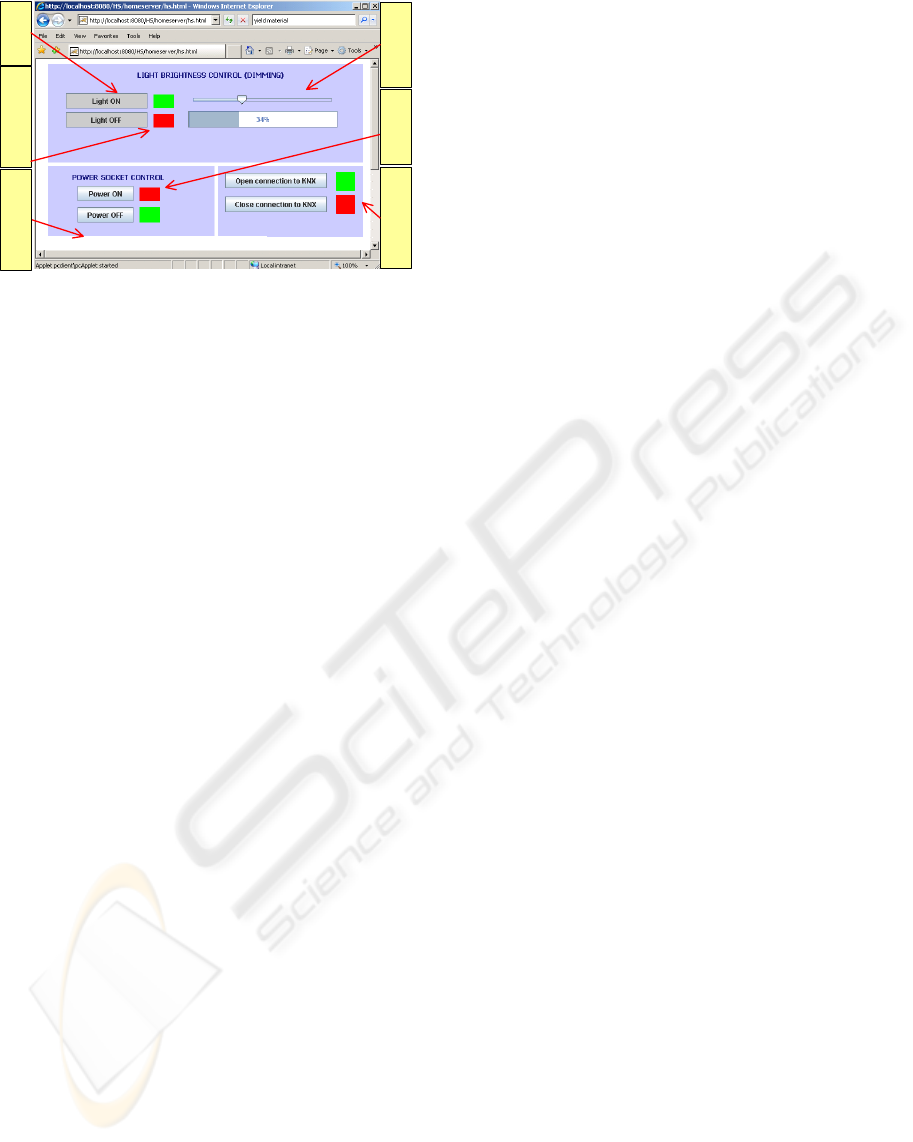
Light Intensity Status=34%
Turns on/off
the lamp
Indicates if the action
was made remotely
Controls the lamp
brightness
Open/close the KNX
bus connection
Turns on/off the
power socket
Information about
actions made in the bus
Figure 4: Web interface (Java Applet) used to control the
KNX domotic system bus.
To use this interface, an user must establish a con-
nection to the KNX/EIB bus, by pressing the buttons
available in bottom-right corner. After connected to
the bus, a message notifying the users will appear at
the bottom of the interface, indicating a successful
connection or any problem that may have occurred.
Assuming a successful connection, remote users are
able to control the KNX devices (lamp and power
socket) using the buttons to turn them on/off and the
slide bar to regulate the lamp brightness. Since we
adopted the HTTP as the communication protocol
between the Servlet application installed in the Web
Server and the Java Applet, any change made locally
may be actualized in the Applet by making a refresh.
This refresh procedure, which may be done by sim-
ple reloading the Applet, is made automatically
every 30 seconds, updating the interface for user’s
monitorization.
5 CONCLUSIONS
To provide a weblab it is necessary to implement a
hardware/software infrastructure. Usually, these
implementations do not follow a standard solution
(hardware and software) and the control of the
physical space together with the power sockets are
often forgotten. If these remote control facilities are
implemented in a weblab, the energy costs may be
reduced (the apparatus are able to be turned off
when not in use) and the quality of the experiments
may also increase, since all the physical space (light,
temperature, and others) may be controlled and
monitored. To provide all those facilities in a we-
blab, this paper proposed the use of the KNX domo-
tic bus to control through the Internet a halogen
lamp and a power socket using a JAVA Web inter-
face (an Applet). By developing specific Web inter-
faces, this same approach may be adapted to other
users’ devices, like PDAs, SmartPhones or Mobile
Phones, increasing the access versatility, by enabling
students/teachers to use recent mobile devices. To
conclude, this paper intended to be an alert to the
ability of controlling other aspects usually forgotten
in Remote Experimentation, namely the physical
environment and the power sockets used to supply a
weblab. Moreover, adopting the reliable and well
implemented KNX domotic system bus, will pro-
mote the construction of a uniform architecture us-
ing commercial devices.
ACKNOWLEDGEMENTS
This work was only possible with the collaboration
of Intelbus Lda. (Intelbus, 2007) that provided some
of the KNX devices used in the presented solution.
REFERENCES
B. Aktan, C. A. Bohus, L. A. Crowl and M. H. Shor, 1996.
Distance Learning Applied to Control Engineering
Laboratories. In IEEE Transactions on education,
vol.39, nº 3.
Jing Ma and Jeffrey Nickerson, 2006. Hands-on, Simu-
lated, and Remote Laboratories: A comparative Lit-
erature Review. In ACM Computing Surveys, vol. 38,
nº 3.
J. M. Ferreira and A. Cardoso, 2005. A Moodle extension
to book online labs. In International Journal of Online
Engineering (iJOE), vol. 1, nº. 2.
KNX, 2007. Association that promotes the KNX standard
for Home and Building Control. Available at:
www.konnex.org.
Calimero API, 2007. EIBnet/IP is a client library that
supports tunneling connections to the KNX/EIB bus.
Available at: calimero.sourceforge.net.
ETS, 2007. Tool Software design to configure intelligent
home and building control installations made with the
KNX system. Available at: www.konnex.org/knx-
tools/ets/intro.
TOMCAT, 2007. Apache Tomcat Web Server. Available
at: tomcat.apache.org.
Java Servlet Technology, 2007. Java Servlet technology
provides Web developers a consistent mechanism for
extending the functionality of a Web server and for ac-
cessing existing business systems. Available at:
java.sun.com/products/servlet.
Intelbus Lda., 2007. Company that implements solutions in
the domotic area. Available at: www.intelbus.pt.
ADOPTING BUILDING AUTOMATION IN WEBLABS - Analysis of Requirements and Solutions
283
