
A PROCESS-DRIVEN METHODOLOGY FOR CONTINUOUS
INFORMATION SYSTEMS MODELING
Alfredo Cuzzocrea
1,2
, Andrea Gualtieri
2
and Domenico Saccà
1,2
1
ICAR Institute and
2
DEIS Department, University of Calabria, Italy
Keywords: Information Systems Methodologies; Information Systems Specification; Process-Driven Methodologies for
Designing Information Systems; Information Systems Engineering.
Abstract: In this paper, we present a process-driven methodology for continuous information systems modeling. Our
approach supports the whole information system life-cycle, from planning to implementation, and from
usage to re-engineering. The methodology includes two different phases. First, we produce a scenario
analysis adopting a Process-to-Function approach in order to capture interactions among components of
organization, information and processes. Then, we produce a requirement analysis adopting a Function-for-
Process and package-oriented approach. Finally, we deduce an ex-post scenario analysis by applying
process mining techniques on repositories of process execution traces. The whole methodology is supported
by UML diagrams organized in a Business Model, a Conceptual Model, and an Implementation Model.
1 INTRODUCTION
As information systems become complex, the need
for a highly-structured and flexible methodology
becomes mandatory, since traditional approaches
(Center for Technology in Government, University
at Albany, 2003) result to be ineffective when
applied to non-conventional cases such as the
modeling of advanced inter-organizational scenarios.
Several information systems modeling techniques
have been proposed during the last decades in order
to cope with complex information systems. A
complete survey can be found in (Giaglis, 2001).
Among the most interesting classes of solutions,
methodologies oriented to processes, which play a
critical role in any organization, introduce several
features that perfectly marry the complexity and the
difficulty of next-generation information systems.
Inspired by these considerations, in this paper we
propose an innovative process-driven methodology
for continuous information systems modeling, which
encompasses a number of aspects of the information
system life-cycle, from planning to implementation,
and from usage to re-engineering.
Our methodology basically founds on software
planning and development methodologies, and it can
be considered as a reasonable alternative to
traditional proposals based on the Waterfall Model
(Royce, 1970). Similarly to lightweight and agile
software development patterns (Cockburn, 2002),
this methodology adopts iterative procedures, and it
is characterized by short recurrent steps that are
target-oriented and suitable to support an adaptive
evolution of the whole information system modeling
phase. In more detail, in our methodology software
planning and development are modeled via
specifying two macro-phases, directly connected to
the concepts of process and function. In the first
phase, we produce a scenario analysis adopting a
Process-to-Function (P2F) approach, where we
capture interactions among components of
organization, information and processes. In the
second phase, we produce a requirement analysis
adopting a Function-for-Process (F4P) approach,
where the development of the information system is
modeled, planned and dynamically reported
according to a package-oriented organization. These
phases are implemented by UML diagrams (Booch
et al., 2005) organized in a Business Model, a
Conceptual Model, and an Implementation Model.
After the implementation and enactment of the
information system, logs of executions are stored
and analyzed by process mining techniques (e.g.,
(Greco et al., 2005)), which aim at extracting useful
knowledge from traces generated by processes of at-
work information systems. This way, we can
produce an ex-post analysis of scenarios, thus
highlighting similarities and differences due to
82
Cuzzocrea A., Gualtieri A. and Saccà D. (2008).
A PROCESS-DRIVEN METHODOLOGY FOR CONTINUOUS INFORMATION SYSTEMS MODELING.
In Proceedings of the Tenth International Conference on Enterprise Information Systems - ISAS, pages 82-88
DOI: 10.5220/0001677100820088
Copyright
c
SciTePress

diverse execution scenarios of the target information
system.
2 RELATED WORK
The strict relationship among business processes and
information systems has been firstly recognized in
(Davenport & Short, 1990) at early 90’s. Business
processes heavily influence final structure and
functionalities of information systems.
Symmetrically, the development of the information
system influences the design of specific business
processes of the target organization.
According to this evidence, several information
systems modeling methodologies that, like ours, are
focused on processes have appeared in literature
recently. Also, some interesting applications of this
novel class of methodologies have been proposed.
Among such applications, we recall: (i) integration
of process-oriented techniques and Data Warehouses
(zur Muehlen, 2001), (ii) simulation of business
processes to precisely capture information systems
requirements (Serrano, 2003), (iii) process-driven
modeling in the context of e-learning systems (Kim
et al., 2005).
From the straightforward convergence of the
mentioned research efforts and practical
applications, it is reasonable to claim that achieving
a total synergy between the design of business
processes and the development of information
systems should be the goal of any organization, as
stated in (Grover et al. 1994; van Meel et al., 1994;
Tuefel & Tuefel, 1995). Nevertheless, in real-life
organizations business analysts and information
systems engineers very often have distinct roles
within the organization, and, in addition to this, very
often they use different tools, techniques and
terminologies (Earl, 1994). This contributes to make
the achievement of the above-introduced synergy
more difficult, and poses severe drawbacks with
respect to a complete integration between
organizations and information systems.
(Giaglis, 2001) proposes an accurate taxonomy
of business processes and information systems
modeling techniques, also putting in evidence
similarities and differences among the available
alternatives. In (Giaglis, 2001), according to (Curtis
et al., 1992), the following perspectives of an
information systems modeling technique are
systematized: (i) functional perspectives, (ii)
behavioral perspectives, (iii) organizational
perspectives, and (iv) informational perspectives. As
we demonstrate throughout the paper, our proposed
methodology strictly follows this paradigm, and
meaningfully includes all the introduced
perspectives, plus innovative amenities.
Implementation-wise, the methodology we
propose is based on three levels of modeling and
analysis, enriched with a final ex-post analysis of
business process traces. Each level founds on
classical UML diagrams enriched with stereotypes
aiming at carefully modeling even-complex business
processes by means of the so-called UML Profiles.
The above-described constitutes a consolidate
methodology for information systems modeling
techniques. For instance, in (Vasconcelos et al.,
2001) a UML-based framework for modeling
strategies, business processes and information
systems of a given organization is proposed.
Similarly to ours, this framework adopts a multi-
level approach during the modeling phase. Other
proposals based on the usage of specialized UML
profiles for capturing several aspects of modeling
information systems are (Castela et al., 2001; Neves
et al., 2001; Sinogas et al., 2001).
Ex-post analysis of business process traces can
be instead regarded as an innovative aspect of the
methodology we propose. This resembles the work
of Mendes et al. (2003), where scenario evolution is
modeled in terms of a specific process that captures
organizational changes. Contrary to this, in our
methodology scenario evolution is not captured on
the basis of a fixed, a-priori pattern, but instead it is
deduced from the analysis of process traces
originated by the interaction between users and the
system.
Another distinctive feature of our methodology is
represented by the idea of separately modeling the
static knowledge (i.e., the knowledge modeled by
means of Use Case and Class Diagrams) and the
dynamic knowledge (i.e., the knowledge modeled by
means of Activity Diagrams). This amenity if finally
combined with the ex-post analysis illustrated above,
thus allowing us to achieve a powerful tool for
mining and reasoning on processes, and,
consequentially, significantly improving the
modeling capabilities of the methodology we
propose.
3 SCENARIO ANALYSIS
AND THE BUSINESS MODEL
Selection and definition of business processes that
characterize the scenario in which the information
system will operate are milestones of the planning
A PROCESS-DRIVEN METHODOLOGY FOR CONTINUOUS INFORMATION SYSTEMS MODELING
83
phase. These components are realized within the
Business Model, which is thus an essential input to
the subsequent selection and definition of functions
able to manage information useful for the specific
context in which the information system will
operate.
Scenario analysis is obtained as a combined
result of the study of the target organization,
interviews to members of the organization, reading
of documents, selection of relevant procedures etc.
All these elements are referred and represented in
the Business Model, which is defined as a
formalization of organization processes, actors of
the organization, and information. To efficiently
support this formalization, Business Model is
organized in several components: (i) Process
Schema, which models processes of the information
system; (ii) Actor Schema, which models actors of
the information system; (iii) Archive Schema, which
models archives of the information system. All these
schemas are modeled as UML Use Case Diagrams.
Actors and archives are formalizations of active
and passive entities that interact with processes. We
represent them via adopting stereotypes built on the
native UML actor element. We consider as actors all
the operators (human or automatic) that activate or
enact a process of the organization. An archive is
instead every information source useful for the
execution of a process. In Actor and Archive
Schemas, we model and represent taxonomies and
ontologies (Fensel, 2001) of entities, also in a
hierarchical fashion, in order to permit a meaningful
contextualization of organization and information
elements.
In the Process Schema, processes are modeled by
means of a top-down approach. Specifically, we first
analyze and model processes, and then select sub-
processes that characterize each of them.
Implementation-wise, hierarchies of processes are
obtained by means of packages.
Distinguishing between processes and sub-
processes is a non-trivial engagement, which also
strongly depends on the particular application
context. In our methodology, in order to cope with
this conceptual dichotomy we assert what follows. A
process P is a set of procedures that are finalized to
obtain a goal, starting from the input. A process
involves a number of actors, and requires
information modeled in terms of archives. Finally, a
process is composed by sub-processes. A sub-
process P
i
is an element of a process P, more
restricted than P, but having the same formalization.
A sub-process models components required for the
release of a sub-service (or sub-product) of the
information system. These components are referred
as the path of execution of the sub-process. Finally, a
sub-process can be structured, i.e. composed itself
by other sub-processes in a hierarchical fashion, or
atomic, i.e. without any sub-sub-process (in this
case, the sub-process is named as activity).
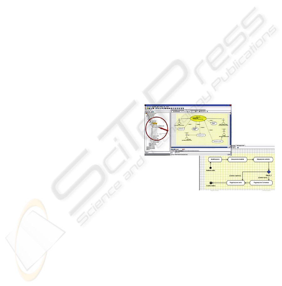
An activity is an atomic element that represents a
specific portion of work, and constitutes a logic step
within a process. To model evolution of activities
within a same process P, we make use of an Activity
Diagram (see Figure 1) that establishes the temporal
order of the activities during the enactment of P.
Top-down analysis focuses on high-level
processes characterizing the information system
scenario. In the visual representation implementing
such analysis, we introduce a package for every
macro-process. Given a macro-process P, the
package contains a Use Case Diagram in which the
use-case element corresponding to P is connected
with use-case elements corresponding to every sub-
process P
i
of P. To model these connections, we use
the UML constructs include, extend and specialize.
In more detail, for these constructs we assume the
following semantics.
Figure 1: From a Use Case Diagram to the related Activity
Diagram.
A process P “includes” a sub-process P
i
if, in
every instance of P, an instance of P
i
is required to
be executed. A sub-process P
i
“extends” a process P
if, in every instance of P, an instance of P
i
is
executed only if a given condition is verified (this
condition is expressed by the so-called extension
point element). A sub-process P
i
“specializes” a
process P if P
i
involves all the sub-processes
involved by P, plus other specific activities.
UML associations are used to connect a use-case
representing a process P or a sub-process P
i
to an
actor A or an archive S. Therefore, we are able to
express that an actor A executes/interacts-with a
process P (or a sub-process P
i
), and that a process P
ICEIS 2008 - International Conference on Enterprise Information Systems
84
(or a sub-process P
i
) requires or modifies
information contained in an archive S during its
execution.
For each process P, we then model the path of
execution of its sub-processes, via associating an
Activity Diagram to P (see Figure 1). As a
consequence, we finally obtain that in the Use Case
Diagram of P we represent a first analysis about the
composition of P, and in the Activity Diagram we
formalize the sequence of execution of activities of
P and express pre-conditions and post-conditions
among activities via conventional UML constructs
join, fork and merge.
This decomposition is replicated for every sub-
process that is itself a structured (sub-)process. To
this end, we select the sub-sub-processes of this sub-
process and connect them to it by means of
constructs include, extend or specialize. Then, we
model the dynamic of the evolution of the sub-
process via linking it to a specific Activity Diagram.
In total, for each process P, we introduce an
Activity Diagram containing sub-processes P
i
directly connected to P. Furthermore, if a sub-
process P
i
itself involves sub-sub-processes P
i,j
, their
sequences of execution should be represented by
another Activity Diagram connected to P
i
.
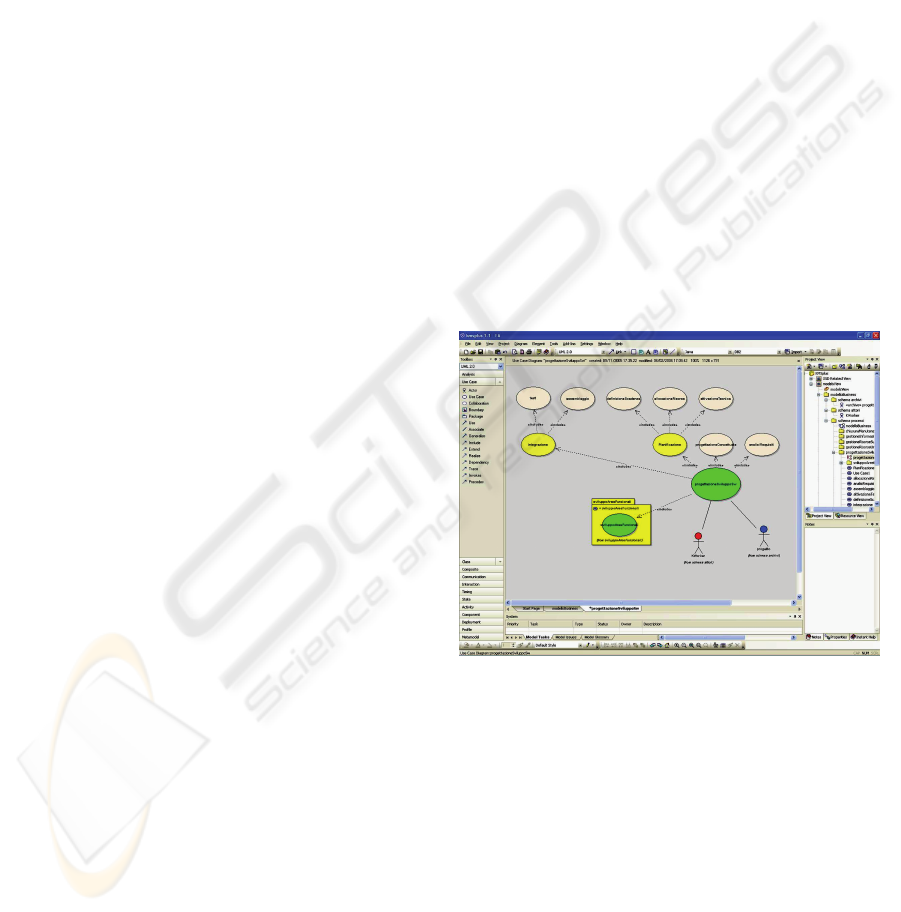
Finally, in our methodology the hierarchical
nature of modeling processes is handled as follows.
If a sub-process P
i
of a process P is too much
articulated to be represented in the main Use Case
Diagram (of P), we introduce a sub-package B
i
that
contains another Use Case Diagram (of P
i
). This
allows us to obtain a modular and incremental
process organization that gives us benefits at both
the modeling and visualization tasks. In the main
Use Case Diagram, we represent the sub-package B
i
and its related sub-process P
i
, and we connect B
i
to
P. As said, the result is a hierarchical and modular
representation of processes (see Figure 2) that can be
easily modified in a specific portion without
conditioning the whole structure of the model.
4 ANALYSIS OF FUNCTIONS
AND THE CONCEPTUAL
MODEL
Scenario analysis describes the context in which the
information system will operate. The next step is to
analyze and model functions supported by the
system in order to facilitate the execution of
processes within the organization. Conceptual
Model is the output of this phase. In the Conceptual
Model, we provide: (i) a formal schema of functions
and users, (ii) a formal schema of data, (iii) a formal
schema of interactions between functions and data.
Furthermore, Conceptual Model also represents
functional blocks and views on data (i.e., schemas of
information sources). Functional blocks are modeled
by use-case packages and taxonomies of actors,
according to an approach similar to the one used to
model processes in the Business Model (see Section
2). Data views are instead represented by means of
Class Diagrams. Therefore, we can state that
Conceptual Model is characterized by two aspects
that capture the overall knowledge of the
information system: (i) static analysis given by the
Data Schema, which describes schemas of
information sources, and View Schema, which
describes views on the latter schemas; (ii) dynamic
analysis given by the User Schema, which models
users, and Function Schema, which models
functions. Both static and dynamic analysis concur
to capture even complex aspects of the information
system, thus adding novel and useful amenities to
traditional information systems design
methodologies.
Figure 2: Modular representation of processes.
Data Schema contains a Class Diagram that
represents a conceptual model of the database
underlying the information system. We use
database-engineering-oriented UML stereotypes
such as <<Table>> and <<Key>> in order to adapt
UML classes and attributes to the goal of
representing database entities, thus modeling a data
schema. Foreign keys and cardinality constraints are
instead represented via UML associations among
classes. At this level, we make use of composition
and aggregation associations, and taxonomies (e.g.,
generalization) to represent logical relations among
database entities. Therefore, Data Schema is a high-
A PROCESS-DRIVEN METHODOLOGY FOR CONTINUOUS INFORMATION SYSTEMS MODELING
85
level description of the database underlying the
target information system.
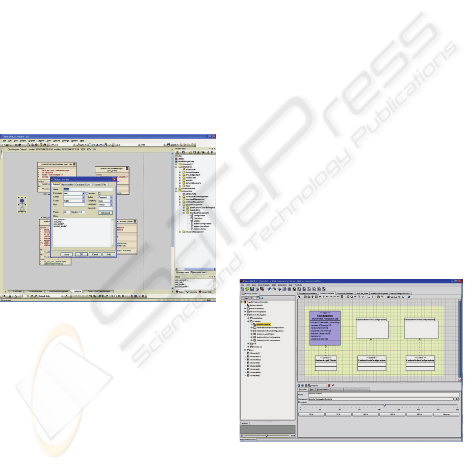
View Schema contains a Class Diagram named
as View Catalogue. A view is a portion of database
useful in a specific functional context. Each view is
represented by a package containing a Class
Diagram in which the involved-by-the-view entities
of the database are shown, along with their relations.
In each package, a view is represented by means of
the UML stereotype <<View>>, and can be exported
in the Function Schema to model in more detail the
interaction among functions and data they require or
modify. Also, we associate a documentation to each
view V (see Figure 3), such that this documentation
contains additional information on V like: (i) the
logical name of V; (ii) for each entity, the list of
specific attributes – obtained as a selection of the
whole set of attributes – that are useful in the
specific functional context; (iii) the way used in the
specific context to navigate associations among
entities etc.
Figure 3: A View and its documentation.
User Schema has the same syntax of the one
relative to the Actor Schema in the Business Model
(see Section 2). While actors are entities (human or
automatic) that activate or enact processes of the
organization (including processes that are not
codified as functionalities of the information
system), users are instead entities (human or
automatic) that properly interact with the
information system in the real-life realization.
Similarly to users, functions in the Function
Schema are modeled by adopting syntax analogous
to the one employed in the Business Model to
represent processes, with the difference that rather
than archives (i.e., generic information sources of
the organization) here we model views involved by
functionalities of the information system, being such
views coming from the View Schema.
5 DEVELOPMENT OF THE
INFORMATION SYSTEM
AND THE IMPLEMENTATION
MODEL
Once requirement analysis is completed and
Conceptual Model is defined, a physical planning of
the information system is necessary. Conceptual
schemas defined in the Conceptual Model are
mapped on the software architecture of the system.
On the basis of the specific information system,
different architectural solutions can be chosen, but
every choice should include at least three tiers: (i) a
Database Level to model information/data sources
of the system; (ii) a Control Level to models
(software) classes implementing the application
logic of system procedures; (iii) an Interface Level
to model forms handling the interaction between
users (human or automatic) and the system.
In order to efficiently support these
requirements, the Implementation Model is
constituted by several components: (i) Architecture,
which contains a representation of physical elements
of the information system (i.e., the software
architecture of the system); (ii) Database, which
implements the Database Level; (iii) Control, which
implements the Control Level; (iv) Interface, which
implements the Interface Level.
Figure 4: A Control Schema.
Similarly to other models of our methodology,
each component is implemented by a package,
according to the following organization.
Architecture component contains a Deployment
ICEIS 2008 - International Conference on Enterprise Information Systems
86
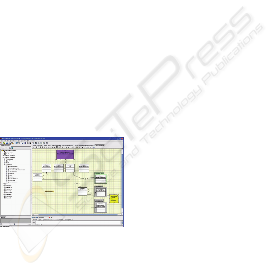
Diagram where nodes and components of the system
implementation are defined. Furthermore, just like
other constructs of our methodology, it is possible to
define sub-packages in order to obtain a modular
representation. Database component contains a Class
Diagram enriched by stereotypes, named as DB
Schema, which allows us to represent the schema of
data stored in the information/data sources of the
system (i.e., the database underlying the system).
With respect to the Data Schema of the Conceptual
Model, in the DB Schema of the Implementation
Model we model in detail all components of data
tables (e.g., attributes with data type, attribute
domains and checks etc), in a similar way to what
happens in conventional CAD tools for E/R
diagrams, thus obtaining a linear description of the
database underlying the system. Control component
contains a Class Diagram, named as Control Schema
(see Figure 4), in which a catalogue of control
classes is represented. Each control class is
implemented as a UML class with stereotype
<<Control>>, and contains methods used by the
Interface Level to manage data from the Database
Level. Also, each control class refers to one or more
views inherited from the DB Schema on the basis of
their relevance and scope with respect to the specific
functional context. Methods of each control class are
described within the UML class in forms of software
interfaces (e.g., Java-based) and documentation in
free text.
Figure 5: An Interface Schema.
Following the organization of the
Implementation Model, Control Level is invoked by
the Interface Level containing a Class Diagram,
named as Interface Schema (see Figure 5), which
models the interaction between users and the system.
Recall that paths of executions are modeled by
Activity Diagrams of the Conceptual Model. Based
on these paths, in the Implementation Model we
model a sequence of forms, which are UML classes
enriched by specific stereotypes. Specifically, a form
is characterized by three elements that determine the
final representation of such form: (i) entry unit,
which is an area of the form where users submit
input elements to the system via traditional GUI
controls such as text fields, combo boxes, check
boxes etc; (ii) data unit, which is an area of the form
where information derived from the underlying
database (i.e., sets of tuples) is shown; (iii) display
unit, which is an area of the form where static
components are shown (e.g., help textual
information describing how to use form controls).
In our methodology, a form can be a plain form,
a list form, or a recursive form. Plain forms are basic
realizations of the construct form. List forms,
modeled by the UML stereotype <<FormL>>, are
used to represent forms in which sets of tuples are
shown. Recursive forms, modeled by the UML
stereotype <<Form*>>, are used to represent forms
that are shown many times, one for each tuple
corresponding to a specific parameter.
When forms transmitting parameters to other
forms are considered (e.g., during user transactions),
we support this facet of the information system via
appending specific attributes to UML association
constructs. These attributes are described by the
UML stereotype <<LinkP>>. To ensure data
consistency, we simply impose that the type of
transmitted parameters is the same of (appended)
attributes in the related UML class. Finally,
conventional structural links, i.e. links without
embedded parameters, are modeled by the UML
stereotype <<Link>>. It should be noted that this so-
large availability of different UML constructs
provided by our methodology allows us to model
even complex front-ends for process- and data-
intensive information systems.
6 CONCLUDING REMARKS
AND FUTURE WORK
A complete methodology for continuous information
systems modeling has been presented in this paper.
This methodology makes use of several UML-based
diagrams, models and constructs that found on
processes and other entities such as actors, archives,
and functions. These components are able to capture
even complex features of advanced information
systems. The proposed methodology is actually
experimented in Exeura (Exeura, 2008), a spin-off
company of the University of Calabria that operates
A PROCESS-DRIVEN METHODOLOGY FOR CONTINUOUS INFORMATION SYSTEMS MODELING
87

in the Information Technology (IT) and Knowledge
Management (KM) areas. This experience confirms
us that the proposed methodology results to be
particularly suitable to application scenarios whose
information systems modeling requires high
flexibility and high scalability.
Future work is oriented towards encapsulating
within the proposed methodology innovative aspects
such as the automatic generation of wrappers classes
for distributed and heterogeneous information
sources, and the automatic generation of source code
starting from signatures of control classes.
REFERENCES
Booch, G., Rumbaugh, J., and Jacobson I., 2005. The
Unified Modeling Language User Guide, 2
nd
ed.,
Addison-Wesley, Reading, MS, USA.
Castela, N., Tribolet, J.M., Silva, A., and Guerra, A.,
2001. Business Process Modeling with UML. In Proc.
of the 3
rd
ICEIS Int. Conf., Vol. 2, pp. 679-685.
Center for Technology in Government, University at
Albany, 2003. A Survey of System Development
Process Models, TR CTG.MFA – 003, available at
http://demo.ctg.albany.edu/publications/reports/survey
_of_sysdev/survey_of_sysdev.pdf
Cockburn, A., 2002. Agile Software Development,
Addison-Wesley, Reading, MS, USA.
Curtis, W., Kellner, M.I., and Over, J., 1992. Process
Modeling. In Communications of the ACM, Vol. 35,
No. 9, pp. 75-90.
Davenport, T.H., and Short, J.E., 1990. The New
Industrial Engineering: Information Technology and
Business Process Redesign. In Sloan Management
Review, Vol. 31, No. 4, pp. 11-27.
Earl, M.J., 1994. The New and the Old of Business
Process Redesign. In Journal of Strategic Information
Systems, Vol. 3, No. 1, pp. 5-22.
Exeura – Knowledge Management Solutions,
http://www.exeura.it
Fensel, D., 2001. Ontologies: A Silver Bullet for
Knowledge Management and Electronic Commerce,
Springer Verlag, Berlin, GE.
Giaglis, G.M., 2001. A Taxonomy of Business Process
Modeling and Information Systems Modeling
Techniques. In International Journal of Flexible
Manufacturing Systems, Vol. 13, No. 2, pp. 209-228.
Greco, G., Guzzo, A., Manco, G., and Saccà, D., 2005.
Mining and Reasoning on Workflows. In IEEE
Transactions on Knowledge and Data Engineering,
Vol. 17, No. 4, pp. 519-534.
Grover, V., Fielder, K.D., and Teng, J.T.C., 1994.
Exploring the Success of Information Technology
Enabled Business Process Reengineering. In IEEE
Transactions on Engineering Management, Vol. 41,
No. 3, pp. 276-284.
Kim, K-H, Yoo, H.-J., and Kim, H.-S., 2005. A Process-
Driven E-Learning Content Organization Model. In
Proc. of 4
th
IEEE ACIS Int. Conf., pp. 328-333.
van Meel, J.W., Bots, P.W.G., and Sol, H.G., 1994.
Towards a Research Framework for Business
Engineering. In IFIP Transactions A: Computer
Science and Technology, Vol. 54, pp. 581-592.
Mendes, R., Mateus, J., Silva, E., and Tribolet, J.M., 2003.
Applying Business Process Modeling to
Organizational Change. In Proc. of the 2003 AMCIS
Int. Conf.
zur Muehlen, M., 2001. Process-Driven Management
Information Systems - Combining Data Warehouses
and Workflow Technology. In Proc. of the 4
th
ICECR-
4 Int. Conf., pp. 550-566.
Neves, J., Vasconcelos, A., Caetano, A., Sinogas, P.,
Mendes, R., and Tribolet, J.M., 2001. Unified
Resource Modelling: Integrating Knowledge into
Business Processes. In Proc. of the 3
rd
ICEIS Int.
Conf., Vol. 2, pp. 898-904.
Royce, W.W., 1970. Managing the Development of Large
Software Systems. In Proc. of the 1970 IEEE
WESCON Int. Conf., pp. 1-9.
Serrano, A. 2003. Capturing Information System’s
Requirement Using Business Process Simulation. In
Proc. of the 15
th
ESS Int. Conf.
Sinogas, P., Vasconcelos, A., Caetano, A., Neves, J.,
Mendes, R., and Tribolet, J.M., 2001. Business
Processes Extensions to UML Profile for Business
Modeling. In Proc. of the 3
rd
ICEIS Int. Conf., Vol. 2,
pp. 673-678.
Teufel, S., and Teufel, B., 1995. Bridging Information
Technology and Business: Some Modeling Aspects. In
SIGOIS Bulletin, Vol. 16, No. 1, pp. 13-17.
Vasconcelos, A., Caetano, A., Neves, J., Sinogas, P.,
Mendes, R., and Tribolet, J.M., 2001. A Framework
for Modeling Strategy, Business Processes and
Information Systems. In Proc. of the 5
th
IEEE EDOC
Int. Conf., pp. 69-80.
ICEIS 2008 - International Conference on Enterprise Information Systems
88
