
INTRODUCING SERVICE-ORIENTATION INTO
SYSTEM ANALYSIS AND DESIGN
Prima Gustiene and Remigijus Gustas
Department of Information Systems, Karlstad University, 651 88 Karlstad, Sweden
Keywords: Service-oriented analysis and design, enterprise modelling, integrity of static and dynamic aspects.
Abstract: The conventional methods of information system analysis and design are not based on service-oriented
paradigm that facilitates control of business process continuity and integrity. Service-oriented
representations are more comprehensible for business experts as well as system designers. It is reasonable to
conceptualize a business process in terms of service-oriented events, before the supporting technical system
is designed. UML design primitives abstract from the concrete implementation artefacts and therefore they
are difficult to comprehend for business analysis experts. The presented approach for service-oriented
analysis is based just on three types of events: creation, reclassification and termination, which can also be
used for the semantic integrity and consistency control. In this paper, the basic service-oriented constructs
are defined. Semantics of these implementation neutral artefacts are analysed in terms of their associated
counterparts that are used in object-oriented design.
1 INTRODUCTION
Service-oriented system analysis and design is a new
emerging approach that has evolved from object-
oriented (Blaha & Rumbaugh, 2005) and compo-
nent-based software engineering (Szyperski, 1998).
Experience from Service-Oriented Architecture
(SOA) implementation projects (Zimmerman et al.,
2004) suggests that traditional information system
modelling methods cover just part of required mo-
delling notations that are currently emerging under
the service-oriented analysis and design (SOAD)
approaches. There are many attempts of solving this
problem by defining new notations such as
Archimate (Lankhorst et al., 2005), where the expli-
cit concept of service is introduced, but still the
constructs for structural modelling of business data
are underdeveloped. The lack of research on seman-
tic integrity (Kim et. al., 2000), (Harel & Rumpe,
2004), among different types of diagrams is not a
new fact. The consequence of analysing static and
dynamic aspects in isolation results that additional
quality assurance procedures are necessary for the
semantic consistency and integrity control across
various dimensions (Zachman, 1996).
The object-oriented methods are typically based
on modelling of the use case, logical data, process,
implementation and deployment views (Booch et al.,
1999). Principles of integration and principles of
concern separation are not clear in the conventional
system analysis and design methodologies. As the
concept of service is rather well understood in
different domains, it could be successfully used for
breaking down system functionality into coherent
non overlapping subsystems. Some information
system development methodologies have argued for
a single meta-model (Dori, 2002), (Gustas &
Gustiene, 2004) that integrates different perspectives
(Zachman, 1996). Traceability from one diagram
type to another becomes difficult if dispersed views
and perspectives are defined in isolation. A funda-
mental problem resides in a difficulty to integrate
the static and behavioural aspects of information
system specifications. Most of the conventional
system analysis and design methodologies, including
object-oriented methods, abstract from concrete
implementation artefacts, which are more compre-
hensible for software designers, but not for non-
technicians, who play a key role as semantic system
integrators. It is recognised that UML support for
such task is quite vague.
SOA (Erl, 2005) represents a set of design
principles (Krafzig et al., 2005) that enable business
processes to be analysed in terms of services. The
most fascinating idea about service concept is that it
can be applied equally well to the organizational as
well as software components, which can be viewed
as service requestors and service providers. Service
propositions, requests and service provision within a
value chain or within business process can be
189
Gustiene P. and Gustas R. (2008).
INTRODUCING SERVICE-ORIENTATION INTO SYSTEM ANALYSIS AND DESIGN.
In Proceedings of the Tenth International Conference on Enterprise Information Systems - ISAS, pages 189-194
DOI: 10.5220/0001688301890194
Copyright
c
SciTePress
defined by using pragmatic patterns (Moor, 2005) in
terms of communication actions (Dietz, 2001).
Service semantics cannot be described indepen-
dently of how these self-contained business and
technical components are externally used (Moor,
2005). Integration of internal and external behaviour
(Lankhorst et al., 2005) creates big challenges for
the object-oriented modelling as well as business
process modelling approaches. Since the perspec-
tives are highly intertwined, it is critical to maintain
interdependency relations across multiple diagrams.
Integration of internal and external behaviour,
which is encapsulated in a service concept, provides
modelling flexibility. Business processes can be
changed by replacing or recomposing services. Con-
ceptual representations of service architectures can
be used for specification of business processes in
terms of organisational and technical services. Servi-
ces can be understood as organizational and techni-
cal system components, which can be used by
various actors to achieve their goals. Enterprise
system can be defined as a set of interacting loosely
coupled components, which are able to perform the
specific services on request. The objective of this
study is to define the basic constructs that can be
used for service-oriented analysis and semantic
integration of different modelling dimensions. This
paper is organised as follows. The next section,
defines a set of the basic constructs for service-
oriented analysis. The bridging from conceptual
representation of service architecture to component
based representation is given in the third section.
The fourth section presents the bridging from
service-oriented to object-oriented diagrams. The
conclusion section outlines the perspective of
service-orientation.
2 BASIC SERVICE-ORIENTED
CONSTRUCTS
Service-oriented analysis and design is a hot
research topic (Gottschalk et al., 2002). Many
approaches are focusing on design of services from
software components using object-oriented methods
(Gustas & Jakobsson, 2004), but such design of
service is not directly applicable for conceptual
modelling of services. There are just two basic
events in our service-oriented approach: creation and
termination (Gustas & Gustiene, 2007). They are
fundamental for the definition of reclassification
event that can be understood as a communication
action (Dietz, 2001). A communication action
between two actors (agent and recipient) indicates
that one actor depends on another actor. An instance
of actor can be an individual, a group of people, an
organisation, a machine, a software or hardware
component, etc. The actor dependency (
) is
usually viewed as a physical, information or a
decision flow between two parties involved.
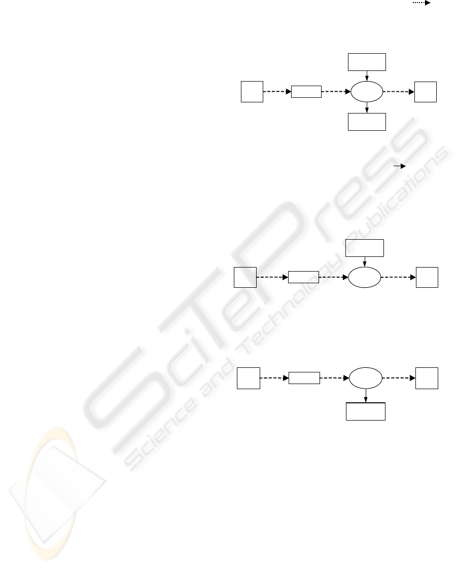
Graphical notation of the reclassification event is
presented in figure 1.
Figure 1: Construct for representation of reclassification.
An action is defined as a transition ( ) from the
precondition object class to the postcondition object
class. Fundamentally, two kinds of changes occur
during any transition: removal of an object from a
precondition class and creation of an object in a
postcondition class. The termination event is
represented in figure 2.
Figure 2: Construct for representation of termination.
Removal action terminates all the associations of
an object. The creation action must bring all its asso-
ciations of an object into existence. Graphical nota-
tion of the creation event is represented in figure 3.
Figure 3: Construct for representation of creation.
A similar type of actor link that is called the
strategic dependency was introduced in i* frame-
work for early-phase requirement engineering (Yu &
Mylopoulos, 1994). In our approach, the strategic
dependency is considered at the same time to be an
action and a communication flow. An agent initiates
a flow by using an action to achieve his goal. The
effect of any action is a reclassification, removal or
creation of an object. Composition of these three
types of basic constructs is used for concep-
tualisation of a continuous or finite lifecycle for one
or more objects in a service interaction loop.
In this paper, the semantics of various kinds of
static associations are defined by cardinality
constraints without names of mappings in two
Agent
Reci-
pient
Flow Action
Pre-condition
Object Class
Post-condition
Object Class
Agent
Reci-
pient
Flow
Removal
Action
Object Class
Agent
Reci-
pient
Flow
Creation
Action
Object Class
ICEIS 2008 - International Conference on Enterprise Information Systems
190
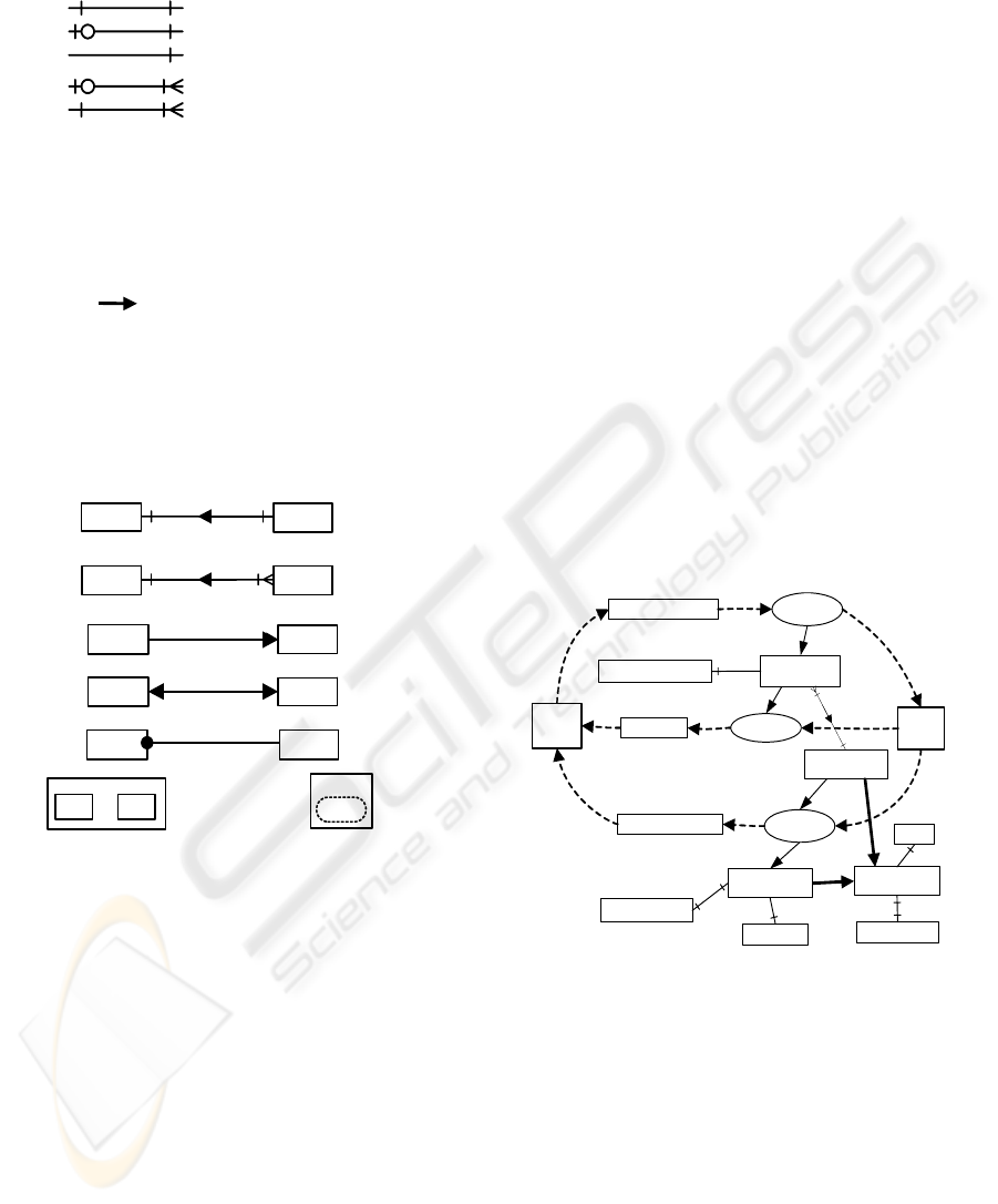
opposite directions. Graphical notation of static
associations is presented in figure 4.
Figure 4: Graphical notation of associations.
Generalization relationship facilitates incremental
specification and exploitation of common properties
between classes (Maciaszek, 2005). In such a way,
associations can be inherited by several concepts.
Inheritance (
) is often promoted as a core link to
connect a specific concept to more general one.
Composition is a conceptual dependency used to
relate a whole to other concepts that are viewed as
parts. The composition dependency is more restric-
tive than the aggregation dependency. Graphical no-
tation of the other types of the basic static depen-
dencies is presented in figure 5.
Figure 5: Graphical notation of the static dependencies.
Static dependencies define complementary details
for compositions of the basic event constructs,
which are very important to understand semantics of
service architectures.
3 FROM CONCEPTUAL
REPRESENTATION OF
SERVICES TO COMPONENTS
Many services can be implemented as software
components and therefore, they should be also
specified on a computation specific layer but they
should be first conceptualised on the computation
independent level of abstraction. Every commu-
nication action represents creation, termination or
reclassification of one or more objects. Static depen-
dencies predefine which object links must be created
by a communication action. It should be noted that
the creation and termination actions are propagated
along the composition hierarchy links. Basic events
of service architecture are computation neutral
constructs, which help system designers to concep-
tualise software components at the computation
specific level of abstraction.
Conceptual representation of service architecture
is defined by using one or more interaction loops.
Semantics of one loop can be defined by using any
two basic constructs. Superimposition of two inte-
raction loops may result into sequence, branching or
synchronisation of actions (Gustas & Gustiene,
2007). By matching the actor dependencies from
agents to recipients, one can explore opportunities
that are available to the actors. We shall illustrate
interplay of three basic constructs by one interaction
loop of an exclusive choice pattern (BPMN Working
group, 2004). Interaction loop between two actors
(Person and a chief executive (CEO) of a company)
is composed of a sequence of creation, termination
and reclassification events, which are illustrated in
figure 6.
Figure 6: Illustration of three basic constructs.
A person has a possibility to apply for
employment by sending an application to CEO of a
company. If CEO receives the application, then an
object of Application and an associated object of
Applicant are created (see composition link).
According to the semantics of basic constructs, CEO
is obliged either to employ an applicant or to reject
an application. Please note that both actions
predefine removal of an application object. If CEO
decides to reject application, then an applicant is
terminated. Otherwise, an Applicant object is
reclassified to employee by Employ action, which is
exclusive to Reject action. Please note that an
B and C are exclusive
specialisations of A
Every A instance is a composition of exactly one instance of B
A B
A is a specialisation
of B
A
B
A is an instance
of B
A
B
BA
Every A instance is a composition of one or more instances of B
A
CB
A
B
B is a condition
or state of A
A and B are
synonyms
A
B
CEO
Application Data
Employ
Apply
Employment Data
Person
Applicant
Application Reject
Employment
Person
Name
SS Number
Application
Employee
Reference Number
Position
(1,1;1,1)
OR
(0,1;1,1)
(1,*;1,1)
(0,1;1,*)
(1,1;1,*)
INTRODUCING SERVICE-ORIENTATION INTO SYSTEM ANALYSIS AND DESIGN
191
Employee is specialisation of a Person concept.
Employee concept is characterised by the additional
attributes of Position and Employment. Since
Employee is a Person, the attributes Name and SS
Number must be instantiated at the time or before an
Applicant is created. These attributes are essential to
characterize the semantic difference between
Applicant and Employee. If an employee would be
terminated by some action, then the association links
to Position and to Employment objects must be
removed.
Service architecture can be implemented as a set
of loosely coupled system components. Organi-
sational system (see figure 6) is supported by a
technical system part, which can be conceptualized
in terms of any number of software or hardware
components. Organisational (human or business)
and technical components can be denoted by using
some agreed set of syntactic primitives, which
represent a file, software application, computer or a
human (Gustas & Gustiene, 2002). Typically, a
coherent set of interactions are delegated to one
independent technical component. All coherent inte-
ractions fit together for the achievement of a
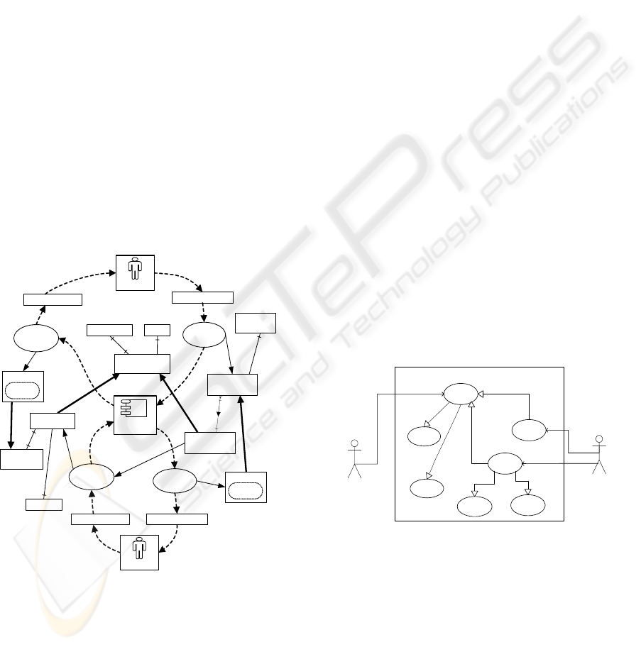
common goal. Interactions of one technical and two
organisational components are represented in fig. 7.
Figure 7: Description of Recruitment Service.
The presented graphical description of the
Recruitment service is consistent with the service
layer specification, which is illustrated in figure 6.
Coherent set of interactions are supported by one
software component, which is called Recruitment
Service. (Note: the Reject action is not presented).
The Apply action is decomposed into two
operations: Send Application Data and Receive
Application Data. Send Application Data is the first
operation, which is supposed to create Applicant and
Application objects. The Receive Application Data
operation is not just delivering Application Data
flow to CEO, but also changes Application Status
state from ‘Unspecified’ to ‘Received’.
4 FROM SERVICE TO
OBJECT-ORIENTED
DIAGRAMS
Service-oriented diagram is defined in terms of
creation, termination or reclassification constructs,
which together provides the graphical representation
of service semantics. Being computation neutral,
service-oriented diagram is more comprehensible for
business experts as compared to object-oriented
diagrams. In this chapter, we will illustrate the
bridging rules from the basic service-oriented
constructs to object-oriented diagrams.
Use cases represent functionality that a software
component provides by interacting with actors.
Specification of a use case diagram is as follows: a)
Communication action is represented as a use case,
b) Software component, which plays role of a
service provider, defines service boundary of a
technical service, c) Service requester is represented
as a use case actor. Use case diagram of a
Recruitment Service is illustrated in figure 8.
Figure 8: Use case diagram.
Any communication action can be considered as
separate function in the use case diagram. Use cases
are decomposed into the component layer actions by
using <<include>> and <<extends>> relationship.
According to our example, if the Apply action is
triggered, then two different outcomes are possible:
either Employ, or Reject. According to the service-
oriented diagram, one of the successive actions must
always take place. Such detail is not included into
the presented use case diagram.
Application Data
Receive
Application
Data
Send
Application
Data
Employment Data
Employment
Person
NameSS Number
Application
Reference
Number
Position
Receive
Employment
Data
Application Data
Application
Status =
Received
Employment
Status =
Received
Employee
Send
Employment
Data
Employment Data
Applicant
Recruitment
Service
CEO
Person
Recruitment Service
Person
Reject
CEO
Apply
Employ
«extends»
«extends»
Receive
Application
Data
Send
Application
Data
Receive
Employment
Data
Send
Employment
Data
«includes»
«includes»
«includes»
«includes»
ICEIS 2008 - International Conference on Enterprise Information Systems
192
Person CEORecruitment Management
Service
EmployApplicant
Receive
Employment
ChangeEmployment
Status
DeleteApplicant
DeleteApplication
CreateEmployee
CreateEmployment
Semantics of a use case can be represented by
using sequence and activity diagrams. We will limit
the process view examples just to activity diagrams.
The object-oriented operations, which define a use
case, can be elicited from the service-oriented
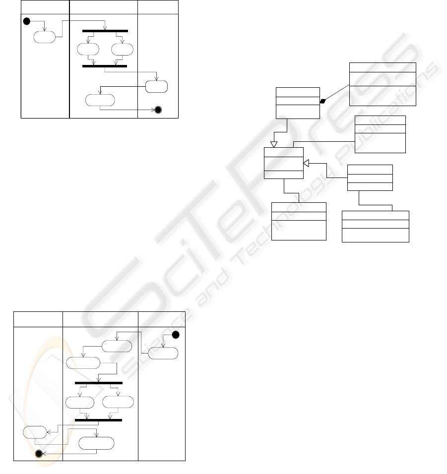
diagrams. A method for implementation of the
Apply action is defined by using UML activity
diagram, which is presented in figure 9.
Figure 9: Method of the Apply action.
The method of the Apply use case must include
two interface operations: Send Application and
Receive Application. Send Application operation
should trigger Create Applicant and Create
Application operations. According to semantics of
service-oriented events, Receive Application
operation is executed together with a Change
Application Status operation that is initialising state
of an Application object with the status ‘Received’.
Use case Employ consists of two interface opera-
tions: Employ Applicant and Receive Employment.
The remaining domain operations are predefined by
the service description as well. The corresponding
UML activity diagram is represented in figure 10.
Figure 10: Method of the Employ use case.
The precondition and postcondition object
classes that are defined by the service description
can be implemented in a number of ways. In the
presented example, all service description classes are
viewed as independent UML domain classes.
Corresponding domain class operations are
prescribed by the reclassification, creation and
removal events. Employ Applicant is a
reclassification event that creates Employee object
and removes Applicant object.
Conceptual representation of Recruitment Service
prescribes two types of interface classes – one for a
Person and one for CEO. For instance, Send Appli-
cation and Receive Employment operations must be
included into Interface Person class. Receive
Application and Employ Applicant operations are
defined in the Interface CEO class. Class diagram is
illustrated in figure 11.
Figure 11: Class diagram.
If CEO decides to employ an applicant, then Employ
Applicant operation is triggered in the Interface
CEO class. According to the presented service
description, Employ Applicant action requires both
to Create Employee and to Delete Applicant. Crea-
tion of a new Employee object requires creation of
an Employment class object as well. That is why
Create Employee operation is defined in a sequence
with the Create Employment operation. Since an
Applicant is composed of an Application, the cre-
ation of an Applicant object is synchronised with
creation of an Application object (see Delete Appli-
cation, Delete Applicant and Create Applicant and
Create Application operations in both activity dia-
grams) as well. The communication loop is com-
pleted, when a person receives Employment Data.
This information flow is provided by the Receive
Employment operation, which is placed in the Inter-
face Person class. As it is prescribed by service-
oriented diagram, Receive Employment is executed
in sequence with Change Employment Status
operation. In general, if the termination event takes
place, then all objects in more specific classes are
terminated as well (see inheritance links). This rule
+CreatePerson()
Person
-SS_Number
-Name
+CreateEmployee()
Employee
-Position
+CreateApplicant()
+DeleteApplicant()
Applicant
+CreateApplication()
+DeleteApplication()
+ChangeApplicationStatus()
Ap plic ation
-ReferenceNumber
-Status : char = Not Received
1
1..1
+CreateEmployment()
+ChangeEmploymentStatus()
Employment
-Status : char = Not Received
1
1
+SendApplicationData()
+ReceiveRejection()
+ReceiveEmployment()
InterfacePerson
+ReceiveApplication()
+RejectApplication()
+EmployApplicant()
InterfaceCEO
1
1
Person CEORecruitment Management
Service
Send
Application
Receive
Application
Create
Applicant
Create
Application
Change
ApplicationStatus
INTRODUCING SERVICE-ORIENTATION INTO SYSTEM ANALYSIS AND DESIGN
193

is not relevant for the objects of more generic
classes. If an object is terminated in a more specific
class, then objects of the more generic classes are
still preserved.
5 CONCLUDING REMARKS
Implementation bias of many information system
modelling methods is a big problem, since the same
implementation oriented foundations are applied in
system analysis phase, without rethinking these
concepts fundamentally. Conceptual representations
of service architectures define computation
independent aspects of business processes, which are
not influenced by the implementation dependent
solutions. Semantics of service-oriented events were
explained in object-oriented design terms. We
concluded that UML notation is inconvenient for
systematic analysis of the service-oriented events. It
creates difficulties in validation of the diagrammatic
solutions by business process analysis experts.
Disparate diagrams are prone to inconsistencies, dis-
continuities and ambiguities. Service-oriented
constructs are quite comprehensible and can be
communicated among business experts and
designers more effectively than a set of various
types of implementation dependent object-oriented
diagrams.
Our approach is aiming at an engineering process
that is based on one model, which is used to
conceptualise service architecture before the
supporting technical system is defined. We have
demonstrated a way of bridging from the service-
oriented representations to object-oriented diagrams.
Service-oriented constructs predefine semantic
details that were used for elicitation of the object-
oriented operations. One obvious advantage of
conceptual representation of service architecture is
an integration of the static and dynamic aspects. Our
experience in analysing system specifications by
using computation independent notation demons-
trates that service-oriented events are more compre-
hensible. Service-oriented diagrams have no imple-
mentation bias and therefore they bridge a commu-
nication gap among system designers and business
analysis experts more effectively.
REFERENCES
Blaha, M. & Rumbaugh, J. (2005), Object-Oriented
Modelling and Design with UML, Pearson, London.
Booch, G., Rumbaugh, J. & Jacobsson, I. (1999), The
Unified Modelling Language User Guide, Addison
Wesley Longman, Inc., Massachusetts.
BPMN Working group (2004), Business Process
Modelling Notation, www.bpmn.org
Dietz J. L. G. (2001) DEMO: Towards a Discipline of
Organisation Engineering, European Journal of
Operational Research (128), Elsevier Science, 351-363.
Dori, D. (2002), Object-Process Methodology: A Holistic
System Paradigm, Springer, Berlin.
Erl, T. (2005). Service-Oriented Architecture: Concepts,
Technology, and Design, Pearson Prentice Hall,
Crawfordsville, Indiana.
Gustas, R & Gustiene, P (2002), Extending Lyee
Methodology using the Enterprise Modelling
Approach, Frontiers in Artificial Intelligence and
applications, IOS Press, Amsterdam, pp. 273-288.
Gustas, R. & Jakobsson, L. (2004) Enterprise Modelling
of Component Oriented Information System
Architectures, New Trends in Software Methodologies,
Tools and Techniques, IOS Press, pp. 88-102.
Gustas, R. & Gustiene, P. (2004) Towards the Enterprise
Engineering Approach for Information System
Modelling across Organisational and Technical
Boundaries, Enterprise Information Systems V,
Kluwer Academic Publisher, Netherlands, pp. 204-215.
Gustas R & Gustiene P, (2007) Service-Oriented
Foundation and Analysis Patterns for Conceptual
Modelling of Information Systems, ISD’2007,
Springer.
Gottschalk, K., Graham, S., Kreger, H., Snell, J. (2002),
Introduction to Web Services Architecture, IBM
Systems Journal, Vol. 41, pp. 170-177.
Harel, D. & Rumpe, B., (2004), Meaningful Modeling:
What’s the Semantics of ‘Semantics’?, IEEE
Computer, October, pp. 64-72.
Kim, J., Hahn, J. & Hahn, H. (2000), How Do We
Understand a System with (So) Many Diagrams?,
Information System Research, Vol.11, No.3, pp. 285 –303.
Krafzig, D., Banke, K. & Slama, D. (2005) Enterprise
SOA: Service Oriented Architecture best Practices,
Prentice Hall, New Jersey.
Lankhorst, M. et al. (2005), Enterprise Architecture at
Work, Springer, Berlin.
Maciaszek, L. A. (2005), Requirements Analysis and
System Design, Addison Wesley.
de Moor, A. (2005), Patterns for the Pragmatic Web, Proc.
Of the 13
th
International Conference on Conceptual
Structures, Kassel, Germany, LNAI, Springer, Berlin,
pp. 1-18.
Szyperski, C. (1998), Component Software – Beyond
Object-Oriented Programming, Reading, MA:
Addison-Wesley.
Yu, E. & Mylopoulos, J. (1994), From E-R to 'A-R' -
Modelling Strategic Actor Relationships for Business
Process Reengineering, 13
th
International Conference
on the Entity - Relationship Approach, Manchester.
Zachman, J. A. (1996), “Enterprise Architecture: The
Issue of the Century”, Database Programming and
Design Magazine.
Zimmerman, O., Krogdahl, P. & Gee, C. (2004), Elements
of Service-Oriented Analysis and Design, www-
128.ibm.com/developerworks/library/ws-soad1/
ICEIS 2008 - International Conference on Enterprise Information Systems
194
