
MANAGING REQUIREMENTS CHANGE AS PLM PROCESS
Mourad Messaadia, Jacqueline Konaté and Abd-El Kader Sahraoui
LAAS-CNRS, Université de Toulouse, 7, avenue du Colonel Roche,31007 Toulouse Cedex 4, France
Keywords: Requirements Engineering, Product Life Cycle Management, System Engineering, Collaboration
Engineering.
Abstract: This paper is on PLM issues within a systems engineering framework. The study considered is mainly
focused on requirements change issue how to integrate it into the PLM information systems. The
contribution is in two steps. Firstly, analyze requirements evolution engineering in terms of collaboration
processes. Secondly, we consider both the final product and requirements change impact on enabling
product, then we illustrate the approach by a case study.
1 INTRODUCTION
One of the most challenges in systems engineering is
the requirements change management. Indeed,
requirements change analysis and implementation in
a system engineering perspective using existing
manufacturing process can be extremely complex
and difficult to master. Requirements Management
is a sub process of Requirements Engineering
(Coulin, 2007). Since requirements can change any
time, their management must covers system life
cycle in order to take account requirements
evolution.
Currently, the required information to effectively
and efficiently manage the complete product
lifecycle: handling requirements change and
managing both end products and enabling products
of the manufacturing process, are more often
distributed among several different systems that are
not integrated. The PLM (Product Lifecycle
Management) platform covers all steps in the
product lifecycle. However, PLM unfortunately
lakes of requirements change handling techniques.
For an enterprise using PLM platform, exploring
new concepts and taking advantage of new
technologies lead to requirements change through
this platform. So, it is important to firstly investigate
what additional solutions and improvements of PLM
(Product Lifecycle Management) can provide
solution for requirements change problems; and then
consider a technique to integrate requirements
change process within system engineering for
manufacturing using PLM.
It is important to note that collaboration is
required in this process. Indeed, collaboration is an
efficient and effective way to address requirements
change.
This paper analyzes collaborative requirements
change process and proposes a mean to introduce
this process in PLM according system approach. A
simple illustration with about bicycle manufacturing
shows how our approach can be implemented and
transferred into practice. This example is easy to
understand, and does not require substantial
background explanation.
The remainder of this paper is organized as
follow: Section 2 presents areas and concepts used
in the paper, section 3 is about collaboration in
requirements change, section 4 presents PLM and
shows requirement change thought product lifecycle,
section 5 illustrates our approach through a bicycle
example and finally conclusions and perspectives
are presented in section 6.
2 BACKGROUND
Requirements changes can cause significant
problems leading ripple effects through
manufacturing system and product development
process. It is obvious that early detection and
correction of the potential problems during
requirement analysis phase may considerably
alleviate a lot of problems later during testing and
maintenance. Unfortunately, for any system, all
change requests do not occur during the first steps of
224
Messaadia M., Konaté J. and Kader Sahraoui A. (2008).
MANAGING REQUIREMENTS CHANGE AS PLM PROCESS.
In Proceedings of the Tenth International Conference on Enterprise Information Systems - ISAS, pages 224-230
DOI: 10.5220/0001689602240230
Copyright
c
SciTePress
system development. In addition, almost current new
systems are an evolution of existing systems
(aircrafts, robots, telecommunication, etc.), and most
of change occurs in these cases: the change of the
design/implementation, integrating new technologies
without changing the functional requirements, and
change the functional requirements of product by
adding new requirements as security. Adding,
deleting and modifying are the three types of
requirements changes.
Since systems are increasing large and complex,
requirements traceability (Sahraoui, 2005) became
necessary in the development process. Once the
traceability is defined through a traceability model,
the consequences of upgrades can be more obvious.
Traceability allows predicting dependencies between
requirements and the parts of the system, and it can
decrease costs. Indeed, the cost is dependent of the
number of changes needed for a requirement, i.e.
implementation effort of a requirement change. The
traceability process can be described in two
manners: Backward (from design to System
Requirement Specification: SRS) and Forward (from
SRS to design) (Jamal, 2006). In this paper we use
the traceability process to make the link between the
different parts of the system.
In the example that we adopted, new
requirement is related to comfort (comfortable
bicycle) what results into the addition of shock
absorber. It acts to add a new requirement about
spring, then evaluate the impact of this change on
other parts of bicycle (frame, fork, sit). The next
phase is the realization of this change and finally its
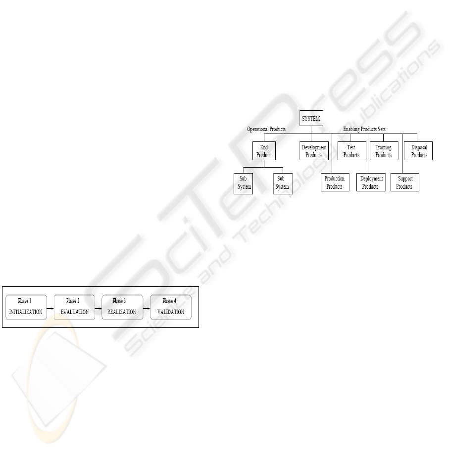
validation. The figure 1 shows the four different
phases of our requirements change process.
Figure 1: Requirements change process.
2.1 Systems Engineering
The International Council on Systems Engineering
(INCOSE) defines Systems Engineering as “an
interdisciplinary approach and means to enable the
realization of successful systems. It focuses on
defining customer needs and required functionality
early in the development cycle, documenting
requirements, then proceeding with design synthesis
and system validation while considering the
complete problem including manufacturing and
testing” (INCOSE, 2008). Subsequently we have
selected the EIA-632 standard (ANSI/EIA-632-
1998, 1998) as a suitable Systems Engineering
framework to found our approach. Accordingly we
consider the final product of a manufacturing
process as a system. As shown in figure 2, system
has logical and physical composition: operational
products and enabling products. Operational
products include end product as well as sub-
assemblies, sub-parts, and sub-products. The
enabling products are products which support and
which are involved in operational products
manufacturing, such as machinery and tools. So,
enabling products are concerned with performance
of manufacturing process, whereas operational
products tend to be either inputs or outputs of
process itself. It is possible to see that there may be
multiple end products for a single system, likewise
each sub system represents system its own end
products and the sets of enabling products.
Figure 2: System engineering framework (ANSI/EIA-632-
1998, 1998).
The application of this model to a bicycle: "end
product" is bicycle, sub systems are (Wheel, Pedals,
Saddle, Fork, Tire, ...) and the "enabling products"
which interest us is system of bicycle manufacturing
(Cutting and forming machines, Humans, ...). The
Product Life Cycle Management (PLM), a platform
for the system management covers above steps will
be presented in following subsection.
2.2 Product Life Cycle Management
The management of informations is central in
product development process. These informations
are from product definition, its manufacturing, and
its maintenance until its disposal. Managing such
information in complex industrial context requires a
systematic and controlled method. PLM is
considered as a strategic approach of information
management. PLM has emerged as the new method
in industrial companies to better manage product
development and manufacturing from the beginning
to the end of the product life cycle. Unlike to
Systems Engineering, now there are no PLM
MANAGING REQUIREMENTS CHANGE AS PLM PROCESS
225
standards for manufacturing processes. In most cases
the installation of PLM system requires redefinition
of various manufacturing processes, a better
communication and integration between both
internal and external related heterogeneous systems.
We propose a definition of PLM which states that
PLM is the integration of all data and information
systems related to all phases of a product lifecycle,
and processes concerned with managing this
information and relationships between those
systems. Subsequently we consider PLM as both a
short of Enterprise Application Integration (EAI)
tool managing the translations necessary for the
different systems to communicate, and also as a set
of defined processes that dictates the possible
interactions with PLM system and how those are
translated to the individual systems. Thus, we
consider PLM as both a system and a set of
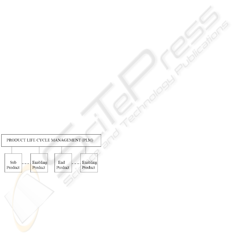
processes. Figure 3 shows a PLM system which
depends on integration of all systems concerned with
product life cycle. For example: SCM (Supply Chain
Management), ERP (Enterprise Resource Planning),
MES (Manufacturing Execution System), CRM
(Customer Relationship Management) and DMS
(Design Maintenance System) systems. This also
extends to systems supporting other major business
functions, such as sales and marketing, human
resources, and finance. Typically, much of
manufacturing information such as material bills,
production routings, work orders, sales orders,
purchase orders, and so on are found in the ERP
system.
Figure 3: A product life cycle management system.
We consider again our example. Once the
bicycle has been defined via SE and the new
requirement emitted has been identified, we need a
system which manages the information of product
(requirement and all decisions) during the phases of
life cycle, especially the manufacturing phase. For
this purpose, we adopted PLM approach by
highlighting collaboration aspect. Following
subsection addresses collaboration issue in
requirements change context.
3 COLLABORATION IN
REQUIREMENT
ENGINEERING
During the first steps of Requirements Engineering
such as Requirements Elicitation phase, people
express their requirements by communicating via
different means (text, images, e-mails,
conversations, meetings, etc.). So, it is important
that words have the same meaning for each
participant. To do to this, people must converge
towards same meaning of concepts. In (Briggs et al.,
2003) and (Fruhling et al., 2007), there are some
patterns of collaboration including “generate” and
“reduce” patterns. The former allows the move from
few to more concepts whereas the latter to move
from more concepts to few concepts. So, a “reduce”
pattern can be used bring convergence in concepts
signification. Likewise, in order to get many ideas or
concepts, we can rely on a “generate” pattern to
reduce the omission of requirements. Whatever the
measures to take during the initial phase of
requirements engineering, it is not possible to ensure
the completeness and the consistency of the set of
the overall requirements for the first time.
In order to evaluate requirements in
“harmonious” manner throughout system life cycle,
it is important to approach the problem
collaboratively. In collaboration, actors, their roles
and processes are essential. Next subsections present
these different points.
3.1 Collaboration Actors and
Requirements Dependencies
Here, actors are any all concerned with system
development: requirements engineers, system
designers, developers, other stakeholders and final
users. In other words, they are: engineers, users and
others stakeholders.
Involving of all these parts is necessary because
system is consisted by subsystems interoperating as
our bicycle. If there is a change in one subsystem,
other parts can be impacted by this change. For
example, let a change requirement request as: the
bicycle saddle must bear a person of 100 pounds.
This change brings requirements changes for wheels,
frames and other parts. Through requirements
traceability, it is possible to keep changes historic
and dependencies between requirements for further
analysis.
ICEIS 2008 - International Conference on Enterprise Information Systems
226
3.2 Collaboration Processes
The requirement change request is emitted by at
least one actor identified in the previous subsection.
(engineer, end user, other stakeholder) as showed in
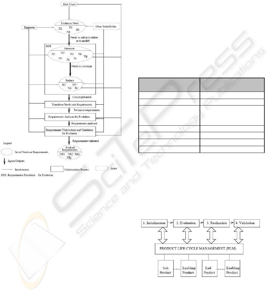
figure 4.
Figure 4: Collaborative requirements change process.
They start by express some needs (N1, N2, N3, and
N4). Then all people concerned with these changes
of needs can intervene by expressing all possible
ideas. This leads to several needs, i.e., generate
needs. Normally, during this step most of needs
change are identified and almost all their eventual
impacts. After, it is important to ensure that behind
every need expressed by participants, every
participant has the same idea about it and that there
are no redundancy. This allows convergence
between actors and reduces the number of needs to
be changed. Needs resulting from reduce step are
(N1’, N3’, Ni’, Np’). The other steps are classical
steps in the engineering requirements. The final
result is a set of new requirements (NR) or evolved
requirements (NR1, NR2, NRi, NRj). Since PLM
allows collaboration and it covers system life cycle,
in next subsections we integrate these considerations
in system engineering processes in the PLM context.
4 PRODUCT LIFE CYCLE FOR
SYSTEM ENGINEERING
This section explains how requirements change can
be managed using PLM in System Engineering
context. We achieve this by detailing what PLM
must provide in order to satisfy the request of this
requirements change at each phase of the process.
Table 1 presents relationships between data in
systems engineering phases and product lifecycle
management phase. In our example about bicycle,
final end product (or system) would be finished and
complete bicycle. Subsystems would include things
like wheels, handlebars, and frame.
Table 1: Relationships between PLM data and systems
engineering phases.
Systems Engineering
phases
Product Lifecycle
Management data
Requirements
Design Change
Manufacturing Workflow
Structure
Inventory
Testing
Operation
Maintenance
Disposal
The figure 6 illustrates how PLM integrates
requirements change process and the top-down
approach of engineering system (system
composition). The Four phases shown in figure 6 are
described in detail in following subsections. In
addition, inputs, outputs and data handled in
different corresponding steps are presented in the
tables.
Figure 6: PLM for Requirements change process in
systems Engineering.
MANAGING REQUIREMENTS CHANGE AS PLM PROCESS
227
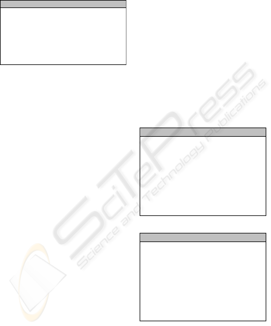
Table 2: Initialization process.
Input Steps Data Output
New or modified
requirement(s)
1. Identify change
• Applicant
• Type
• Rationale
2. Examine traceability
• Type
• Links
3. Assign resources
4. Submit request
Engineering
Change
Request
(ECR)
Phase 1: Initialization
Initialization phase in requirements change process
involves determining the sources and justifications
of change from system actors. When a requirement
change is initiated, PLM system provides the basis
for creation of an ECR (Engineering Change
Request). Person presenting ECR defines the change
context, items (parts, assemblies, or documents)
affected by this change, and a description of the
change reasons. An ECR can contain other
documents such as CAD (Computer Aided Design)
drawings. In PLM system, ECR is delivered to the
responsible of change according to the defined
workflow.
Phase 2: Evaluation
Evaluation phase in requirements change process
involves the development of possible solutions,
analysis of their impact, and make a decision. This
stage may also include some degree of prototyping
depending on complexity of required changes. It
may also include a formal manufacturability study
with feedback to design stage. This phase begins
when an ECR is emitted (it is also possible that an
ECO (Engineering Change Order) has been emitted
directly). ECR is delivered by PLM system to
responsible as defined in Workflow Management
System. When it is clear what kind of changes will
be made in the processes and products, actors of
changes can emit an ECO. The decision to make
about change request must take into account links
between required product changes, and required
changes within other processes like manufacturing
process. In the case of manufacturing, only complete
manufacturing process can provide necessary
perspective in order to identify from physical form
of product which parts, processes and components
are affected. It also highlights link between end
products (system and all subsystems) and enabling
products and also the manner to produce final
product. After all these steps, responsible will
generate an ECO within PLM system.
Phase 3: Realization
Realization phase of requirements change process is
more important and includes change implementation
across organization. This phase may also include
some prototypes.
Requirements change can cause one or more of
following required changes:
• Changes in process (new processes version
X+1)
• Changes in products (new version of products
Y+1)
• Changes in enabling products (new version of
enabling products Z+1)
Humans involved (collaboration actors) in the
process such as machine operators could be
considered as enabling products. They can also
change if the process they perform changes, e.g.
additional training.
Table 3: Evaluation process.
Input Steps Data Output
Engineering
Change
Request
(ECR)
•
Review system
documentation
• Determinate Impact
on process, end
products and
enabling products.
• Classify change and
explore similar
change
• Identify system
design impacts
• Specify and design
change
• Evaluate change
request
• Approval authority
Engineering
Change
Request
(ECR)
Decomposi-
tion of the
Systems
Traceability
of the
Requirements
Engineering
Change
Order (ECO)
Table 4: Realization process.
Input Steps Data Output
Engineering
Change
Request
(ECR)
•
Review system
documentation
• Determinate Impact
on process, end
products and
enabling products.
• Classify change and
explore similar
change
• Identify system
design impacts
• Specify and design
change
• Evaluate change
request
• Approval authority
Engineering
Change
Request
(ECR)
Decompositio
n of the
Systems
Traceability
of the
Requirements
Engineering
Change
Order
(ECO)
ICEIS 2008 - International Conference on Enterprise Information Systems
228
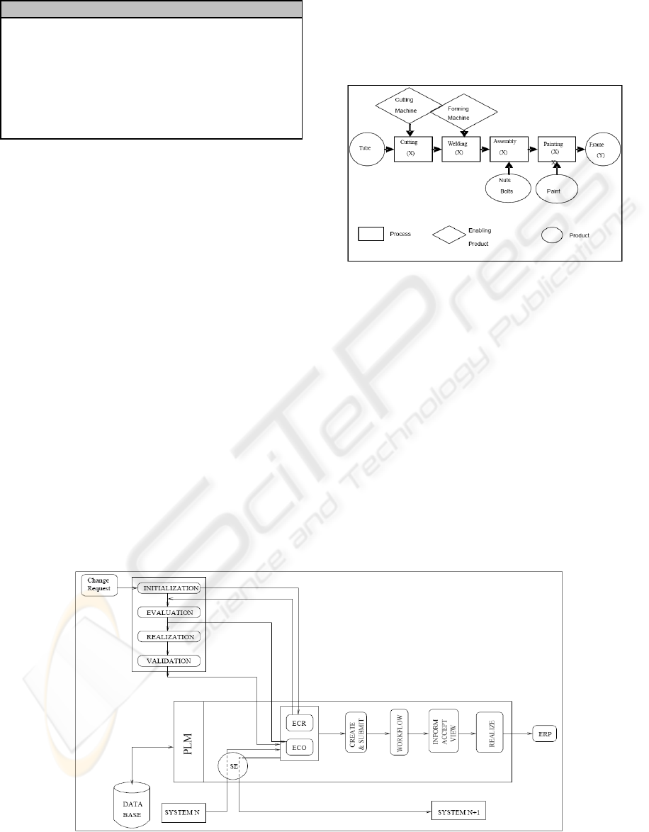
Table 5: Validation process.
Inpu
t
S
teps
D
ata Outpu
t
Verification
planning
• Generate test cases
for the change
• Update test suite
• Perform
integration testing
• Conduct
acceptance testing
• Approve change
Change
approval
Phase 4: Validation
Validation may occur in many levels during an
extended period. Indeed, this phase is a set of steps
of verification by testing. For example, if response
come as a result of customer request, then validation
process must is applied until end users arrive to use
new final product.
5 APPLICATION TO BICYCLE
SYSTEM
In this section we apply our approach to an example
manufacturing process. Each association between
product and production systems can be managed as a
connection between systems of each hierarchical
system structure.
In example of the bicycle (see Figure 7), we can
see manufacturing process (X) which defines
manufacturing of all parts of bike until to get end
product. PLM system manages decisions when new
requirement is emitted, for example, adding a spring
in bicycle frame. In fact, when requirement is
emitted, it is transferred via PLM towards a team.
This team takes into account initial links between
bicycle and its manufacture system in order to define
impact of adding a spring to bicycle. PLM is
responsible to convey ECR emission to be validated
in order to establish new bicycle (Y+1) with spring
and its new manufacturing processes (X+1).
Figure 7: Bicycle Frame Manufacturing Process.
PLM is also responsible to safeguard and bring up to
date new product and its manufacturing process (see
Figure 8). In the figure 8, collaboration occurs at
every step in accordance with what has been
established in section 3 about collaboration.
Initialization phase matches to “Evolution Need”
phase in term of collaboration. Similarly phases of
evaluation and realization phases correspond to the
“generate” and “reduce” in the sense of
collaboration. By integrating system engineering
(SE) approach in PLM, a new system (SYSTEM
N+1) is constructed. The collaborative processes are
also taken into account and defined in advance. All
versions of system are stored in a data base (DATA
BASE).
Figure 8: Bicycle Frame Manufacturing Process.
MANAGING REQUIREMENTS CHANGE AS PLM PROCESS
229

6 CONCLUSIONS
AND PERSPECTIVES
The link established by SE allows us to identify the
change impact in product and into manufacturing
system. This paper defines new processes of
manufacturing from requirement change. Since one
essential purpose of PLM is to allow collaboration
between people, we also integrate collaboration aspect
into PLM. However, we do not always know some
data to be exchanged through the steps of product life
cycle like shown in table 2 and 5. These issues will be
addressed by further research study.
ACKNOWLEDGEMENTS
We would like to thank Coulin chad and El-Jamal
Hani for their collaboration and the useful comments
on early drafts of this paper and the discussions on
requirements elicitation and evolution.
REFERENCES
ANSI/EIA-632-1998 EIA (1998). EIA Standard: Processes
for Engineering a System.
Coulin, AEK. Sahraou and Zowghi (2005). Towards a
collaborative and combinational approach to
requirements elicitation within a systems engineering
framework. 18th International Conference on Systems
Engineering (ICEng'05), Las Vegas (USA).
Coulin, C.: A Situational Approach and Intelligent Tool for
Collaborative Requirements Elicitation. Phd thesis,
LAAS report 07636. University of Sydney and Université
de Toulouse, 2007.
INCOSE: What is System Engineering. http://
www.incose.org/practice/whatissystemseng.aspx,
accessed in March 2008.
Jamal, AEK. Sahraoui (2005). Customising systems
engineering concepts: case study on concurrent
engineering Context. ESEC, European symposium on
concurrent engineering systems.
Jamal: Contribution à l'évolution des exigences et son
impact sur la sécurité. Phd. Thesis, University Paul
Sabatier, sept. 2006.
Lardeur, C Auzet. (2003). Deployment of SE including
Manufacturing Systems development: Theoretical
Aspects. The 13th Annual International Symposium
INCOSE, Washington, DC, USA.
Messaadia, M.H, El-Jamal and AEK Sahraoui (2005)
Systems Engineering Processes Deployment for PLM.
Saaksvuori, A, A. Immonen (2004). Product lifecycle
Management. Springer-Verlag Berlin. Heidelberg
www.incose.org INCOSE (2005).
Konaté, J. and Sahraoui A.E.K. (2007). Collaboration in
Requirement Engineering Process. In Proceedings: 13th
International Conference on Concurrent Enterprising,
Sophia Antipolis, France, 04-06 June 2007.
Briggs R.O., de Vreede G. J., Nunamaker and J. F. JR
(2003). Collaboration Engineering with ThinkLets to
Pursue Sustained Success with Group Support Systems.
Journal of Management Information Systems, 19(4): 31-
64.
Anderson S. and Felici M.(2003) Quantitative Aspects of
Requirements Evolution. In Proceedings of 26
th
Annual
international Conference in Computer Software and
Applications, 27- 32
Hassin J., Rilling J. and Hewitt J. (2005). Change impact
analysis for requirement evolution using use case maps.
In Proceedings of the Eighth International Workshop on
Principles of Software Evolution, 81-90
ICEIS 2008 - International Conference on Enterprise Information Systems
230
