
A CONCEPTUAL SCHEME FOR COMPOSITIONAL
MODEL–CHECKING VERIFICATION OF CRITICAL
COMMUNICATING SYSTEMS
Luis E. Mendoza Morales
1
, Manuel I. Capel Tu˜n´on
2
, Mar´ıa A. P´erez
1
and Kawtar Benghazi Ahklaki
2
1
Processes and Systems Department, Sim´on Bol´ıvar University, PO Box 89000, Caracas 1080-A, Venezuela
2
Software Engineering Department, University of Granada, Aynadamar Campus, 18071 Granada, Spain
Keywords:
Real–time software systems, Compositional verification, Model–checking.
Abstract:
When we build complex business and communication systems, the question worth to be answered: How
can we guarantee that the target system meets its specification? Ensuring the correctness of large systems
becomes more complex when we consider that their behaviour is the result of the concurrent execution of
many components. This article presents a compositional verification scheme, that integrates MEDISTAM–
RT (Spanish acronym of Method for System Design based on Analytic Transformation of Real-Time Models),
which is formally supported by state–of–the–art Model–Checking tools. To facilitate and guarantee the veri-
fication of large systems, the proposed scheme uses CCTL temporal logic as the property specification formal
language, in which temporal properties required to any system execution are specified. In its turn, CSP+T
formal language is used to formally describe a model of the system being verified, which is made up of a set
of communicating processes detailing specific atomic–tasks of the system. In order to show a practical use
of the proposed conceptual scheme, the critical part of a realistic industry project related to mobile phone
communication is discussed.
1 INTRODUCTION
Nowadays, computer systems are used in almost all
realms of human life. The term pervasive systems
has become popular when we are talking about the
human–computer interaction in which information
processing has been thoroughly integrated into every-
day business and activities. There are systems, such
as the ones related with electronic commerce, tele-
phonic nets, train control and air traffic control, in
which a failure is unacceptable. Thus, the reliability
of this kind of system should be guaranteed. Design
and verification methods have been developed over
recent years to give a response to this non–functional
requirement and for guaranteeing their correctness.
In order to contribute to the achievement of this
objective, a compositional verification scheme that
integrates MEDISTAM–RT —Spanish acronym of
Method for System Design based on Analytic Trans-
formation of Real–Time Models— (Benghazi et al.,
2007) is presented in this paper, which can be proved
as a sound verification approach since it is based on
the formal aspects of Model–Checking (MC). The
integration is attained by using two formalisms that
are under the same formal semantics of Kripke struc-
tures
1
: CCTL for temporal properties and CSP+T for
system processes formal specification. To show the
usefulness of our proposal, the application of the ver-
ification scheme is presented by means of a case study
that has critical temporal requirements.
Thanks to the compositionality that present the
aforementioned specification languages and a pos-
sible common interpretation, semantically compati-
ble, of the models they describe, state–of–the–art MC
tools can be incorporated to facilitate the verification
of some complex software systems.
Similar works about combining compositional
verification and MC can be found in the literature.
Some of these (Clarke et al., 1989; Grumberg and
Long, 1991; Bultan et al., 1996) use the composi-
1
Called also a transition graph, consists of a set of states,
a set of transitions between states, and a function that labels
each state with a set of properties that are true in this state
(Clarke et al., 2000).
86
E. Mendoza Morales L., I. Capel Tuñón M., A. Pérez M. and Benghazi Ahklaki K. (2008).
A CONCEPTUAL SCHEME FOR COMPOSITIONAL MODEL–CHECKING VERIFICATION OF CRITICAL COMMUNICATING SYSTEMS.
In Proceedings of the Tenth International Conference on Enterprise Information Systems - ISAS, pages 86-93
DOI: 10.5220/0001697500860093
Copyright
c
SciTePress
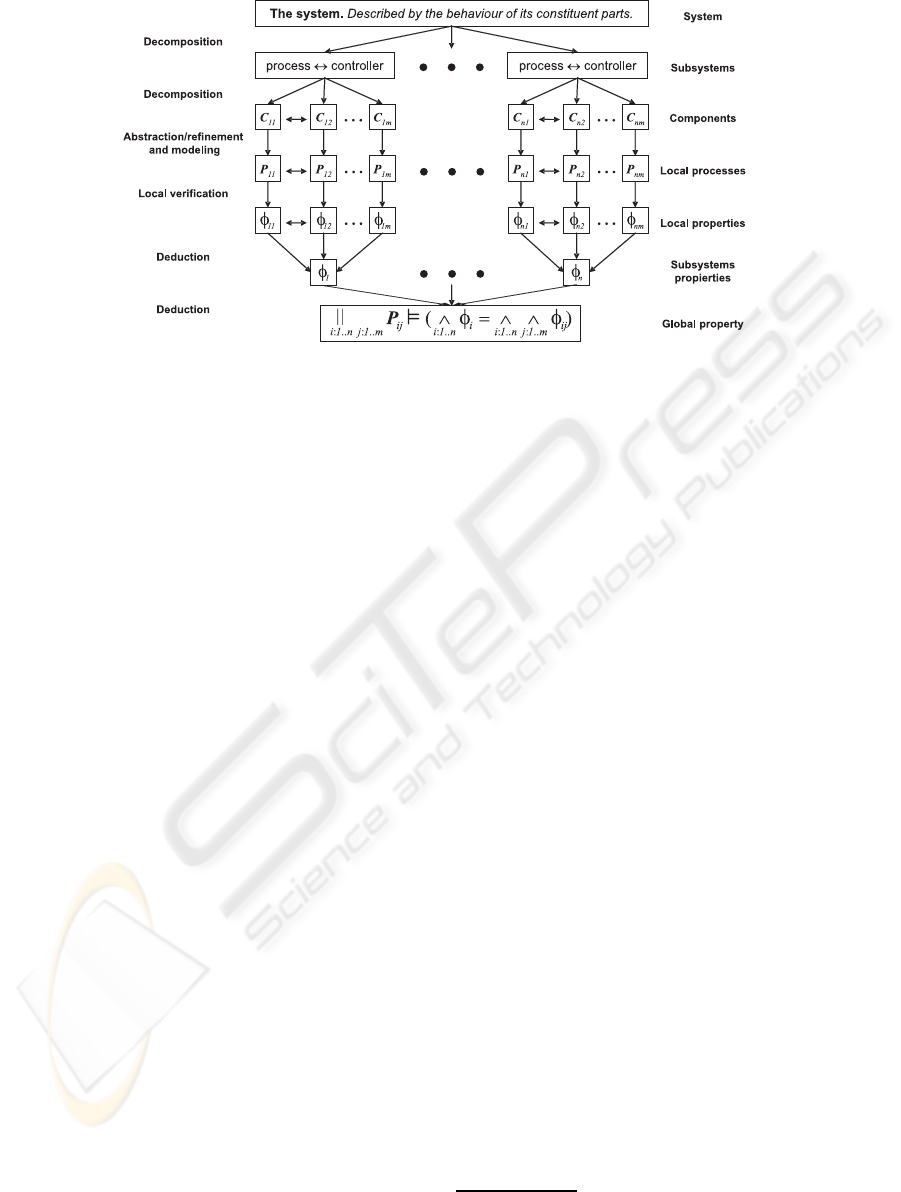
Figure 1: The proposed compositional verification scheme. Adapted from (Mendoza and Capel, 2007).
tional capacity of temporal logics to address the com-
plex software systems verification problem. Whereas
others, such as (Giese et al., 2003; Yeh and Young,
1991), take advantage of the process algebra opera-
tors to allow the checking of the system behaviour
with respect to its predefined properties. Differently
from other research, our work is aimed at giving a sys-
temic, integrated vision of analysis, design and verifi-
cation tasks, by incorporating the use of MC tools in
the system development cycle within a compositional
verification framework so as to allow the verification
of the complete system design.
The paper is organized as it follows. In the next
section, we give a brief description of our composi-
tional verification scheme and MEDISTAM–RT de-
sign method. Then, we give the formal framework
(CCTL and CSP+T) used in the MC technique inte-
grated into the scheme. Afterwards, we establish how
CCTL and CSP+T are combined into the MC tech-
nique. Finally, we apply our proposal to a real project
related to mobile phone communication. The last sec-
tion gives our conclusions and discusses future work.
2 INTEGRATED ELEMENTS
2.1 Compositional Verification
In order to mitigate complexity, modular software de-
velopment makes use of system decomposition and
abstraction/refinement concepts. Every module, or
more accurately, each system component, is individu-
ally verified, and its results are deductively combined
to obtain the system global characteristics. More-
over, the behaviourof the entire system can be derived
from descriptions of system components (Lukoschus,
2005; Mendoza and Capel, 2007), it being unneces-
sary to take into account any other information about
modules or components’ internal structures (black
box principle (Lukoschus, 2005)). Figure 1 shows the
proposed compositional scheme.
Decomposition. The initial division of the system
into smaller modelling entities is gradually performed
until the smallest possible entity’s level is reached,
which corresponds to capsules (according to UML–
RT
2
).
Abstraction, Refinement and Modelling. Each
subsystem or component needs to be modelled at the
correct abstraction level. These models should be as
abstract as possible, but keeping the details needed to
infer the properties of their observable behaviour. The
described compositional approach ought to be able
to conciliate both apparently opposing descriptions
of system’s components (the rather abstract structural
view and the behavioural one).
Local Verification. Every system component
should be tested against its formal specification. This
step can be automatically carried out by using MC.
Deduction. In order to check the global system
properties, the local processes specifications are com-
posed by using the laws of process algebra and
CSP+T operators. The properties specification, by
using logical conjunction operators, see Figure 1.
Hence, the complete system verification is achieved
by taking advantage of the CSP+T (
ˇ
Zic, 1994) and
2
An extension to UML which adds four new building
blocks to the standard UML: capsules, ports, protocols, and
connectors (Selic and Rumbaugh, 1998).
A CONCEPTUAL SCHEME FOR COMPOSITIONAL MODEL–CHECKING VERIFICATION OF CRITICAL
COMMUNICATING SYSTEMS
87
CCTL (R¨uf and Kropf, 1997) compositional capaci-
ties with the use of deductive techniques (Lukoschus,
2005).
2.2 MEDISTAM–RT
With MEDISTAM–RT we can perform the specifica-
tion of the structural and behavioral aspects of RTSs
systematically (Benghazi et al., 2007). These two dif-
ferent viewpoints of a system are usually attained in
UML–RT by using class and composite structure dia-
grams, and by using state machine diagrams, respec-
tively. We apply a transformational method, based
on a proposed set of transformation rules (Benghazi
et al., 2007), which allow us to create a CSP+T model
from a UML–RT analysis model of a given RTS. As
can be seen in Figure 2, MEDISTAM–RT is divided
into two main phases: the first one (top–down mod-
elling process) to model the system using UML–RT,
while the second one (bottom-up specification pro-
cess) obtains the formal specification in CSP+T by
the transformation of each UML–RT submodel.
2.3 Formal Framework
2.3.1 CCTL
Clocked Computation Tree Logic (CCTL) (R¨uf and
Kropf, 1997) is a temporal logic extending CTL
(Clarke et al., 2000) with quantitative bounded tem-
poral operators. CCTL is used to reason with se-
quences of states, where a state gives a time interpre-
tation of atomic propositions at a certain time instant
and time is isomorphic to the set of non–negative in-
tegers. See (R¨uf and Kropf, 1997) for more details.
CCTL includes the CTL with the operators until
(U) and the operator next (X) and other derived opera-
tors in LTL, such as R, B, C and S, useful to facilitate
RTS properties specification. All “LTL-like” tempo-
ral operators are preceded by a run quantifier (A uni-
versal, E existential) which determines whether the
temporal operator must be interpreted over one run
(existential quantification) or over every run (univer-
sal quantification) starting in the actual configuration,
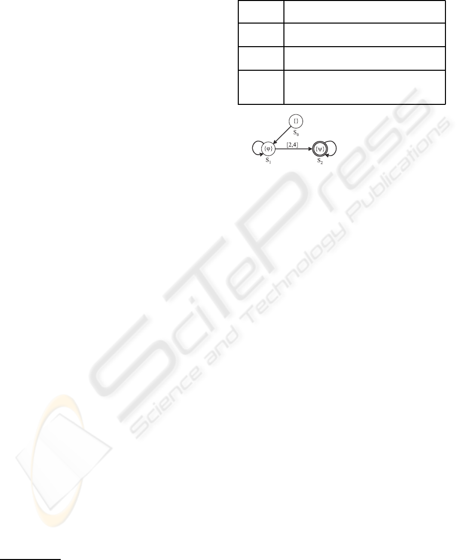
see (R¨uf and Kropf, 1997) for details. In the Table 1
can be seen a textual description of some temporal
operators usually deployed in CCTL specifications.
Interval logics allow us to carry out a logical rea-
soning at the level of time intervals, instead of in-
stants. Within our approach, the basic model for un-
derstanding RTS is the interval structure
3
Because
3
A state transition system with labelled transitions, as-
suming that every interval structure has exactly one clock
for the measure of time (R¨uf and Kropf, 1997).
Table 1: Informal description of the temporal operators.
ϕ and ψ are arbitrary CCTL formulae, and a ∈ N and
b ∈ N ∪ {∞} are time bounds.
X
[a]
ϕ
The formula ϕ has to hold after exactly
the time a.
F
[a,b]
ϕ
The formula ϕ has to hold at least once
within the interval [a,b].
G
[a,b]
ϕ
The formula ϕ has to hold at all time of
the interval [a,b].
ϕU
[a,b]
ψ
The formula ψ has to become true within
the interval [a,b] and all time steps before,
the formula ϕ has to be valid.
ϕU
[2,4]
ψ
Figure 3: Kripke structure example of a CCTL formula.
the CCTL MC algorithms represent sets of states and
transitions, we need to operate on entire sets rather
than on individual states and transitions.
Temporal logic MC takes a structure (representing
the system property) which is unwound into a model
and a formula, and automatically checks if the struc-
ture (model) meets the specification (formula). The
fundamental structures are timed Kripke structures
(unit–delay, temporal) (Clarke et al., 2000); i.e., the
model checker determines whether the Kripke struc-
ture is a model of the formula. Figure 3 shows a
graphical example (a B¨uchi automaton (Alur and Dill,
1994)) of the Kripke structure a CCTL formula.
2.3.2 CSP+T
CSP+T (
ˇ
Zic, 1994) is a real–time specification lan-
guage which extends Communicating Sequential Pro-
cesses (CSP) (Roscoe, 1997) to allow the description
of complex event timings, from within a single se-
quential process, of use in the behavioural specifica-
tion of RTS. CSP+T is a superset of CSP, as a major
change to the latter, the traces of events are now pairs
denoted as t.e, where t is the global absolute time at
which event e is observed. The operators, related with
timing and enabling–intervalsincluded in CSP+T are:
(a) the special process instantiation event denoted ⋆
(star); (b) the time capture operator (⋊⋉) associated to
the time stamp function a
e
= s(e) that allows stor-
ing in a variable a (marker variable) the occurrence
time of an event e (marker event) when it occurs; and
(c) the event–enabling interval I(T, t
1
).a, representing
timed refinements of the untimed system behaviour
and facilitates the specification and proof of temporal
ICEIS 2008 - International Conference on Enterprise Information Systems
88
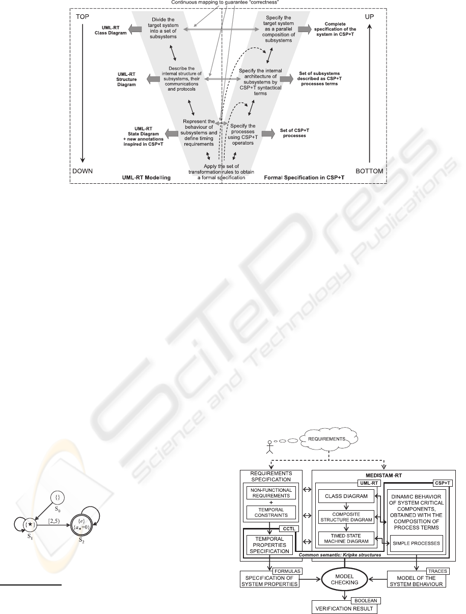
Figure 2: MEDISTAM–RT structure (Benghazi et al., 2007).
system properties (
ˇ
Zic, 1994).
CSP is a formal specification language that allows
descriptions of a process’ behaviour in terms of the
set of observed events sequences (traces semantic
4
)
(Roscoe, 1997). The set of all traces associated to pro-
cess P, traces(P), is denoted as τ(P) and uses several
notions of process refinement
5
(⊑). These ideas can
be extended automatically to CSP+T, because CSP+T
proposes some extensions to the traces model which
would allow the description of process timing proper-
ties (
ˇ
Zic, 1994).
CSP or CSP+T MC tools takes a process (rep-
resenting the system implementation), and automat-
ically checks whether the process fulfils the system
specification. B¨uchi automata (Alur and Dill, 1994)
have emerged as formal models derived from Kripke
structures (Clarke et al., 2000) to allow the analysis
and verification of system behaviour. A variant of
these are timed B
¨
uchi automata (TBA), see Figure 4,
which are able to describe the time at which events
happen on any system run and the temporal proper-
ties holding in the next possible set of system states.
P = 0.⋆ → I(2, 3).e → S
2
where:
a
⋆
= s(⋆) = 0
{e} ≡ occur(e)
Figure 4: Kripke structure example of a CSP+T process
term.
4
A trace is just a finite sequence of events, which may
be observed when a process is executing (Roscoe, 1997).
5
Since A and B are processes, we say that A refines B,
i.e., B ⊑ A, when process A is more deterministic than pro-
cess B, i.e., traces(A) ⊆ traces(B) (Roscoe, 1997).
3 OUR INTEGRATED VIEW OF
VERIFICATION
Figure 5 is a graphical summary of how the MC
concepts support the integration of MEDISTAM–RT,
UML–RT, CSP+T, and CCTL, into the compositional
verification scheme.
As we can observe in section 2.1, to perform the
system verification we need the specification of the lo-
cal processes that implement the system’s behaviour,
as well as the specification of properties that these
have to satisfy. Both the description of the system and
the specification of its properties must be oriented by
the system’s requirements.
The complete description of the system’s be-
haviour is obtained as result of using MEDISTAM–
Figure 5: Integrated view according to our compositional
verification scheme.
A CONCEPTUAL SCHEME FOR COMPOSITIONAL MODEL–CHECKING VERIFICATION OF CRITICAL
COMMUNICATING SYSTEMS
89

RT. A series of system views represented by class
diagrams, composition structure diagrams and state–
machines are obtained when the concepts of decom-
position, abstraction/refinement and modelling, fol-
lowing the alignments of UML–RT, are applied. After
that, these views are specified through CSP+T process
terms, which share a refinement and satisfaction rela-
tionship equivalentto the one existingbetween UML–
RT diagrams. To have a better detail of this relation-
ship, review the work in (Mendoza et al., 2007; Men-
doza and Capel, 2007).
In parallel to the abovedescribed process, the non-
functional requirements and temporal constraints that
the system must fulfill are specified with CCTL for-
mulas.
Once the CSP+T process terms and the CCTL
formulas are obtained, we can proceed to the sys-
tem’s verification in the same semantic domain given
by Kripke’s structures. As you can see in the Fig-
ures 3 and 4, we can translate a CCTL formula and
a CSP+T process term to a graphical Kripke struc-
ture (i.e., a B¨uchi automaton) that allow to compare
these specifications. By using MC tools it is possible
to check whether CSP+T process terms (which con-
stitute a possible model of the system under develop-
ment) satisfy the expected temporal behaviour of the
system specification given by CCTL formulas (sys-
tem’s properties). As result, we obtain the verification
of local system processes through the interpretation of
boolean expressions (True, False).
Formally, it is possible to assure and get the com-
plete verification of the system by using the relation-
ship
6
:
n
i:1...n
n
j:1...m
P
ij
^
i:1...n
^
j:1...m
φ
ij
(1)
4 CASE STUDY
A way to validate a scheme’s applicability and consis-
tency is by applying it to a case study. To this end, we
selected a real project related to mobile phone com-
munication. The aim was the verification of an ap-
plication whose estimated daily transaction volume
is in the order of millions. The case study is re-
lated to monitoring the state of cell sites
7
(CSs). A
CS is composed of a tower or other elevated struc-
ture for mounting antennas, and one or more sets of
6
The operators k, , and ∧, denotes parallel composi-
tion, satisfaction, and conjunction, respectively.
7
A site where antennas and electronic communications
equipment are placed to create a cell in a mobile phone net-
work.
transmitter/receivers transceivers, digital signal pro-
cessors, control electronics, a GPS receiver for tim-
ing, regular and backup electrical power sources, and
sheltering. In Figure 6 a simplified scheme of case
study is shown.
Figure 6: Case study simplified scheme.
To obtain a good functioning of the network, it is
required to guarantee the integrity of the information
state of each one of the devices that constitute each
CS by using a Distributed Data Base (DDB) mod-
elling approach. Each CS has its local Data Base (DB)
and its own Distributed Data Base Manager (DDBM)
that sends to the rest of the CSs the changes occur-
ring in the devices that exist in the CS. After updat-
ing the local DBs at the rest of the CSs, its DDBM
sends a confirmation message to the CS that requested
the update, notifying the change. Moreover, there is
a DDBM for each CS. Therefore it is required that
the DDBMs globally assure the integrity, among the
n DDBM of the distributed data when they are up-
dated. These data are locally replicated for the n CSs
As part of the system integrity only one data update
of the DDBMs should be carried out at any one time.
In the following text, we show the scheme appli-
cation for verifying the component considered as the
most critical for one of these systems, the DDBM. It
should be noted that we present a simplified version
of this component.
4.1 Specification of Properties
In order to guarantee the data integrity between the
different local DDBB of the DDB, each DDBM must
satisfy the following conditions:
• Only one send–and–update message can be per-
formed at same time within [a, b] time interval:
φ
1
:= ¬EF
[a,b]
(SndMsg(s) ∧ SndMsg(s
′
)).
• The DDBM is in the state receiving message (s)
until the next message (s
′
) is sent, which occurs
ICEIS 2008 - International Conference on Enterprise Information Systems
90
within the [a, b] time interval:
φ
2
:= AG
[a,b]
(RcvMsg(s) →
A[RcvMsg(s) U
[a+1,b−1]
(¬RcvMsg(s) ∧
A[¬RcvMsg(s) U
[a+2,b]
SndMsg(s
′
)])]).
• The DDBM is in the state sending message (s
′
)
until the receiver sends the acknowledgement of
the previously received message (s), within the
[a, b] time interval:
φ
3
:= AG
[a,b]
(SndMsg(s
′
) →
A[SndMsg(s
′
) U
[a+1,b−1]
(¬SndMsg(s) ∧
A[¬SndMsg(s) U
[a+2,b]
RcvMsg(s) ∧ AckMsg(s)])]).
The dynamical state of the transmitted messages
must satisfy the following formulae:
• Every data message generated by the Sender
DDBM is eventually received and the sent state
holds until the confirmation message arrives, thus
setting the message state to acknowledged, within
[a, b] time interval:
φ
4
:= AG
[a,b]
(SndMsg →
AF
[a+1,b−1]
[SndMsg U
[a+2,b]
AckMsg]).
• Every data message generated by the Sender
DDBM is always confirmed by the Receiver
DDBM, i.e. the state of any sent message will
eventually change to acknowledged, within [a, b]
time interval:
φ
5
:= AG
[a,b]
(SndMsg → AF
[a+1,b]
[AckMsg]).
Finally, the DDBM which initiated the data up-
dating in the replicated servers must be assured that
all the acknowledgement messages have arrived be-
fore returning to its initial state:
φ
6
= ¬(AckMsg(s
1
) ∧ AckMsg(s
i−1
) ∧ AckMsg(s
i+1
) ∧
AckMsg(s
n
)) U
[a,b]
RcvConf .
To guarantee the liveness of the system, each
DDBM must be satisfy:
• Every data message generated by the Sender
DDBM will ultimately be confirmed by the
Receivers DDBMs within the [a, b] time interval:
φ
e
:= AG
[a,b]
(AF
[a,b−1]
SndMsg(s
i
) →
AF
[a+1,b]
[RcvConf(s
i
)]).
• Every data message generated by the Sender
DDBM will be granted infinitely often by the
Receivers DDBMs within the [a, b] time interval:
φ
j
:= AG
[a,b]
(AF
[a,b−1]
[¬SndMsg(s
i
)] ∨
AF
[a+1,b]
[RcvConf(s
i
)]).
4.2 DDBM Modelling
Since the solution is based on keeping data replication
globally coherent, we must model one DDBM taking
into account the following conditions:
• All the data are replicated in n different CSs, each
one of these is managed by a distinct DDBM
(DDBMs = {DDBM
1
, DDBM
2
, . . . , DDBM
n
}.
• The global data integrity is guaranteed by send-
ing the appropriate messages to the rest of the
DDBMs, SndMsg = {(s, r)|s, r ∈ DDBM ∧ s 6= r}.
• Each DDBM updates its local copy of global data,
then it has to send a message to the other DDBMs:
AckMsg(s) = Σ
r∈DDBM−{s}
1
′
(s, r).
• The states that can be reached by each one of
the DDBMs are: Inactive (before a local up-
date or a remote message reception), Waiting (ac-
knowledgement messages of data updates in re-
mote DDBMs), and Updating (one local update
requested by other DDBM).
• The states that can be reached by each one of
the messages in transit are: Not used, Dispatched,
Received, and Confirmed.
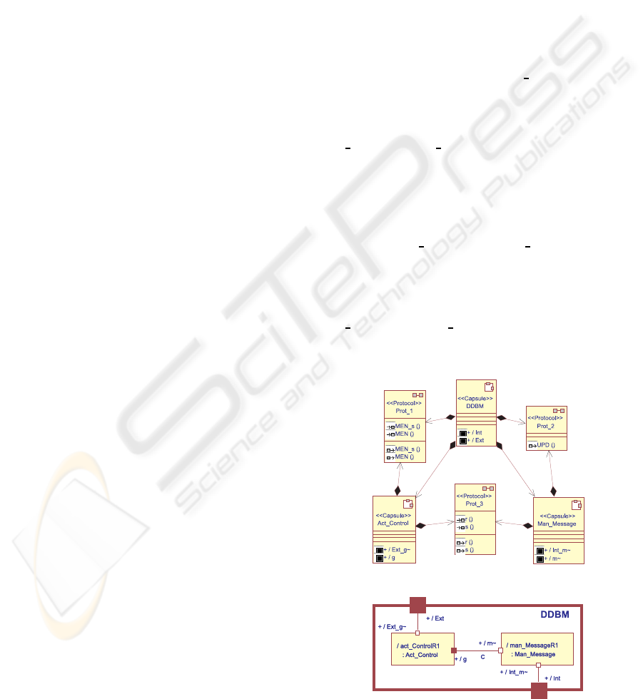
The architecture of each DDBM is shown in Fig-
ure 7. The DDBM is made up of two subcapsules,
Act Control y Man Message, both in charge of man-
aging the states of the DDBMs and the states of mes-
sages, respectively. Through the port Ext, the cap-
sule DDBM communicates with the others DDBMs
and through the port Int, the DDBM communicates
with the local DB. The communication between the
subcapsules Act Control and Man Message are car-
ried out through the connector C and the ports g y m,
respectively.
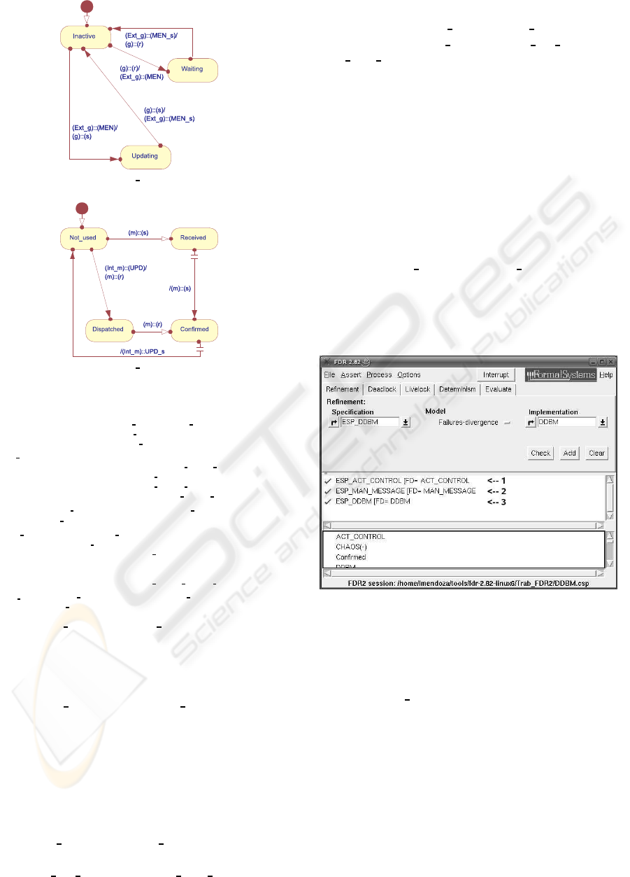
In Figure 8 we can observe the state machines that
model the behaviour of each one of the subcapsules
Act Control and Man Message.
The CSP+T process terms that specify the be-
haviours of prior UML–RT submodels are presented
(a) Class diagram
(b) Composite structure diagram
Figure 7: DDBM architecture.
A CONCEPTUAL SCHEME FOR COMPOSITIONAL MODEL–CHECKING VERIFICATION OF CRITICAL
COMMUNICATING SYSTEMS
91
(a) Act Control
(b) Man Message
Figure 8: State machines.
DDBM = CSP+ T
g,m
(Act Control, C, Man Message)
V
g
(CSP + T(Act Control))|[g
in
, g
out
]|C|[m
in
, m
out
]|
V
m
(CSP+ T(Man Message))
Act Control = ⋆.t
0
→ Inactive
Inactive = (g?r → (Ext g!MEN s → Waiting)
Ext g?MEN → (g!s → Updating))
Waiting = Ext g?MEN s → (g!r → Inactive)
U pdating = g?s → (Ext g?MEN s → Inactive)
V
Ext
g
(CSP + T(Act Control)) = {MEM, MEN s}
V
g
(CSP + T(Act Control)) = {s, r}
Man Message = ⋆.t
0
→ Not used
Not used = (m?s → Received
Int m?UPD → (m!r → Dispatched))
Received = m!s → Confirmed
Dispatched = m?r → Confirmed
Confirmed = Int m!UPD s → Not used
V
Int m
(CSP+ T(Man Message)) = {UPD, UPD s}
V
m
(CSP+ T(Man Message)) = {s, r}
Figure 9: Act Control and Man Message specification in
CSP+T terms.
in Figure 9. As the works (Mendoza et al., 2007;
Mendoza and Capel, 2007) demonstrate, adequate
DDBM, Act Control, and Man Message, CSP+T
process terms can be found to appropriately specify
the behaviour of the UML–RT submodels shown in
Figures 7 and 8.
4.3 Component Verification
First, we perform the verification of each subcom-
ponent (Act Control and Man Message) with respect
to the subproperties that they must each accom-
plish (ESP Act Control and ESP Man Message), re-
spectively. Afterwards, we check that the com-
ponent DDBM ((Act ControlkMan Message) \ C)
accomplish the ESP DDBM (ESP Act Control ∧
ESP Man Message) property. In prior works (Men-
doza et al., 2007; Mendoza and Capel, 2007) formal
proofs have been carried out to show how these veri-
fication processes are supported.
Taking the specification of the properties of sec-
tion 4.1, which represent the properties specifica-
tion of the system, and the processes specification
in section 4.2, which represent a possible model of
DDBMs, we proceed to their verification. In this case,
considering that we are working with a simplified rep-
resentation of DDBMs, we use the MC tool FDR2
(Formal Systems (Europe) Ltd, 2005). As can be ob-
served in Figure 10, the verification execution of each
subcapsules (Act Control and Man Message) system
implementation satisfies (green check marks at rows
one and two, respectively) the expected behaviour of
each one, with respect to the failure and divergence
semantic models.
Figure 10: DDBM verification screen shot.
Finally, as it can be observed in Figure 10, the ver-
ification execution shows that the component imple-
mentation DDBM satisfies (green check mark at row
three) the ESP DDBM property, with respect to the
failure and divergences semantic models.
The application scheme in this case shows the fea-
sibility of our vision of compositional verification,
supported by a state–of–the–art MC tool, and its in-
tegration with MEDISTAM–RT design method, un-
der the same formal semantics as the temporal logic
CCTL and the process algebra CSP+T. We obtain: (a)
the CCTL expressed properties that the system must
fulfill, (b) the UML–RT model of the system, (c) the
CSP+T processes that specify the system behaviour,
and (d) the verification of the system. We can say
ICEIS 2008 - International Conference on Enterprise Information Systems
92

that our conceptual verification scheme and applica-
tion proposal integrate within the same framework the
activities regarding analysis, design and verification
of a critical communicating system.
5 CONCLUSIONS
In this paper, we describe a compositional verifica-
tion scheme that integrates MEDISTAM–RT, which
can be proved as a sound verification approach since
it is based on the formal aspects of MC. The integra-
tion is attained by using two formalisms that are un-
der the same formal semantics of Kripke structures:
CCTL for temporal properties and CSP+T for system
process formal specification. Thanks to the compo-
sitionality that both specification languages present
and their interpretation under the same semantics, MC
tools can be incorporated that facilitate the proposed
application scheme as well as the design verification
of large and complex systems.
Finally, the compositional verification scheme
proposal is applied to a real project related to mobile
phone communication. In the short term we will ap-
ply our approach again to the case study to obtain real
data about its performance, setting the temporal con-
straints according to the system requirements.
The future and ongoing work is aimed at the appli-
cation of our integrated view of verification in other
case studies of application in industrial RTS mod-
elling; thus, our goal is to conduct in–depth research
about the verification of these specifications, and
achieve its support with state–of–the–art MC tools.
ACKNOWLEDGEMENTS
This research was partially supported by Na-
tional Fund of Science, Technology and Innovation,
Venezuela, under contract S1-2005000165.
REFERENCES
Alur, R. and Dill, D. (1994). A theory of timed automata.
Theor. Comput. Sci., 126(2).
Benghazi, K., Capel, M., Holgado, J., and Mendoza, L. E.
(2007). A methodological approach to the formal
specification of real–time systems by transformation
of UML–RT design models. Science of Computer
Programming, 65(1):41–56.
Bultan, T., Fischer, J., and Gerber, R. (1996). Compo-
sitional verification by model checking for counter–
examples. In ISSTA ’96: Proc. of the 1996 ACM SIG-
SOFT Int. Symposium on Software Testing and Analy-
sis.
Clarke, E., Grumberg, O., and Peled, D. (2000). Model
Checking. MIT. The MIT Press, Cambridge, USA.
Clarke, E., Long, D., and McMillan, K. (1989). Composi-
tional model checking. In Proc. of the Fourth Annual
Symposium on Logic in Computer Science.
Formal Systems (Europe) Ltd (2005). Failures–Divergence
Refinement – FDR2 User Manual. Formal Systems
(Europe) Ltd, Oxford.
Giese, H., Tichy, M., Burmester, S., and Flake, S. (2003).
Towards the compositional verification of real–time
UML designs. In ESEC/FSE–11: Proc. 9th Euro-
pean Software Engineering Conf. held jointly with
11th ACM SIGSOFT Int. Symposium on Foundations
of Software Engineering.
Grumberg, O. and Long, D. (1991). Model Checking and
Modular Verification, Lecture Notes in Computer Sci-
ence 527: 2nd Int. Conf. on Concurrency Theory
(CONCUR ’91), pages 250–265. Springer Berlin,
Heidelberg, Germany.
Lukoschus, B. (2005). Compositional Verification of In-
dustrial Control Systems: Methods and Case Studies.
PhD thesis, Universit¨at zu Kiel, Technischen Fakult¨at
der Christian–Albrechts.
Mendoza, L. and Capel, M. (2007). Consistency checking
of UML composite structure diagrams based on trace
semantics. In Software Engineering in Progress – 2nd
IFIP Central and East European Conf. on Software
Engineering Techniques (CEE-SET 2007).
Mendoza, L., Capel, M., and Benghazi, K. (2007). Check-
ing behavioural consistency of UML–RT models
through trace–based semantics. In Proc. 9th Int. Conf.
on Enterprise Information Systems (ICEIS 2007).
Roscoe, A. (1997). The Theory and Practice of Concur-
rency. Prentice–Hall Int. Ltd., Hertfordshire UK.
R¨uf, J. and Kropf, T. (1997). Symbolic model checking
for a discrete clocked temporal logic with intervals. In
Proceedings of the IFIP WG 10.5 Int. Conf. on Correct
Hardware Design and Verification Methods.
Selic, B. and Rumbaugh, J. (1998). UML for Modeling
Complex Real–Time Systems. ObjecTime Technical
Report. ObjecTime, New York.
ˇ
Zic, J. (1994). Time–constrained buffer specifications in
CSP+T and Timed CSP. ACM Transaction on Pro-
gramming Languages and Systems, 16(6):1661–1674.
Yeh, W. J. and Young, M. (1991). Compositional reachabil-
ity analysis using process algebra. In TAV4: Proc. of
the Symposium on Testing, Analysis, and Verification.
A CONCEPTUAL SCHEME FOR COMPOSITIONAL MODEL–CHECKING VERIFICATION OF CRITICAL
COMMUNICATING SYSTEMS
93
