
TOWARDS REVERSE-ENGINEERING OF UML VIEWS
FROM STRUCTURED FORMAL DEVELOPMENTS
Akram Idani and Bernard Coulette
University of Toulouse 2, IRIT, France
5 all´ee Antonio Machado, 31058 Toulouse Cedex 9, France
Keywords:
B method, UML, Method integration, Meta-modelling, Reverse-engineering.
Abstract:
Formal methods, such as B, were elaborated in order to ensure a high level of precision and coherence. Their
major advantage is that they are based on mathematics, which allow, on the one hand, to neutralize risks of
ambiguity and uncertainty, and on the other hand, to guarantee the conformance of a specification and its
realization. However, these methods use specific notations and concepts which often generate a weak read-
ability and a difficulty of integration in the development and the certification processes. In order to overcome
this shortcoming several research works have proposed to bridge the gap between formal developments and
alternate UML models which are more intuitive and readable. In this paper we are interested by the B method,
which is a formal method used to model systems and check their correction by refinements. Existing works
which tried to combine UML and B notations don’t deal with the composition aspects of formal models. This
limitation upsets their use for large scale specifications, such as those of information systems, because such
specifications are often developed by structured modules. This paper improves the state of the art by propos-
ing an evolutive MDA-based framework for reverse-engineering of UML static diagrams from B specifications
built by composing abstract machines.
1 INTRODUCTION
The growing complexity of information systems is in-
creasingly obvious and the control of risks inherent
to their use becomes imperative and needs rigour and
precision during their development. However, devel-
oping safe and secure information systems is difficult
and error-prone. This motivates a significant amount
of successful research to propose reliable investiga-
tion methods and techniques, based on mathematical
foundations for secure systems development.
The success of software development in the case
of METEOR (Behm et al., 1999) and the B method
(Abrial, 1996) or the analysis of source code of Ari-
ane 502, have shown that formal approaches give ef-
fective responses to these questions about safety and
security. Indeed, formal methods, such as B, were
elaborated in order to ensure a high level of precision
and coherence. Their major advantage is that they are
based on mathematics, which allow, on the one hand,
to neutralize risks of ambiguity and uncertainty, and
on the other hand, to realize software systems con-
form to their specifications. Still, these methods use
specific notations and concepts which require a great
knowledge of logic. Therefore, they remain dedicated
specifically to secure and safe parts of Information
Systems. Their mathematicalnotations often generate
a weak readability and a difficulty of integrationin the
development and the certification processes. There is
thus a risk that human errors such as misinterpretation
of the requirements and specification documents lead
to erroneously validate the specification, and hence
to produce the wrong system. In order to fill these
gaps, several research works have suggested to estab-
lish links between formal methods and UML. They
have been focused on extending UML tool support
to provide rigour via a partly-invisible and machine-
generated formalisation.
In this context, several approaches (Sekerinski,
1998; Lano et al., 2004; Snook and Butler, 2006;
Laleau and Polack, 2002) proposed rule-based tech-
niques for deriving a formal B specification of an in-
formation system from UML models. However, they
usually result in B models that are hard to read and
quite unnatural. Consequently, as soon as resulting
formal specifications are corrected, in case of incon-
94
Idani A. and Coulette B. (2008).
TOWARDS REVERSE-ENGINEERING OF UML VIEWS FROM STRUCTURED FORMAL DEVELOPMENTS.
In Proceedings of the Tenth International Conference on Enterprise Information Systems - ISAS, pages 94-103
DOI: 10.5220/0001697700940103
Copyright
c
SciTePress

sistency, or refined in order to take into account sys-
tem’s constraints which are not specified in UML, the
reverse translation is not guaranteed. The traceabil-
ity of B model elements back to the original UML
model becomes a serious problem, and failures to
check proof obligations can be difficult to understand.
In order to address this traceability challenge, we con-
sider in this paper the inverse problem and propose to
construct UML views from B specifications.
2 MOTIVATIONS
In previous works (Idani et al., 2007; Idani, 2006) we
investigated a practical solution to assist the reverse-
engineering of UML diagrams from B specifications:
translations between B and UML notations are ex-
plicitly formalized in an evolutive MDA-based tool
in terms of mappings between a proposed B meta-
model and the UML meta-model. Our B-to-UML
meta-model projections provide a clear framework
which makes it easy to know on what semantic basis
the transformation has taken place and hence remedy
the lack of conceptual basis of existing translation ap-
proaches (Tatibouet et al., 2002; Fekih et al., 2006).
Moreover, using our technique, we were able to scale
up from small B specifications (several dozens of
lines) to medium size ones
1
(several hundredsor thou-
sand lines). Today, the largest B specification (i.e. the
METEOR subway) is about 100,000 lines. In order to
be able to scale up to such realistic sizes, an interest-
ing new problem must be inevitably pointed up: the
tool deals only with specifications built by a unique
B abstract machine. However, one of the major rea-
sons of the success of B in large projects (Behm et al.,
1999) is the facility to build structured developments
by composing several B machines. In the current ver-
sion of the tool, as far as refinements and composition
clauses (INCLUDES, SEES,etc) are concerned, devel-
opments are manually flattened into a single B ma-
chine. Our intention in this paper is then to improve
the state of the art by evolving our contribution on
this topic to address the reverse-engineering of UML
static diagrams from compositional aspects in the B
method.
This paper is organized as follows: Sect. 3
presents a brief overview of the B method and a case
study. In Sect. 4 we propose an extension of our B
meta-model to address compositional aspects in the B
method. In Sect. 5 we discuss possible translations of
the concept of abstract machine. Sect. 6 gives a set
1
Specifications successfully addressed by our B/UML
tool are discussed in (Idani et al., 2005). For example: book
store, travel agency, secure flight.
of rules for translating links between B abstract ma-
chine. In Sect. 7 we present the application of our
rules. Finally, Sect. 8 draws the conclusions and per-
spectives of this work.
3 THE B METHOD
3.1 A Brief Overview
A software development process following the B
method can be summarized by figure 1:
1. B specifications are written from a requirements
document or from a detailed analysis of the re-
quirements. The consistency of these formalspec-
ifications is ensured with the support of a proof
tool.
2. These specifications follow a development pro-
cess based on proved refinements that lead to ex-
ecutable programs.
An abstract machine is composed by basic
clauses: MACHINE, SETS, VARIABLES, CON-
STANTS, PROPERTIES, INVARIANT, INITIALI-
SATION and OPERATIONS. The invariant proper-
ties are properties over variables which must always
hold. Operations are the services of the abstract ma-
chine, they modify encapsulated variables using the
generalized substitution principle.
Machine M
1
Refinement M
2
...
Refinement M
n−1
Implementation M
n
?
Proofs
Figure 1: An incremental B development process.
3.2 A Simple Example
The examplewe consider in this section is inspired by
(Abrial, 1999) and consists of two abstract machines:
machine ConferenceRoomGate (Fig. 2) and machine
SecureConferenceAccess (Fig. 3). This specification
is that of a secure building containing a central hall
and several conference rooms. In this model, we con-
sider persons and objects that they carry, and we are
interested mainly by: (i) opening and closing a con-
ference room, (ii) the entrance of persons in the cen-
tral hall of the building, and (iii) the access to a con-
ference room.
TOWARDS REVERSE-ENGINEERING OF UML VIEWS FROM STRUCTURED FORMAL DEVELOPMENTS
95

MACHINE ConferenceRoomGate
SETS
GateStatus = {open, closed}
VARIABLES
state
INVARIANT
state ∈ GateStatus
INITIALISATION
state := open
OPERATIONS
open
gate = PRE state = closed
THEN state := open
END;
close
gate = PRE state = open
THEN state := closed
END
END
Figure 2: Machine ConferenceRoomGate.
Machine ConferenceRoomGate models the door
of a conference room. In this abstract machine the
gate states are listed in the enumerated set GateSta-
tus. Opening and closing the door is realized by oper-
ations open gate and close gate. Variable state repre-
sents the current state of the door and takes its values
from set GateStatus.
Machine SecureConferenceAccess is the specifi-
cation of the access process to the central hall of
the building and also the access to a conference
room. The door of this conference room is designed
by instance ThisRoomGate of machine Conference-
RoomGate. Abstract sets Person and Object rep-
resent respectively persons who want to accede to
a conference room, and objects they carry. Con-
stant weared objects gives all the objects held by
each person. Constant Unauthorized object means
all unauthorized material in the conference room (e.g.
weapon, etc). Finally, variables In central hall and
In conference room indicate positions of a person: ei-
ther in the building’s central hall, or in a conference
room. The two operations of machine SecureConfer-
enceAccess allow respectively the entrance of a per-
son to the central hall and his entrance to the confer-
ence room. Note that other operations may be consid-
ered such as the screening check of each person, but
for clarity of illustration and place reasons we present
only a fragment of this model. Invariant of machine
SecureConferenceAccess means that:
• a person can’t be in both the central hall and the
conference room,
• objects carried in the conference room are autho-
rized in the conference room,
• the conference room gate remains open if the con-
ference room is not empty, and as long as there are
persons who have not yet attained the conference
room.
MACHINE
SecureConferenceAccess
INCLUDES
ThisRoomGate.ConferenceRoomGate
SETS
Person ; Object
CONSTANTS
Unauthorized
object, weared objects
PROPERTIES
Unauthorized
object ⊆ Object ∧
weared
objects ∈ Object → Person
VARIABLES
In
central hall, In conference room
INVARIANT
In
central hall ⊆ Person ∧
In
conference room ⊆ Person ∧
(In
central hall 6= ∅ ∧ In conference room 6= ∅
⇒ ThisRoomGate.state = open) ∧
∀ pp.(pp ∈ In
conference room
⇒ weared
objects
−1
[{pp}] ∩ Unauthorized object = ∅)
INITIALISATION
In
central hall, In conference room := ∅ , ∅
OPERATIONS
enter
central hall =
PRE ThisRoomGate.state = open THEN
ANY pp WHERE
pp ∈ Person ∧
pp 6∈ (In
central hall ∩ In conference room)
THEN
In
central hall := In central hall ∪ {pp}
END
END;
enter
conference room =
PRE ThisRoomGate.state = open THEN
ANY pp WHERE
pp ∈ In
central hall ∧
weared
objects
−1
[{pp}] ∩ Unauthorized object = ∅
THEN
In
conference room :=
In
conference room ∪ {pp} ||
In
central hall := In central hall - {pp}
END
END
END
Figure 3: Machine SecureConferenceAccess.
4 A META-MODEL FOR THE
COMPOSITIONAL ASPECTS
In this paper, our intention is not to present a complete
B meta-model. We rather present an extension of a
proposed meta-model (Idani, 2006) to focus on our
B-to-UML translation rules.
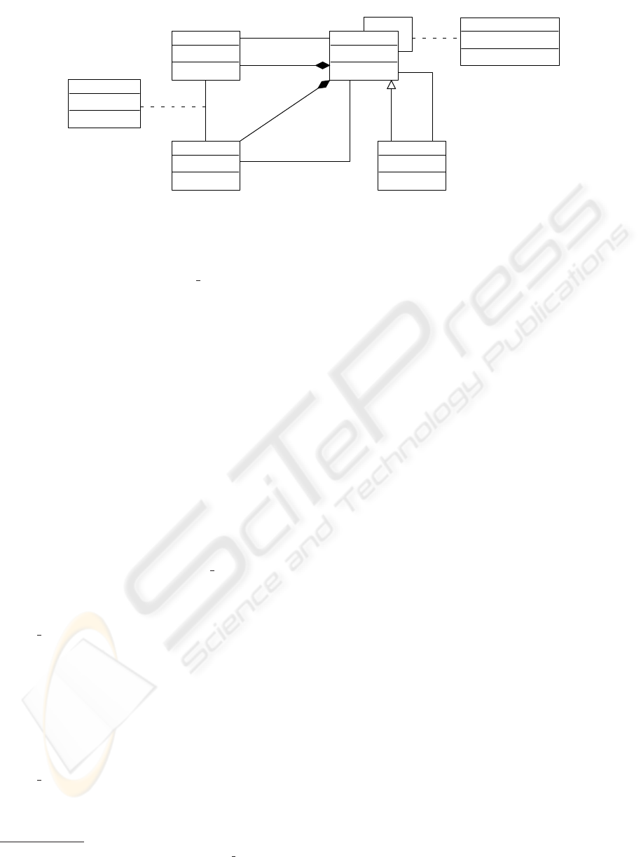
Fig. 4 presents our B meta-model describing the
abstract syntax of commonly used compositional as-
pects in the B method. We consider here only IN-
CLUDES and REFINES links. The other composi-
tion mechanisms (e.g. USES, SEES, etc) can be seen
ICEIS 2008 - International Conference on Enterprise Information Systems
96
BRefinement
BMachine
BData
BOperation
−body:String
used+
*
uses+
*
Access
−Kind:AccessKind
includes+
*
included+
*
Instance_Included
−instance_name:String[0..*]
operations+
*
datadeclare+
data+
*
call+
*
called+
*
refined+
refines+
0..1
refinement
*
*
view
1
OpCall
Figure 4: A meta-model for refinement and composition B structures.
as specializations of the INCLUDES relationship and
they are naturally represented by a reflexive associa-
tion similar to association Instance Included.
In this meta-model, the meta-class BMachine rep-
resents the basic entity in the B method which is the
abstract machine. We consider that a BMachine is
composed by a set of operations (BOperation) and
data (BData). Other constituents of a B machine
(invariants, properties, etc) were discussed in (Idani
et al., 2007). Meta-class BData concerns B variables
and constants. A BOperation in a BMachine uses
B data declared in the same machine following sev-
eral kinds of access (Pre-condition, Reading, Writing,
etc). This is defined by the associative meta-class Ac-
cess.
In B, a refinement is a B machine which refines
another B machine. Thus, meta-class BRefinement in-
herits from BMachine and it is linked to meta-class
BMachine by association refinement (in order to dis-
tinguish refined and refining B machines).
Associative meta-class Instance icluded repre-
sents the inclusion mechanism in the B method.
Roles +includes and +included concern respec-
tively including and included machines. Attribute in-
stance name
2
is given when an including machine in-
cludes one (or several) specific instance(s) of an in-
cluded machine (e.g. instance ThisRoomGate of ma-
chine SecureConferenceAccess).
A B machine can refer (association OpCall) in
its body (in clauses INITIALISATION and OPERA-
TIONS) operations of machines that it includes. Still,
association OpCall between a BOperation O and a
BMachine M is possible only if an association In-
stance Included or refinement exists between M and
the BMachine in which O is defined.
Association view defines a data referencing from
an including BMachine to the included one. The use
2
Multiplicity “[0..*]” of attribute instance name shows
that in an including machine several instance names can be
used for a same B machine, and this name is not mandatory.
of data (relation view) is specified by the visibility
rules of the B theory. Indeed, an including machine
can access data of the machine that it includes only
in reading or through the operations of the included
machine. Thus, specification of B compositions at a
meta-level is rather focused on constraints specific to
meta-classes BMachine, BOperation and BData. For
example, a B machine references data or operations
from other machines only if an inclusion or a refine-
ment link is established.
5 POSSIBLE TRANSLATIONS OF
META-CLASS BMACHINE
Abstract machine is the basic structuring concept of a
B model, its goal is to gather coherentlystatic (B data)
and dynamic (B operations) elements. The decompo-
sition of specifications in several abstract machines is
based on purely logical criteria. In a UML view, such
a structuring is realized by two possible mechanisms:
classes and packages. Thus, we consider these two
point of views when translating the meta-class BMa-
chine. The first point of view (BMachine to Class) al-
lows to see a B machine as a UML class which encap-
sulates attributes(B data) and methods (B operations).
In the second point of view (BMachine to Package), a
B machine is seen as a rather complex entity, whose
constituents (data and operations) can be translated
into well structured model elements (classes, associa-
tions, inheritance, etc). Fig. 5 gives a possible transla-
tion of machine ConferenceRoomGate in which both
class and package point of views are combined.
Note that derivation of class attributes and meth-
ods, stereotypes and relations between the produced
classes were discussed in (Idani et al., 2005). Thus,
this paper doesn’t discuss all derivation rules from B
to UML, but it is focused on translations of composi-
tion links between B machines. We won’t prescribe
a mechanic algorithm for deriving structural views
TOWARDS REVERSE-ENGINEERING OF UML VIEWS FROM STRUCTURED FORMAL DEVELOPMENTS
97
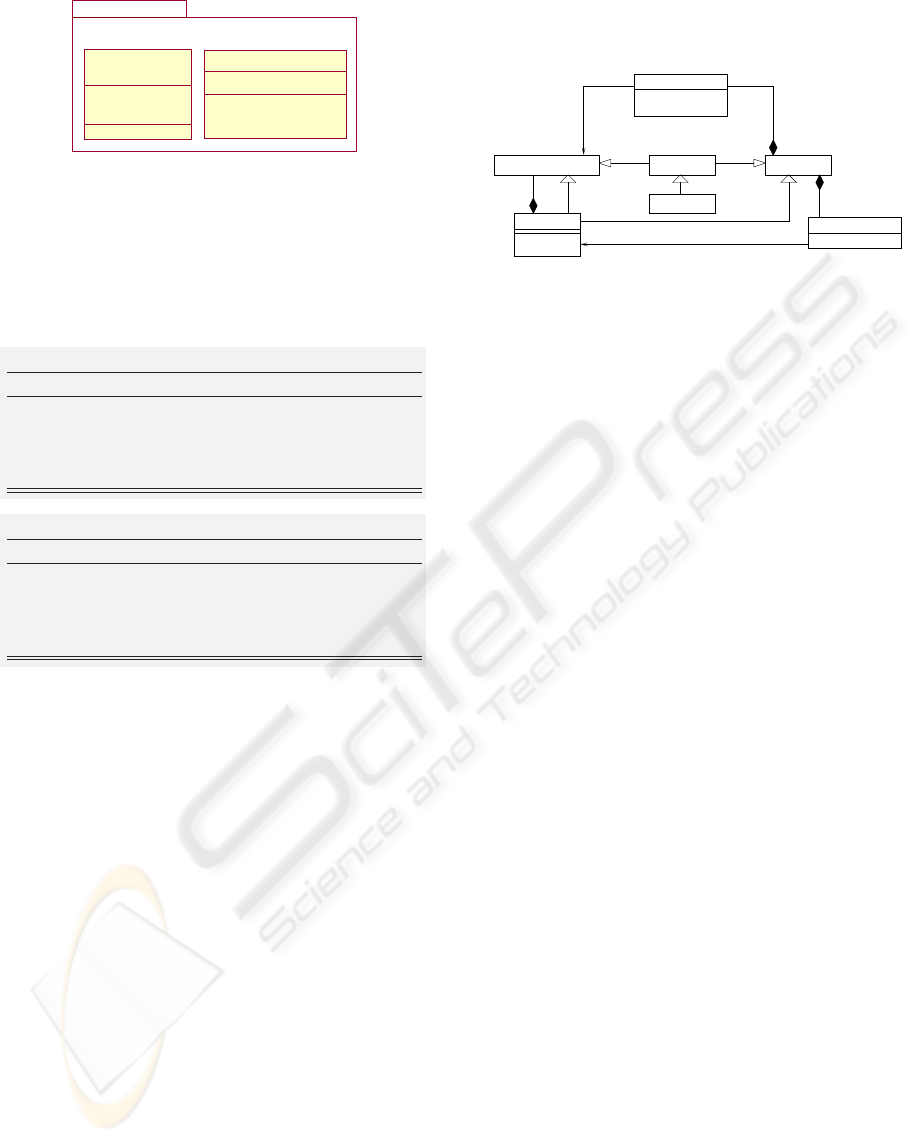
Figure 5: Translation of machine ConferenceRoomGate.
from B specifications. The transformationprocess de-
scribed here is guided by heuristic rules depending
on the appreciation of the analyst. Hence, in order
to treat translations of compositional aspects in the B
method, we propose the following main rules:
Rule 1. (BMachine translation)
Parameters: M : BMachine
Transformation: M is translated into a package
gathering a set of model elements. These pack-
ageable elements come from data (BData) and
operations (BOperation) defined in M .
Rule 2. (BMachine translation)
Parameters: M : BMachine
Transformation: M is translated into a UML
class. The structural and behavioral features of
this class correspond to the data (BData) and op-
erations (BOperation) defined in M .
6 TRANSLATION OF
COMPOSITIONAL ASPECTS
Since a B machine leads to a class or/and a package
according to the selected translation rule, translation
of composition relations (inclusion, refinement, etc)
between B machines depends on possible dependen-
cies between these resulting entities.
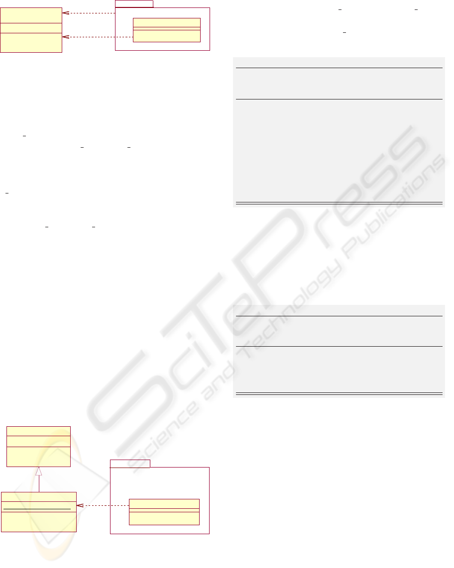
6.1 UML Packages Dependencies
In (Fig. 6) we show a fragment of the UML meta-
model concerned with UML packages. UML pack-
ages dependencies are defined as referencing links
which allow a source package to accede to elements
(said public or visible) of a target package. These
links are specified by meta-classes ElementImport
and PackageImport and indicate a private or public
visibility of the referenced elements (Fig. 6). While
meta-class ElementImport lists elements of the tar-
get package which are specifically referenced by the
source package, meta-class PackageImport covers all
elements of the target package. In both cases, only
members of the target package which have a public
visibility can be referenced.
NameSpaceClassifier
ElementImport
visibility : VisibilityKind
alias : String [0..1]
PackageableElementPackageableElement
PackagePackage
0..1
*+ownedMember
PackageImport
visibility : VisibilityKind
* +packageImport
importedPackage
Class
+elementImport
*
1
1
+importedElement
Figure 6: UML meta-model for package dependencies.
Basically, UML gives two kinds of package de-
pendencies:
• Dependency ≪import≫: indicates a transitive
package dependency; indeed, the import referenc-
ing of several elements of a package P
1
by a pack-
age P
2
is set for a package P
3
which imports P
2
.
• Dependency ≪access≫: means that the pack-
age dependency is not transitive, and the scope of
referenced elements in this case is limited to the
source package of the access referencing.
The portion of UML meta-model given in Fig. 6
allows to distinguish dependencies between classes
and packages. A package is a NameSpace which can
import (+elementImport) a PackageableElement.
This one may be a class (+importedElement) or
a package. Furthermore, a class is a NameSpace
too which can then import (+packageImport)
a package (+importedPackage) or a class
(+importedElement).
6.2 UML Classes Dependencies
Dependenciesbetween UML classes can exist for sev-
eral reasons (Fowler, 2004): one class sends a mes-
sage to another class; some structural features of a
class are stored in another class, one class uses an-
other as a parameter type in one or several of its
methods, etc. In this work, we consider three main
class dependencies: (i) associations (allow to connect
classes), (ii) call of methods (designed by the stereo-
type ≪call≫), and (iii) use of attributes (specified by
stereotype ≪use≫).
6.3 Translation Rules
Let M
1
and M
2
be two B abstract machines (in-
stances of meta-class BMachine). We assume that
a composition link exists from M
1
to M
2
. In the
following, rule 3 and its sub-rules are proposed in
ICEIS 2008 - International Conference on Enterprise Information Systems
98
BData
BMachine
PackageableElementPackageableElement NameSpace
0..1
*+ownedMember
PackagePackage
Element
instance_name : String
Instance
DirectedRelationShip
*
+data
*
*
+includes
+included
PackageImport
visibility : VisibilityKind
* +packageImport
1
importedPackage alias : String
+target
1..*
+source
1..*
Figure 7: Illustration of rule 3.1.
case of an inclusion link (i.e we consider that M
1
includes M
2
).
Rule 3. (INCLUDES clause)
Parameters: M
1
, M
2
: BMachine
Precondition: M
1
includes M
2
Transformation: Execute one of the following
sub-rules.
Considering that for each B machine, rules 1 and 2
(proposed in Sect. 5) produce either a class or a pack-
age, then several configurations must be taken into ac-
count.
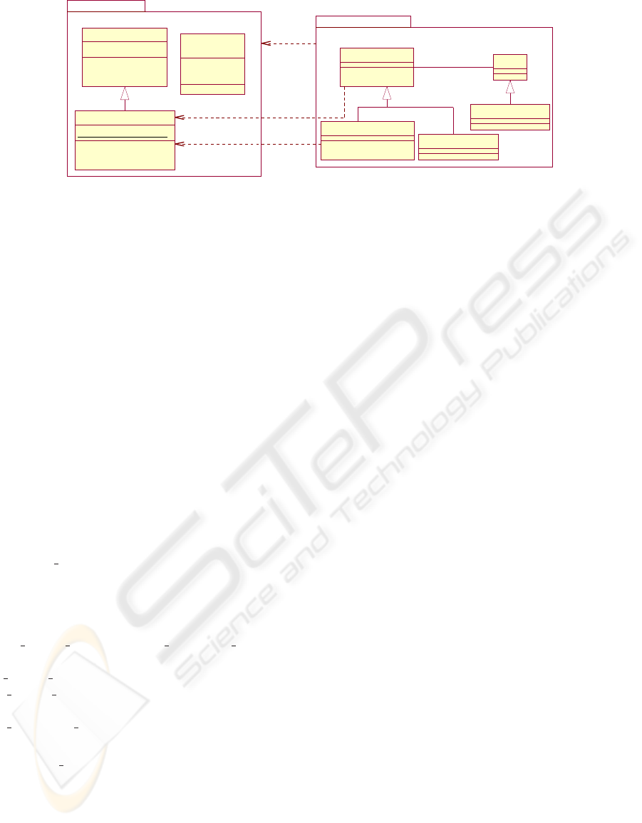
6.3.1 Each BMachine Produces a UML Package
Rule 3.1
Precondition: M
1
: BMachine
Rule
1
−−−→ P
1
: Package
and M
2
: BMachine
Rule
1
−−−→ P
2
: Package
Transformation: The inclusion between M
1
and
M
2
is translated into a dependance link from P
1
to P
2
with the stereotype ≪import≫. The alias
name associated to this import dependance is that
of the instance name of M
2
in M
1
.
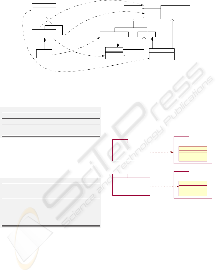
As the INCLUDES clause provides a transitive vis-
ibility mechanism then dependency between result-
ing packages is of type ≪import≫. Fig. 7 high-
lights projections from the proposed B meta-model to
the UML meta-model when including and included
abstract machines are translated into UML packages
(e.g. P
1
and P
2
). In this case we assume that instances
of BData associated to M
1
and M
2
are translated into
packageable model elements packed up in P
1
and P
2
,
and such that elements of P
2
are used (or referenced)
by elements of P
1
.
Rule 3.1. creates an instance of PackageImport
to translate the inclusion mechanism, such that the
source (+source) and the target (+target) of this
instance are respectively P
1
and P
2
. The instance
name of the included machine used in the includ-
ing machine (attribute instance name), becomes a
value of attribute alias in the instance of PackageIm-
port. Finally, the attribute visibility of this instance of
PackageImport is set to public, which corresponds to
stereotype ≪import≫ (Fig. 8).
Figure 8: Possible applications of Rule 3.1.
Dependency ≪import≫ identified by Rule 3.1.
may cover only some elements of P
2
, particularly
those used in the body of M
1
. This is recommended
when package P
2
is quite complex. In this case, the
inclusion mechanism doesn’t lead to an instance of
meta-class PackageImport, but rather to an instance
of meta-class ElementImport. The source model ele-
ment of this instance is the UML package produced
from the including machine while its target is a pack-
aged model element. For example, suppose that ma-
chine ConferenceRoomGate is translated into a pack-
age named P ConferenceRoomGate and containing
class ConferenceRoomGate, the resulting diagrams
are illustrated in Fig. 8.
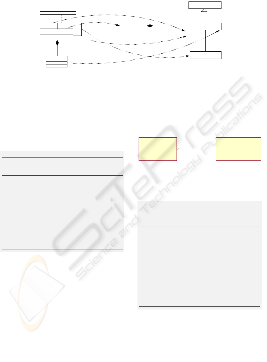
Considering that translation of the INCLUDES
clause into a dependency ≪import≫ is justified by
TOWARDS REVERSE-ENGINEERING OF UML VIEWS FROM STRUCTURED FORMAL DEVELOPMENTS
99
BData
BMachine
StructuralFeature
PropertyClass
Association
instance_name : String
Instance
*
+data
*
*
+includes
+included
0..1 *
+ownedAttribute
+class
2..*
0..1
+memberEnd
+association
Figure 9: Illustration of rule 3.2.
(i) the visibility of model elements of the target pack-
age and (ii) the transitive character of this relation-
ship, then we can consider similar translations of
other B composition clauses. For example, the non-
transitivity of clauses USES and SEES can be reduced
to a dependency ≪access≫ between resulting pack-
ages.
6.3.2 Each BMachine Produces a UML Class
Rule 3.2
Precondition: M
1
: BMachine
Rule
2
−−−→ C
1
: Class
and M
2
: BMachine
Rule
2
−−−→ C
2
: Class
Transformation: Attributes of C
2
corresponding to
BDatas used in clauses PROPERTIES or INVARI-
ANT of M
1
, or referenced in the body of opera-
tions of M
1
become public attributes (thus they
can be used by Class C
1
). The inclusion between
M
1
and M
2
is translated into an unidirectional
association from C
1
to C
2
, such that multiplici-
ties associated to C
1
and C
2
are respectively 0..1
and 1. If an instance name of M
2
is explicitly de-
fined in M
1
then it becomes a role name beside
C
2
. Otherwise, this role name is that of class C
2
.
Fig. 9 highlights projections from the proposed B
meta-model to the UML meta-model when includ-
ing and included abstract machines (M
1
and M
2
) are
translated into UML classes (e.g. C
1
and C
2
). In this
case, we assume that instances of BData and BOp-
eration issued from each machine are translated into
attributes and methods of classes C
1
and C
2
.
For example, if machines SecureConferenceAc-
cess and ConferenceRoomGate are translated into
UML classes, then application of Rule 3.2. builds
diagram of Fig. 10. Attribute state of class Con-
ferenceRoomGate is set to public because variable
state of machine ConferenceRoomGate is referenced
in the invariant of SecureConferenceAccess, and it
is used by operations enter central hall and en-
ter conference room. Methods of class SecureCon-
ferenceAccess can accede to attributes and methods
of class ConferenceRoomGate whereas the reverse is
not allowed. An instance of SecureConferenceAccess
is necessarily linked to a unique ConferenceRoom-
Gate qualified by the role name ThisRoomGate. Fur-
thermore, a ConferenceRoomGate participates to role
ThisRoomGate for at the most one instance of Secure-
ConferenceAccess.
Figure 10: Application of Rule 3.2.
6.3.3 M
1
is Translated into a Package and M
2
is
Translated into a Class
Rule 3.3
Precondition: M
1
: BMachine
Rule
1
−−−→ P : Package
and M
2
: BMachine
Rule
2
−−−→ C : Class
Transformation: Attributes of C corresponding to
BDatas used in clauses PROPERTIES or INVARI-
ANT of M
1
, or referenced in the body of opera-
tions of M
1
become public attributes. The ma-
chine inclusion is translated into a dependency
≪import≫ from P to C . The alias name asso-
ciated to this import dependancy is that of the in-
stance name of M
2
in M
1
. Classes of P are linked
to class C by dependencies ≪use≫ or ≪call≫
according to a use of attributes or a call of op-
erations of C . Finally, stereotype ≪utility≫ is
added to C .
In this case we consider that on the one hand, BDatas
issued from M
1
are translated into model elements
gathered in package P , and on the other hand, BDatas
issued from M
2
are translated into attributes of a
UML class C .
Rule 3.3. builds several kinds of dependency
between P and C . In this translation, class C is
a utility class to ensure that there is a unique set
ICEIS 2008 - International Conference on Enterprise Information Systems
100
!
Figure 11: Application of Rule 3.3.
of data and services accessible by all classes of P .
Fig. 11 presents an example of application of Rule
3.3. In this diagram, we consider that the abstract
set Person is translated into a UML class in pack-
age P SecureConferenceAccess and that it encapsu-
lates operation enter conference room.
Class ConferenceRoomGate acts as a mod-
ule sharing global variables and procedures
which are accessible by classes of package
P SecureConferenceAccess. In UML, this mecha-
nism is represented by the stereotype ≪utility≫.
The pre-condition access of variable state in oper-
ation enter conference room is translated into the
dependency link ≪use≫.
Using the Design Pattern Singleton. The unique-
ness of data and services showed by stereotype
≪utility≫ can be represented more precisely by the
design pattern “Singleton” (Gamma et al., 1995). In-
deed, it ensures that a class has only one instance and
it provides a single point of access to this particular
instance. We can then use the Singleton design pat-
tern to allow classes of package P to share the single
instance of C . In the inclusion mechanism of the B
method, operations of an including machine accede to
specific instances of the included machine. For exam-
ple, operations of SecureConferenceAccess have ac-
cess to the instance ThisRoomGate of machine Con-
ferenceRoomGate.
!!
Figure 12: Application of design pattern “Singleton”.
To illustrate the application of the design pattern
Singleton on our case study we keep the translation of
SecureConferenceAccess into a package containing
the class Person. In the class diagram of Fig. 12,
class ThisRoomGate is a specialization of class
ConferenceRoomGate, as a result it inherits attribute
state and methods open gate() and close gate().
Application of design pattern “Singleton” ensures
that elements of package P SecureConferenceAccess
accede to a unique instance of ThisRoomGate.
Rule 3.4
Precondition: M
1
: BMachine
Rule
1
−−−→ P : Package
and M
2
: BMachine
Rule
2
−−−→ C : Class
Transformation: Attributes of C corresponding to
BDatas used in clauses PROPERTIES or INVARI-
ANT of M
1
, or referenced in the body of opera-
tions of M
1
become public attributes. The ma-
chine inclusion is translated into a class “Single-
ton” which is a sub-class of class C . Classes of
P are linked to class “Singleton” by dependen-
cies ≪use≫ or ≪call≫ according to a use of
attributes or a call of operations of C .
6.3.4 M
1
is Translated into a Class and M
2
is
Translated into a Package
In this case we consider that BDatas issued from M
1
are translated into attributes of a UML class C , and
those of M
2
are translated into packaged model ele-
ments gathered in a package P .
Rule 3.5
Precondition: M
1
: BMachine
Rule
2
−−−→ C : Class
and M
2
: BMachine
Rule
1
−−−→ P : Package
Transformation: The machine inclusion is trans-
lated into a dependency ≪import≫ from C to P
such that instance name of M
2
in M
1
is used as
an alias name.
Translation Rule 3.5 is similar to Rule 3.1. De-
pendency ≪import≫ produced by this rule allows to
the UML class issued from M
1
to accede to elements
of the UML package issued from M
2
.
7 DISCUSSION
Rules proposed in this paper show that many trans-
lations are possible for the composition concept of
the B method. They are then carried out interactively
and may be applied simultaneously by the analyst in
order to produce the most pertinent structural view.
Each abstract machine which compose our case study
can be translated into a class or a package depending
on the application of rules 1 and 2. We believe that
the choice amongst these two translation rules can
be guided by the degree of detail and complexity of
BDatas issued from each B machine. For example, a
TOWARDS REVERSE-ENGINEERING OF UML VIEWS FROM STRUCTURED FORMAL DEVELOPMENTS
101
!!""
#$%
&'
( $%
' &
!!""
!!""
!!""
Figure 13: Application of the proposed rules on our case study.
B machine which consists of several abstract sets and
relations between these sets can be viewed as a pack-
age gathering a set of classes and associations. Identi-
fication of the granularity degree depends on the way
that the analyst specifies B models. Rigorous met-
rics and heuristics can be approached in order to help
use the best rules. This opens a new interesting per-
spective to our contribution. However, this paper is
intended to propose a palette of possible translations
depending from these two main rules.
7.1 Application
Fig. 13 shows a possible application of our transla-
tion rules on the example of Sect. 3.2. In this dia-
gram machine SecureConferenceAccess is translated
into a UML package by applying rule 1, while ma-
chine ConferenceRoomGate is translated into a pack-
age and a class by applying simultaneously rules 1
and 2.
Package P SecureConferenceAccess. It is a rather
complex package gathering several classes and re-
lations. Abstract sets are translated into classes,
relations into associations, and set inclusion pro-
duces inheritance between classes. Operations
enter central hall and enter conference room are
encapsulated respectively by classes Person and
In central hall for the following reasons: (i) en-
ter central hall acts on persons to allow their ac-
cess to the central hall of the building; and (ii) en-
ter conference room concerns only persons who are
in the central hall.
Package P ConferenceRoomGate. In this pack-
age the enumerated set GateStatus becomes an
≪enumeration≫ class, variable state becomes an at-
tribute of class ConferenceRoomGate and operations
of machine ConferenceRoomGate are encapsulated
by its corresponding class.
Links between Packages. In order to translate the
INCLUDES link between machines of our example
we considered the rules 3.1 and 3.4. Rule 3.1 is
justified by the fact that both machines are trans-
lated into UML packages. As a result, a dependency
≪import≫ is created between these packages with
the alias name ThisRoomGate. Rule 3.4 is applied
because machine ConferenceRoomGate is translated
into a UML class and also because machine inclusion
in this case specifies a unique instance of Conference-
RoomGate called ThisRoomGate.
7.2 Existing Works and Contribution
Derivation of UML diagrams from B specifications
could be built using two kinds of tools:
1. Tools that extract the static aspects of the B speci-
fications. For example (Tatibouet et al., 2002) de-
fined some rules to automatically derive a UML
class diagram from formal B specifications. In
the same context, (Fekih et al., 2006) presents
some heuristics which lead to interactively con-
struct simpler diagrams.
2. Tools that represent the behaviour of the specifi-
cations in form of state/transition diagrams. For
example, (Bert and Cave, 2000) starts from a
user-guided choice of significant states and ap-
plies proof techniques to explore all the valid
transitions of the system. In (Leuschel and
Butler, 2003) a model checker of B specifica-
tions is presented. This tool produces concrete
state/transition diagrams where states are valu-
ations of B variables and transitions are opera-
tion calls. Our contribution in this context (Idani
and Ledru, 2006) combines animation and proof
to produce abstract state/transition diagrams more
intuitive and readable.
This paper studied the first kind of tools which
extract a UML structural view from existing formal
specifications. It is the first attempt for reverse-
engineering of UML diagrams from composition
clauses of the B method. Indeed, existing works in-
cluding our previous contribution (Idani and Ledru,
2006; Idani et al., 2005) deal with specifications built
by a unique B machine.
ICEIS 2008 - International Conference on Enterprise Information Systems
102

8 CONCLUSIONS
A crucial idea of Model Driven Engineering is that
transformations between heterogeneous models can
be described uniformly in terms of meta-model map-
pings. Based on the fact that meta-models define an
abstract syntax from which one can describe model
semantics, transformation rules that arise from MDA-
based techniques are explicit and precise.
In our contribution we applied such a technique
in order to address the reverse-engineering of UML
structural diagrams from formal B specifications of
information systems. Derivation rules are described
in an MDA framework in terms of projections from
a proposed B meta-model to the UML meta-model.
Currently, we are working on integrating efficiently
the proposed extensions to our MDA-based CASE
tool for combining UML and B notations. The tool
is intended, on the one hand, to circumvent the lack
of traceability of UML-to-B approaches, and on the
other hand, to provide a useful UML documentation
of B developments in order to help understanding for-
mal specifications. Still, further research is needed to
broaden the scope of our method and its support tool
and cover more B constructs (e.g. refinements, etc).
Another interesting perspective is to integrate to our
tool a checker which allows to apply transformations
only if the B specifications are neither redundant nor
inconsistent among them. The intention of such a B
specifications checker is to avoid derivation of incor-
rect UML diagrams.
Bridging the gap between UML and B notations
have received a lot of interest in the last decade
from the scientific community. However existing ap-
proches were not applied on large-scale applications.
Experimentsdone by our tool (Idaniet al., 2005) (pre-
sented in Sect. 2) showed encouraging results in this
direction, and the approach presented in this paper
provides a better coverage of B and UML.
REFERENCES
Abrial, J.-R. (1996). The B-book: assigning programs to
meanings. Cambridge University Press.
Abrial, J.-R. (1999). System study: Method and exam-
ple. http://www-lsr.imag.fr/B/Documents/ClearSy-
CaseStudies/.
Behm, P., Benoit, P., Faivre, A., and Meynadier, J.-M.
(1999). METEOR: A successful application of B in a
large project. In FM’99, volume 1709 of LNCS, pages
369–387. Springer-Verlag.
Bert, D. and Cave, F. (2000). Construction of Finite La-
belled Transition Systems from B Abstract Systems.
In Integrated Formal Methods, volume 1945 of LNCS,
pages 235–254. Springer-Verlag.
Fekih, H., Jemni, L., and Merz, S. (2006). Transforma-
tion of B Specifications into UML Class Diagrams and
State Machines. In 21st Annual ACM Symposium on
Applied Computing, pages 1840–1844. ACM.
Fowler, M. (2004). UML 2.0. CampusPress.
Gamma, E., Helm, R., Johnson, R., and Vlissides, J. (1995).
Design patterns: elements of reusable object-oriented
software. Addison-Wesley Professional.
Idani, A. (2006). B/UML: Mise en relation de sp´ecifications
B et de descriptions UML pour l’aide `a la validation
externe de d´eveloppements formels en B. PhD thesis,
Universit´e de Grenoble - France.
Idani, A., Boulanger, J.-L., and Philippe, L. (2007). A
generic process and its tool support towards combin-
ing UML and B for safety critical systems. In 20th
Int. Conf. on Computer Applications in Industry and
Engineering, pages 185–192, USA.
Idani, A. and Ledru, Y. (2006). Dynamic Graphical
UML Views from Formal B Specifications. Interna-
tional Journal of Information and Software Technol-
ogy, 48(3):154–169. Elsevier.
Idani, A., Ledru, Y., and Bert, D. (2005). Derivation of
UML Class Diagrams as Static Views of Formal B
Developments. In International Conference on For-
mal Engineering Methods (ICFEM’05), volume 3785
of LNCS, pages 37–51, UK. Springer-Verlag.
Laleau, R. and Polack, F. (2002). Coming and Going from
UML to B: A Proposal to Support Traceability in Rig-
orous IS Development. In B’02, volume 2272 of
LNCS, pages 517–534. Springer.
Lano, K., Clark, D., and Androutsopoulos, K. (2004). UML
to B: Formal Verification of Object-Oriented Models.
In Integrated Formal Methods, volume 2999 of LNCS,
pages 187–206. Springer.
Leuschel, M. and Butler, M. (2003). ProB: A Model
Checker for B. In FME 2003: Formal Meth-
ods Europe, volume 2805 of LNCS, pages 855–874.
Springer-Verlag.
Sekerinski, E. (1998). Graphical Design of Reactive Sys-
tems. In B’98, pages 182–197, London, UK. Springer.
Snook, C. and Butler, M. (2006). UML-B: Formal mod-
eling and design aided by UML. ACM Transactions
on Software Engineering and Methodology (TOSEM),
15(1):92–122.
Tatibouet, B., Hammad, A., and Voisinet, J. (2002). From
an abstract B specification to UML class diagrams.
In 2nd IEEE International Symposium on Signal Pro-
cessing and Information Technology.
TOWARDS REVERSE-ENGINEERING OF UML VIEWS FROM STRUCTURED FORMAL DEVELOPMENTS
103
