
A VISUAL SPECIFICATION TOOL FOR
EVENT-CONDITION-ACTION RULES SUPPORTING
WEB-BASED DISTRIBUTED SYSTEM
Wei Liu, Ying Qiao, Xiang Li
Institute of Software, Chinese Acedemy of Sciences, No. 4 Zhong Guan Cun South Fourth Street, Beijing, China
Kang Zhong, Hongan Wang, Guozhong Dai
Institute of Software, Chinese Acedemy of Sciences, No. 4 Zhong Guan Cun South Fourth Street, Beijing, China
Keywords: Event-condition-action Rules, Active Database, Visual Specification tool, XML, Compile.
Abstract: Specifying Event-Condition-Action (ECA) rules is an important issue in the domain of active database.
Current specification tools for ECA rules include visual specification tools and textual specification tools
based on XML. Here, the visualization of ECA rules provides an easy-to-use interface in design/analysis
tools for active database queries while the XML-based representation allows the exchange of ECA rules in a
web-based distributed environment. Thus, a specification tool with advantages of both visual representation
and XML-based representation is needed. In this paper we present and implement a new visual specification
tool for ECA rules, called VSTE, to address this issue. We also use a web-based smart home system to
evaluate our work.
1 INTRODUCTION
Event-condition-action (ECA) rules play very
important roles in active databases since they define
how active databases perform corresponding actions
to response to the data and events. Visual languages
have been considered to be good tools to specify
ECA rules since they use the synthesis power of the
eye (Matskin, 1996) and hide the irrelevant details
behind users so as to make human understanding
and following of rule execution and triggering easier.
Several visual ECA rule languages have been
presented in active database area. Some of them are
based on the visualization of rules in modelling
diagrams such as class diagrams (Calestam, 1999),
state-chart diagrams (Berndtsson, 2003), ER
diagrams (Navathe, 1992), or specific rule
diagrams(Silva, 1996). Others are based on
visualization of how rules behave and interact with
each other and the underlying data model at run-time
(Wagner, 2003).
Meanwhile, in web-based distributed
environment, ECA rules need to be exchanged
between different applications and platforms.
However, none of current visual specification
tools/languages can support this kind of exchange of
ECA rules. This makes applications on one site
unable to understand graphical ECA rules specified
on different sites.
In recent years, several ECA rule specification
languages based on the form of XML have been
presented to support the exchange of ECA rules
between different applications and platforms (Boley,
2002, Cho, 2002, Seirio, 2005). However, this brings
another problem: compared to visual ECA rule
languages, textual specification languages are
difficult to reveal structures of rules and follow the
triggering relationship between rules. This hinders
human understandings whereas to increase
difficulties in rule execution and rule checking.
Therefore, the issue for combining the
visualization of ECA rules and the XML-based
representation as a single tool needs to be addressed
in the domain of active databases and this paper
presents an implemented solution.
The main idea of our solution is to compile
visual ECA rules into XML to deal with the
heterogeneity of ECA rules in web-based distributed
environment. Specifically, we present and
246
Liu W., Qiao Y., Li X., Zhong K., Wang H. and Dai G. (2008).
A VISUAL SPECIFICATION TOOL FOR EVENT-CONDITION-ACTION RULES SUPPORTING WEB-BASED DISTRIBUTED SYSTEM.
In Proceedings of the Tenth International Conference on Enterprise Information Systems - DISI, pages 246-251
DOI: 10.5220/0001700102460251
Copyright
c
SciTePress
implement a new visual specification tool for ECA
rules, called VSTE. The core of this tool is a visual
ECA rule language, called VECAS. It has a
compatible syntax structure with XML. Once the
user specifies ECA rules with VSTE, the graphical
representations of VECAS will be automatically
transformed in the form of XML in the background.
The rest of the paper is organized as follows:
section 2 addresses a visual specification language
for ECA rules, called VECAS; section 3 addresses
the implementation of compiler; section 4 evaluates
VSTE via a web-based smart home system.
Conclusions and future works are stated in section 5.
2 VISUAL SPECIFICATION
LANGUAGE
2.1 Modeling
The model behind the language constructs of
VECAS can be represented as an augmented graph:
))(),(,,( EMVAttrEVG =
(1)
V is a set of vertices. V= V
E
∪ V
C
∪ V
A
, where V
E
is a set of event vertices, V
C
is a set of condition
vertices and V
A
is a set of action vertices. Each
element in these three sets represents an event, a
condition and an action respectively. The details of
the events, conditions and actions supported by
VECAS can be found in (Qiao, 2007) and are
skipped due to size limit.
E is a set of edges. Each edge is a connection
between different types of vertices. VECAS supports
following three types of connections: EC
connection (The relationship between an event and a
condition; It means that once the event is detected,
the condition will be examined.), CA connection
(The link between a condition and an action; It
means that once the condition is examined to be
satisfied, the action will be executed.) and RR
connection (The triggering relationship between two
ECA rules; It means that execution of one rule may
trigger execution of another.).
Attr(V) is a set of attributes applied to each
vertex to describe its critical characteristics. The
attribute sets of each type of event, condition and
action are addressed in (Qiao, 2007) and are skipped
in this paper.
M(E) is a set of constraints on each edge. It
describes the characteristics of each connection.
These constraints represent coupling modes between
events, conditions and actions (Paton, 1993).
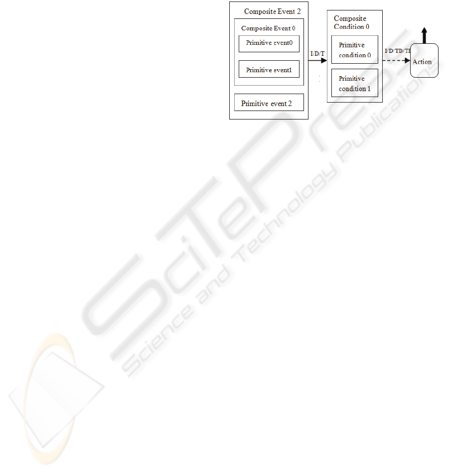
2.2 Syntax Structure
Based on the model addressed in section 2.1, the
syntax of VECAS can be graphically represented as
Figure 1.
Figure 1: Syntax of VECAS.
In Figure 1, an event/condition is graphically
represented by a square associated with a set of
attributes. A single square is used for a primitive
event/condition while nested squares are used for a
composite event/condition. An action is represented
as a rounded rectangle associated with
corresponding attributes. The detailed graphical
notations for events, conditions and actions can be
found in our previous work (Qiao, 2007) and are
skipped since they are not the emphases for this
paper. The EC connection is graphically represented
as a line with an arrow. The symbols “I”, “D” and
“T” are constraints on the EC connection. They
represent three coupling modes (Paton, 1993)
between an event and a condition. The CA
connection is graphically represented as a dash with
an arrow. The symbols “I”, “D”, “TD” and “TI” are
constraints imposed on the CA connection. They
represent four coupling modes (Paton, 1993)
between a condition and an action. Furthermore, the
RR connection is graphically represented as a bold
line with an arrow.
2.3 Editing Environment
VSTE provides a graphical rule editor for users to
define ECA rules with VECAS. The Graphical User
Interface (GUI)of the rule editor is shown in
Figure 2.
A VISUAL SPECIFICATION TOOL FOR EVENT-CONDITION-ACTION RULES SUPPORTING WEB-BASED
DISTRIBUTED SYSTEM
247
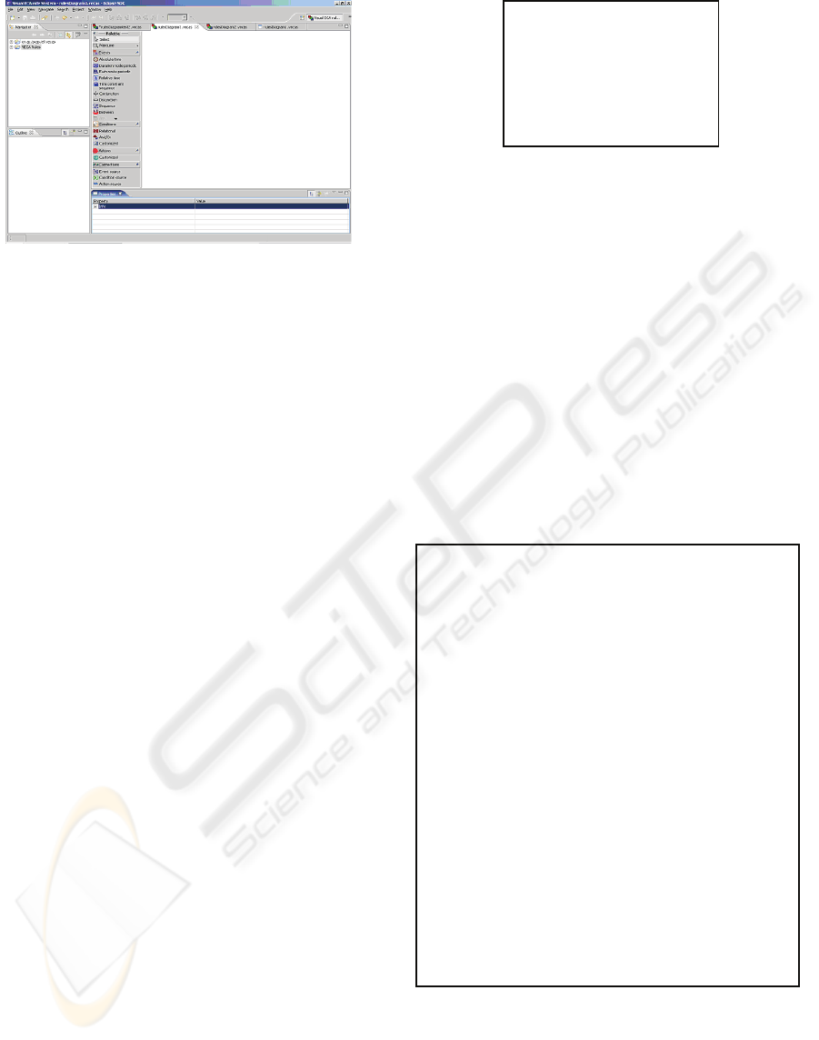
Figure 2: GUI for editing ECA rules.
The GUI includes four areas, i.e., navigator area,
outline area, rule edit area, and property define area.
In the navigator area, the name of project and the
files contained in this project are listed. When the
user defines a group of rules, a project containing
several files is created. A group of dependent rules
are saved into one file under this project. The outline
area is responsible to display the overall picture of
selected group of ECA rules defined by the user. A
set of graphical components is provided in the rule
edit area. Users can drag corresponding graphical
components into the edit area to draw ECA rules
according to the syntax of VECAS addressed in
section 2.2. There are four types of graphical
components, i.e., event components, condition
components, action components and connection
components. The detailed graphical notations for
each graphical component can be found in our
previous work (Qiao, 2007). In the property defining
area, the user can define the attributes associated
with each graphical block in defined ECA rules.
3 COMPILER
Compiler is a key infrastructure of VSTE, which is
responsible to convert VECAS representations of
ECA rules into corresponding XML-based
representations. Via the compiling, a corresponding
XML file is created for VECAS codes of a specific
set of dependent ECA rules. This XML file has a
root element. The name of the root is defined as
“VECAS” indicating the file is compiled from
VECAS codes. There are two main sections in the
file, i.e., Module section and Rule section. The
Module section is used to define reused elements in
XML descriptions. The Rule section is used to
define a set of dependent ECA rules. The framework
of this XML file is shown in Figure 3.
Figure 3: Framework of compiled XML file.
The core of a compiler is a mapping mechanism
which is used to create the Rule section in the
compiled XML file. It includes two aspects, i.e.,
component mapping and attribute mapping.
In component mapping, the compiler identifies
each single ECA rule among a group of dependent
graphical ECA rules and creates a sub-element
called “ruleitem” for each identified ECA rule in the
Rule section. Then, the compiler will search all
graphical blocks in each ECA rule and convert
graphical blocks representing events, conditions and
actions into corresponding event sub-element,
condition sub-element and action sub-element of
each “ruleitem” element. Figure 4 shows the
framework of the Rule section in a compiled XML
file created via the component mapping.
Figure 4: Framework of Rule section.
In attribute mapping, the compiler examines
attributes associated with each graphical block in a
graphical ECA rule and maps them into the
attributes with the same names for corresponding
event sub-element, condition sub-element and action
<VECAS>
<module>
…
</module>
<Rules>
…
</Rules>
</VECAS>
<Rules>
<Rule>
<Ruleitem name=”yyy”; priority=1;executable= True>
<event>
…
</event>
<condition>
…
</condition>
<action>
…
</action>
</Ruleitem>
</Rule>
<Rule>
<Ruleitem name=”zzz”; priority=2; executable= True>
<event>
…
</event>
<condition>
…
</condition>
<action>
…
</action>
</Ruleitem>
</Rule>
/R l
Navigation
area
Outline
area
Rule edi
t
area
Property defining area
ICEIS 2008 - International Conference on Enterprise Information Systems
248
sub-element of a “ruleitem” element in the Rule
section.
4 CASE STUDY
Smart home is the home environment that can
proactively change to provide services that promote
independent living (Augusto, 2005). Assume a web-
based smart home system has two local smart home
systems S1 and S2. Each computer-based smart
home system consists of a group of sensors and an
active database. In this context, a group of sensors
are used to collect the data about the person’s
movements throughout the house, the status of
person’s health and the various home appliances and
facilities. These data are sent to an active database
which holds a set of ECA rules. With ECA rules, the
active database has the enhanced capabilities to
detect complex events and contexts in order to
anticipate potential or actual hazardous situations
and intelligently discern how to best advise medical
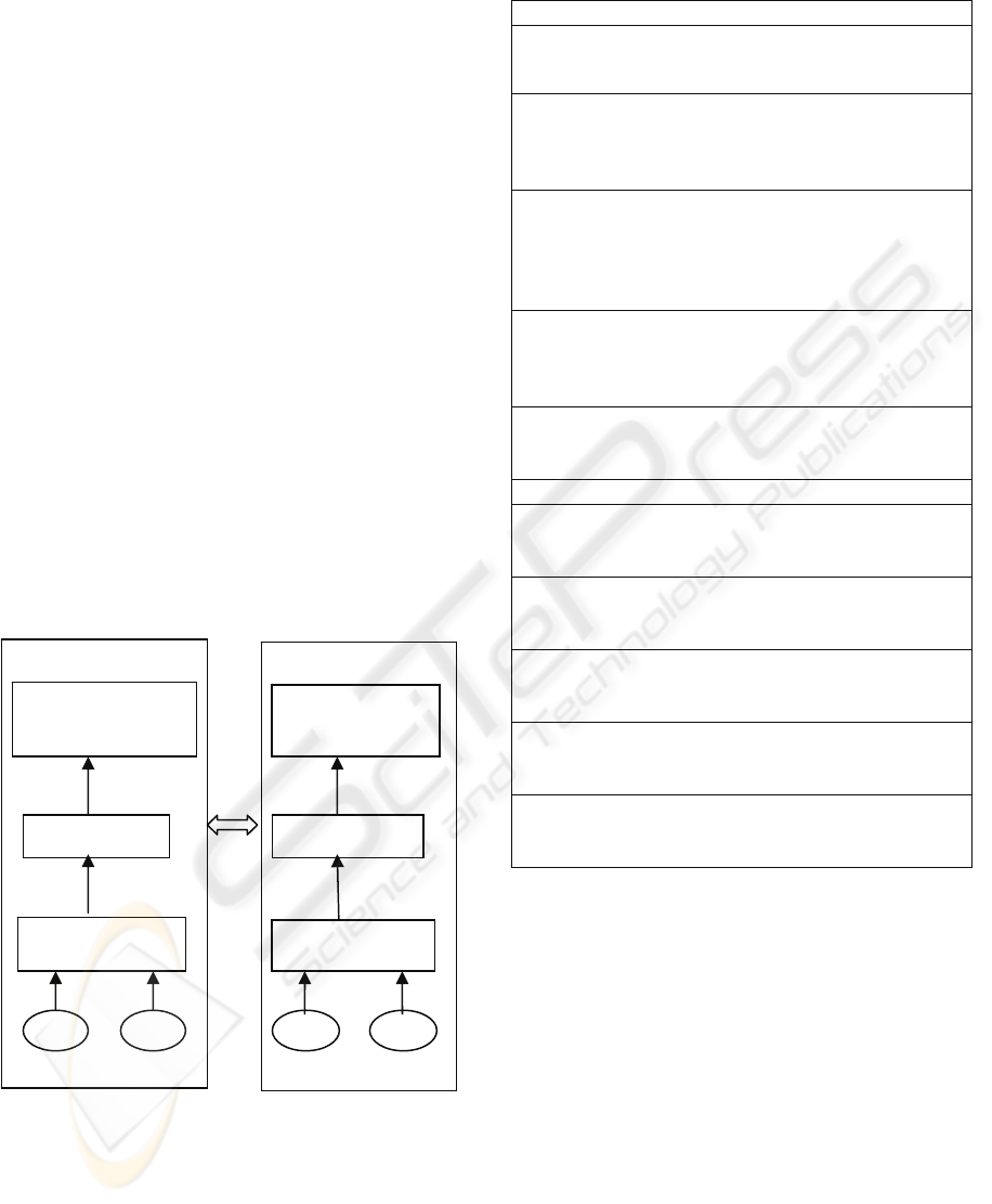
staffs. Figure 5 shows the architecture of the web-
based smart home system. The detailed requirements
for ECA rules in local smart home system S1 and S2
are shown in Table 1.
Figure 5: Architecture of web-based smart home system.
Table 1: Requirements for ECA rules.
ECA rules in S1
Req1: On “At 10:00AM”
If “the person’s blood pressure is higher than 200/175”
Do “Notify the medical staff”
Req2: On “ Monitor blood pressure every 2 hours”
If “ the Blood pressure higher than 200/175 for more
than two times in past 8 hours”
Do “Notify the medical staff”
Req3: On “the person is in bed during [T1, T2]”
If “ the person is active during [D1, D2]” and “[T1, T2]
is included in [D1, D2] and “Duration [T1, T2] is
longer than 2 hours”
Do “Report the context abnormal”
Req4: On “ Monitor blood pressure every 2 hours” and “blood
pressure higher than 200/175 for more than two
successive samples”
Do “
Notify the medical staff”
Req5: On “ Blood pressure higher than 200/175” after “the
heart beat is higher than 150” within 5 minutes
Do “ Notify the medical staff
”
ECA rules in S2
Req6: On “1 hour after the cooker is on”
If “the cooker is still on”
Do “Trigger alarm”
Req7: On “ 15 minutes after the door is open”
If “the door is still not locked”
Do “Trigger alarm”
Req8: On “1 minutes after leaving the bath room”
If “the light leaving on” or “the water leaving on”
Do “Create a reminder”
Req9: On “ the person does not pass” after “the door is open”
during [12:00Am, 7:00AM]
Do “ Create remin
der”
Req10: On “leaving a room”
If “monitored key is on the desk”
Do “trigger alarm process”
To evaluate VSTE’s capability to support the
exchange of ECA rules, we use VSTE and four
typical visual specification tools for ECA rules, i.e.
OMT-A(Calestam, 1999), UML-A(Berndtsson,
2003), ECA
2
nets(Navathe, 1992) and
A/OODBMT(Silva, 1996) to specify the ECA rules
in local smart home system S1 and S2 based on the
requirements in Table 1 and analyze if the system S1
and S2 can access each other’s ECA rules in
different cases of visual specification tool usages.
Table 2 gives evaluation results. (Here, we do not
show the detailed graphical representations of ECA
rules specified by VSTE and four selected visual
specification tools since they are not emphases for
the evaluations.)
Decision on
notification
Application A
Active Database 1
Sensor Sensor
Cell phone/special
devices of medical
staff
S1
Site A
Decision on
notification
Application B
Active Database 2
Sensor Sensor
Cell phone/special
devices of medical
staff
S2
Site B
A VISUAL SPECIFICATION TOOL FOR EVENT-CONDITION-ACTION RULES SUPPORTING WEB-BASED
DISTRIBUTED SYSTEM
249
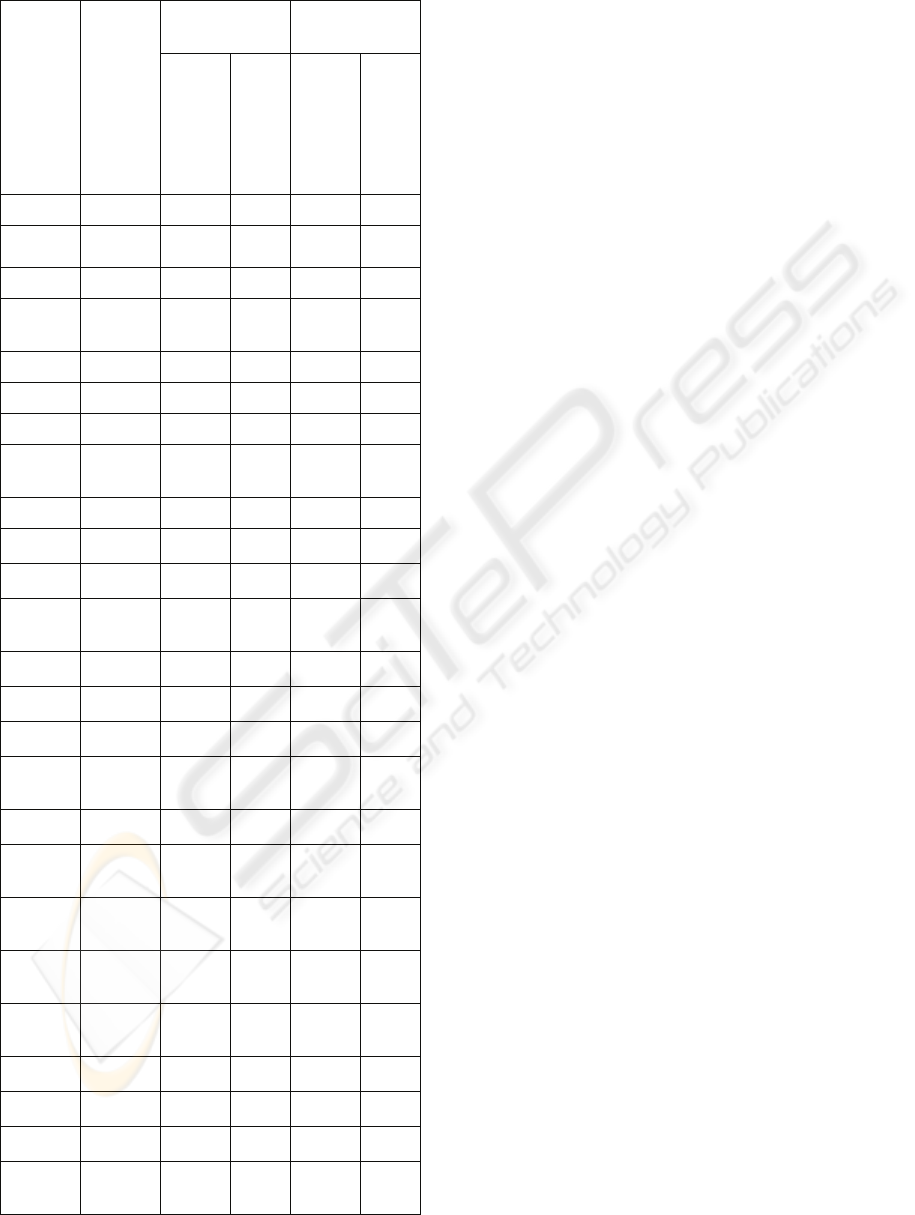
Table 2: Evaluation results.
Same platforms Different
platforms
Visual
specific
ation
tool
used by
S1
Visual
specific
ation
tool
used by
S2
S1
access
ECA
rules
in S2
S2
acces
s
ECA
rules
in S1
S1
access
ECA
rules
in S2
S2
access
ECA
rules
in S1
OMT-A OMT-A Yes Yes No No
UML-A UML-A Yes Yes No No
ECA
2
ECA
2
Yes Yes No No
A/OOD
BMT
A/OOD
BMT
Yes Yes No No
VSTE VSTE Yes Yes Yes Yes
OMT-A UML-A No No No No
OMT-A ECA
2
No No No No
OMT-A A/OOD
BMT
No No No No
OMT-A VSTE Yes No Yes No
UML-A OMT-A No No No No
UML-A ECA
2
No No No No
UML-A A/OOD
BMT
No No No No
UML-A VSTE Yes No Yes No
ECA
2
OMT-A No No No No
ECA
2
UML-A No No No No
ECA
2
A/OOD
BMT
No No No No
ECA
2
VSTE Yes No Yes No
A/OOD
BMT
OMT-A No No No No
A/OOD
BMT
UML-A No No No No
A/OOD
BMT
ECA
2
No No No No
A/OOD
BMT
VSTE Yes No Yes No
VSTE OMT-A No Yes No Yes
VSTE UML-A No Yes No Yes
VSTE ECA
2
No Yes No Yes
VSTE A/OOD
BMT
No Yes No Yes
From Table 2, we can observe four cases:
• Case 1: When system S1 and S2 have same
platforms and they use same visual specification
tools, they can access each other’s ECA rules and
the exchange of ECA rules is allowed.
• Case 2: When system S1 and S2 have same
platforms and they use different visual specification
tools, there are following three sub-cases:
(1) When S1 and S2 use different selected visual
specification tools, they cannot access each
other’s ECA rules and the exchange of ECA
rules is not allowed.
(2) When S1 uses one of selected visual
specification tools and S2 uses VSTE, the
exchange of ECA rules is not allowed. In this
case, S1 can access ECA rules in S2, but S2
cannot access ECA rules in S1.
(3) When S1 uses VSTE and S2 uses one of
selected visual specification tools, the
exchange of ECA rules is not allowed. In this
case, S2 can access ECA rules in S1, but S1
cannot access ECA rules in S2.
• Case 3: When system S1 and S2 have different
platforms but they use same visual specification
tools, there are following two sub-cases:
(1) When S1 and S2 use selected visual
specification tools, they cannot access each
other’s ECA rules and the exchange of ECA
rules is not allowed.
(2) When S1 and S2 use VSTE, they can access
each other’s ECA rules and the exchange of
ECA rules is allowed.
• Case 4: When system S1 and S2 have different
platforms and they use different visual specification
tools, there are following three sub-cases:
(1) When S1 and S2 use different selected visual
specification tools, they cannot access each
other’s ECA rules and the exchange of ECA
rules is not allowed.
(2) When S1 uses one of selected visual
specification tools and S2 uses VSTE, the
exchange of ECA rules is not allowed. In this
case, S1 can access ECA rules in S2, but S2
cannot access ECA rules in S1.
(3) When S1 uses VSTE and S2 uses one of
selected visual specification tools, the
exchange of ECA rules is not allowed. In this
case, S2 can access ECA rules in S1, but S1
cannot access ECA rules in S2.
Here, Case 1 is rare since the local smart home
systems are usually independently developed before
they are connected to create a web-based smart
home system. Case2, Case 3 and Case 4 are very
popular for a web-based smart home system. Thus,
ICEIS 2008 - International Conference on Enterprise Information Systems
250

based on above analysis, we can make following
conclusions:
(1) Compared to current typical visual
specification tools, our specification tool
VSTE has much stronger capability to
support the exchange of ECA rules in web-
based distributed environment.
(2) In web-based distributed environment, the
exchange of ECA rules between different
applications and platforms can be achieved
when the active databases in local systems
use our specification tool VSTE to specify
their ECA rules.
5 CONCLUSIONS
Although many works have been done on visual
specification tools for ECA rules, none of them is
able to support the exchange of ECA rules in web-
based distributed environment. Meanwhile, textual
specification tools based on XML provide an
efficient way to deal with the exchange of ECA rules
between different applications and platforms.
However, these textual specification tools are hard
to be used by the user who lacks of professional
skills. To solve above problems, we integrate
visualization of ECA rules and the XML-based
representation as a single tool by developing a new
visual specification tool for ECA rules called VSTE.
It provides a visual specification language for users
to specify ECA rules and the defined graphical
representations can be automatically converted into
the form of XML, which makes ECA rule
specifications suitable to support the exchange of
ECA rules between different platforms and
applications. Furthermore, we use a web-based
smart home system to evaluate our work. The
evaluation results show that compared to selected
visual specification tools, VSTE has much stronger
capability to support the exchange of ECA rules in
web-based distributed environment.
ACKNOWLEDGEMENTS
This work is supported by France Telecom (Grant
No. 46135653) and Hi-tech Research and
Development Program of China (Grant No.
2006AA042182).
REFERENCES
Matskin, M, Montesi, D., 1996. Visual Rule Language for
Active Database Modeling. Available at :
http://citeseer.ist.psu.edu/32316.html.
Calestam, B., 1999. OMT-A: An Extension of OMT to
Model Active Rules. In MS dissertation HS-IDA-MD-
99-001. Department of Computer Science, University
of Skovde, Sweden.
Berndtsson, M., Calestam, B., 2003. Graphical Notations
for Active Rules in UML and UML-A. In ACM
SIGSOFG Software Engineering Notes, 28:2. ACM
Press.
Navathe, S.B., Tanaka, A. K., Chakravarthy, S., 1992.
Active Database Modeling and Design Tools: Issues,
Approach and Architecture. In IEEE Quarterly
Bulletin on Data Engineering, Special Issue on Active
Database, 15(1-4): 6-9. IEEE Press.
Silva, M.J.V., Carlson, C.R., 1996. Conceptual Design of
Active Object-Oriented Database Applications Using
Multi-level Diagrams. In ECCOP’96, 10
th
European
Conference on Object-Oriented Programming,
Volume 1098 of Lecture Notes in Computer Science,
pp.366-397. Springer.
Wagner, G., 2003. The Agent-object-Relationship Meta-
Model: Towards a Unified View of State and
Behavior. In Information Systems, 28:5, pp.475-504.
Elsevier Press.
Cho, E., Hyun, S., 2002. ARML: Active Rule Markup
Language for Sharing Rules among Active
Information Management Systems. In First
International Workshop on RuleML.
Boley, H., Grosof, B., Sintek, M., Tabet, S., Wanger, G.
2002. RuleML Design. RuleML initiative, available at:
http://www.ruleml.org.
Seirio, M., Berndtsson, M., 2005. Design and
Implementation of an ECA rule Markup Language. In
International Conference on Rules and Rule Markup
Languages for the Semantic Web and OWL Workshop.
Qiao, Y., Zhong, K., Wang, H., Li, X., 2007. Developing
Event-condition-action Rules in Real-time Active
Database. In ACM symposium on applied computing,
pp. 511-516. ACM Press.
Paton, N., Diaz, O., Williams, M., 1993. Dimensions of
Active Behavior. In the 1st International Workshop on
Rules in Database Systems, pp. 40-57.
Augusto, J., Nugent, C., 2004. A New Architecture for
Smart Homes Based on ADB and Temporal
Reasoning. In ICOST2004, 2
nd
International
Conference on Smart Homes and Health Telematic,
Assistive Technology Research Series, Volume 14,
pp.106-113. IOS Press.
A VISUAL SPECIFICATION TOOL FOR EVENT-CONDITION-ACTION RULES SUPPORTING WEB-BASED
DISTRIBUTED SYSTEM
251
