
MUICSER: A MULTI-DISCIPLINARY USER-CENTERED
SOFTWARE ENGINEERING PROCESS TO INCREASE THE
OVERAL USER EXPERIENCE
Mieke Haesen, Kris Luyten, Karin Coninx, Jan Van den Bergh and Chris Raymaekers
Hasselt University - tUL - IBBT, Expertise Centre for Digital Media, Wetenschapspark 2, B-3590 Diepenbeek, Belgium
Keywords:
User-Centered Design, Software Engineering, Model-Driven.
Abstract:
In this paper we present an incremental and user-centered process to create suitable and usable user interfaces.
Validation is done throughout the process by prototyping, the prototypes evolve from low-fidelity to the final
user interface. Applications developed with this process are more likely to correspond to users’ expectations.
Furthermore, the process takes into account the need for sustainable evolution often required by modern soft-
ware configurations, by combining traditional software engineering with a user-centered approach. We think
our approach is beneficial in its scope, since it considers evolving software beyond the deployment stage and
supports a multi-disciplinary team.
1 INTRODUCTION
In this contribution we present an overall approach for
the (re-)design of interactive applications that takes
into account the needs of the end-user as well as the
needs of the designer and developer. Our approach
can be used to design new applications that require in-
put from many different sources (e.g. domain experts)
or even to redesign legacy applications to improve the
user experience they offer. This approach builds on
existing models and notations in both the software
engineering and human-computer interaction (HCI)
community, providing extensions where necessary.
Based on our experiences and observations when
working with multi-disciplinary teams, we are gradu-
ally introducing an agile model-based approach in ap-
plied research and software development projects. We
will be using different models throughout the process,
where each model describes a specific aspect of an in-
teractive system and represents the viewpoint of one
or more specific roles in the multi-disciplinary team.
User-Centered Design (UCD) approaches are
meant to support the development process in such
a way that software quality attributes like usability
and overall compliance to the user needs are taken
into account. Therefore, combining a model-driven
approach and a user-centered development process
seems a natural way to ensure benefits for the end-
user as well as the development team. The arti-
facts created using the proposed user-centered devel-
opment cycle contribute to well-considered and trace-
able design decisions. The need for communication
with end-users or customers results in additional mod-
els or artifacts (e.g. low-fidelity and high-fidelity
prototypes) on top of the commonly used models
in a model-driven approach, which are very helpful
to support the communication in a multi-disciplinary
project team (e.g. task model, presentation model
etc.).
In this paper, we present a user-centered software
engineering proces and detail the models and artifacts
that are at the center of the approach. A discussion of
our current and future work, as well as related work,
conclusions are presented.
2 MuiCSer
Our Multi-disciplinary user-Centered Software
engineering process, MuiCSer, embodies UCD
with a structured Agile Software Engineering
(ASE)((Larman, 2003)) process. Figure 1 gives an
overview of the proposed process. At first this may
seem as a waterfall type of process model. However,
the development team can choose which stages are
tackled during one timeboxed iteration. At the end
of each iteration, there will be artifacts which can be
of various types (e.g. low-fidelity prototypes, UML
diagrams, executable code,. . . ) and will be stored in
371
Haesen M., Luyten K., Coninx K., Van den Bergh J. and Raymaekers C. (2008).
MUICSER: A MULTI-DISCIPLINARY USER-CENTERED SOFTWARE ENGINEERING PROCESS TO INCREASE THE OVERAL USER EXPERIENCE.
In Proceedings of the Tenth International Conference on Enterprise Information Systems - HCI, pages 371-374
DOI: 10.5220/0001707303710374
Copyright
c
SciTePress
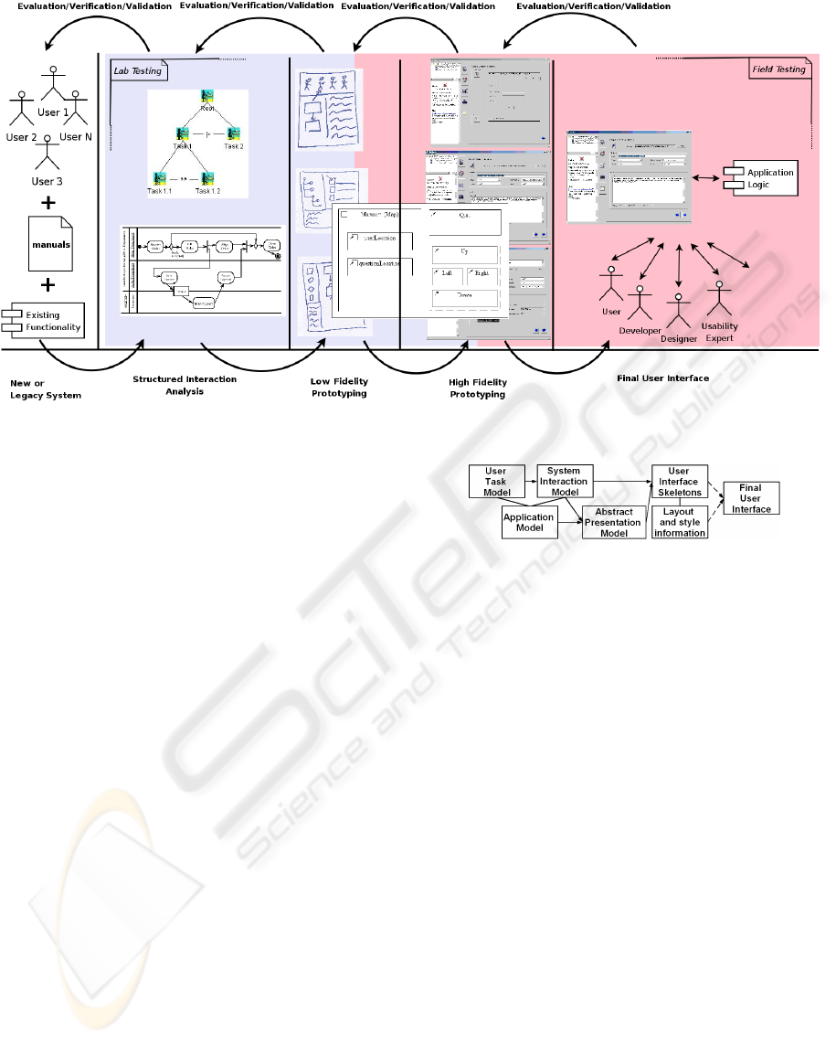
Figure 1: The MuiCSer Process.
a central repository ready for use in the next iteration.
The next paragraphs discuss the properties of the
process we propose in more detail.
The process typically starts with an analysis phase
in an initial iteration where the users tasks, goals and
the related objects or resources that are important to
perform these tasks are specified. If the user experi-
ence of a legacy system needs to be optimized, the
functionality of such a system can be often found
in existing manuals thus it can also contribute to the
analysis.
During the structured interaction analysis, the re-
sults of the first stage are used to progress towards
system interaction models and presentation models.
These models are often expressed using the UML no-
tation, thus being kept in pace with the traditional SE
models.
Since both user needs and functional information
are specified, they can serve as input for the low fi-
delity prototyping stage. User interface designers cre-
ate mockups of the user interface, based on the in-
formation contained in the task and interaction mod-
els, while using design guidelines and their experi-
ence. In subsequent phases, we go from low-fidelity
to high-fidelity prototypes, which on their turn evolve
into the concrete user interfaces. So each stage grad-
ually evolves towards the final user interface, but is
still related to the artifacts created in a previous stage.
An overview of the artifacts involved can be seen
in Figure 2. It shows the artifacts created or updated
during the design and the relations between them.
By evaluating the result of each stage, the support
Figure 2: Artifacts created during the design process.
for user needs and goals and the presence of required
functionality is verified. If possible, an evaluation
with target users can be very useful to get feedback
from the end user directly. Because most of the ar-
tifacts do not present a fully functional system, part
of the testing takes place in a usability lab. To evalu-
ate some advanced prototypes, field tests can examine
the user interface in more realistic situations. If the
results of a phase are too complex to involve an end
user during evaluation, it is still necessary to evaluate,
verify or validate the models or prototypes.
MuiCSer as depicted in Figure 1 shows only one
iteration (or increment) in the development of the
complete system. The back arrows at the upper side
of the figure emphasize that one can iterate over the
previous phase, depending on the results of the evalu-
ation of the current artifact.
3 HCI ENGINEERING MODELS
The proposed notations are built on existing model
notations used in software engineering and interface
design and specification. The following sections de-
scribe different models being created, changed and
transformed during the execution of the process in or-
ICEIS 2008 - International Conference on Enterprise Information Systems
372

der to support a smooth transfer towards the final user
interface. These models and their interrelations are
shown in the left part of Figure 2.
3.1 The User Task Model
User task models specify requirements for an appli-
cation from a users’s point of view, in a hierarchical
way. We use the ConcurTaskTrees (CTT) notation
(Mori et al., 2002) in the second stage of MuiCSer. It
has proven to be easy to understand and usable, even
for complex systems. In our previous work, we in-
dicated that working prototypes with inter- and intra-
dialog navigation can be generated by combining this
notation with high-level user interface descriptions
(Luyten et al., 2003).
Van den Bergh and Coninx (Van den Bergh and
Coninx, 2006) showed a correspondence between the
CTT notations and UML 2.0 activity diagrams. This
mapping results in the system interaction model as de-
scribed in section 3.3.
3.2 The Application Model
The application model is traditionally used to describe
the objects and commands provided by the applica-
tion logic. The model is represented using the UML
class diagrams and can be considered most closely
related to the data or object model. The application
model is useful to describe the interface between the
user interface and the application logic.
Furthermore, the application model is an impor-
tant model for legacy systems, since the application
logic is already available when the design of a (new)
user interface starts.
3.3 The System Interaction Model
The system interaction model offers a system-centric
description of action flows that can be performed by
the system, by a user through the system, or that
have an influence on the system. The model is ex-
pressed using UML 2.0 activity diagrams, extended
with new stereotypes corresponding to the task types
in the CTT notation.
3.4 Abstract Presentation Model
The abstract presentation model defines the structure
of the user interface in a platform independent man-
ner describing the logical and temporal structure of
the user interface through a hierarchy of abstract in-
teraction components. The model is expressed using
the UML class diagram, in which each component is
represented by a stereotyped class
1
.
A complete formal mapping to the Canonical Ab-
stract Prototypes (CAP) (L. Constantine, 2003) is not
possible due to the informal semantics, rudimentary
rules were however identified. The notation will be
used as a front-end for a designer to add additional
information, such as screen organization.
In MuiCSer, we employ high-level user interface
descriptions to define the high-fidelity prototype. We
prefer UIML (Luyten and Coninx, ) and XForms (Van
den Bergh et al., 2007) to render the prototypes, but
other user interface description languages are also
possible. These languages should be XML-based and
independent of the application logic, to smooth the
transformation between prototypes and the final user
interface.
4 ONGOING AND FUTURE
WORK
The process presented in this paper has been tested on
software projects of limited complexity and, by con-
sequence, with a development team of limited size.
Although our tests did not include any larger soft-
ware projects, the process should be flexible enough
to support the increased complexity and team size.
One of our main contributions is that different do-
main experts can use their own notations to create
models which can relate to models of other domain
experts, in order to obtain a complete and usable in-
teractive system with respect to the requirements. We
are testing this approach in different application do-
mains (applications for logistics, community websites
etc.), requiring different experts to collaborate.
We plan to gradually improve the relation between
the different types of artifacts, which is a key fac-
tor for success. The combination of HCI models
and UML models guarantees a smooth integration of
the user interface and application logic. Putting for-
ward the combination of models explicitly also pre-
vents mismatches between the functionality provided
by the application logic and the functionality accessi-
ble through the user interface.
5 RELATED WORK
This paper is not the first to look into the relation be-
tween user-centered design and both HCI and soft-
1
Stereotypes (Object Management Group, 2004) are
standardized means to extend the UML language.
MuiCSer: A MULTI-DISCIPLINARY USER-CENTERED SOFTWARE ENGINEERING PROCESS TO INCREASE
THE OVERAL USER EXPERIENCE
373

ware engineering models. Hudson (Hudson, 2004)
describes a way to use UML in combination with
user-centered design, but does not address how user
interfaces can explicitly be modeled in UML.
A study on the state of UCD by Mao et al. (Mao
et al., 2005) showed among other things that although
many parts of UCD are practiced in actual develop-
ment in industry, end-to-end deployments are seldom
due to limitations of current practice.
Wisdom (Nunes, 2001) defines a set of models
using the standard UML-diagrams and stereotypes
to create more appropriate notations for a variety of
models that can be used to design interactive systems
in small teams. Wisdom also provides a user-centered
methodology to effectively use the notation.
Campos et al. (Campos and Nunes, 2005) pro-
posed a workstyle model, Galactic Dimensions, that
focuses on workstyle transitions rather than a design
process. The workstyle model allows to evaluate tools
according to different dimensions that characterize
different workstyles.
6 CONCLUSIONS
In this paper we introduced a novel process, prac-
ticing User-Centered Software Engineering in such
ways that methodologies used by developers as well
as the creativity of designers are included and a posi-
tive user experience is more likely to be obtained. Al-
though both HCI and Software Engineering models
are integrated into one process, it is up to the multi-
disciplinary project team which models will be used.
To provide even more flexibility, we also included ex-
plicit support for legacy systems being updated or ex-
tended.
Whenever possible, an evaluation with end users
is recommended in each step. However since end
users are not always available or should not under-
stand all models, validation or verification by the
project team is suggested. This approach also encour-
ages the development of software in several iterations
and increments.
ACKNOWLEDGEMENTS
Part of the research at EDM is funded by the
ERDF (European Regional Development Fund) and
the Flemish Government. The VIP-lab project
(4-BMG-II-2=37), is financed by the “Interreg
Benelux-Middengebied” authorities and co-financed
by Province of Limburg (B), Province of Limburg
(NL), Ministry of Economic Affairs (NL) and Min-
istry of Flemish Government/Economic Affairs (B).
The MuiCSer process is also based on our ex-
periences in IWT projects Participate (with Alcatel-
Lucent) and AMAS++ (IWT 060051).
REFERENCES
Campos, P. F. and Nunes, N. J. (2005). Galactic Dimen-
sions: a Unifying Workstyle Model for User-Centered
Design. In INTERACT’05, volume 3585 of LNCS,
pages 158–169. Springer.
Hudson, W. (2004). Object Modeling and User Inter-
face Design, chapter Toward Unified Models in User-
Centered and Object-Oriented Design, pages 313 –
362. Addison Wesley.
L. Constantine, L. (2003). Canonical abstract prototypes for
abstract visual and interaction design. In Proc. DSV-IS
2003, volume 2844 of LNCS, pages 1–15. Springer.
Larman, C. (2003). Agile and Iterative Development: A
Manager’s Guide. Addison-Wesley.
Luyten, K., Clerckx, T., Coninx, K., and Vanderdonckt, J.
(2003). Derivation of a Dialog Model from a Task
Model by Activity Chain Extraction. In Proc. DSV-IS
2003, volume 2844 of LNCS, pages 203–217.
Luyten, K. and Coninx, K. Uiml.net: an open uiml renderer
for the .net framework. pages 257–268.
Mao, J.-Y., Vredenburg, K., Smith, P. W., and Carey, T.
(2005). The state of user-centered design practice.
Communications of the ACM, 48(3):105–109.
Mori, G., Patern
`
o, F., and Santoro, C. (2002). CTTE: sup-
port for developing and analyzing task models for in-
teractive system design. IEEE Transactions on Soft-
ware Engineering, 28(8):797–813.
Nunes, N. J. (2001). Object Modeling for User-Centered
Development and User Interface Design: The Wisdom
Approach. PhD thesis, Univ. da Madeira.
Object Management Group (2004). UML 2.0 Superstruc-
ture Specification.
Van den Bergh, J. and Coninx, K. (2006). Cup 2.0: High-
level modeling of context-sensitive interactive appli-
cations. In Proc. MoDELS 2006, volume 4199 of
LNCS, pages 140–154.
Van den Bergh, J., Huypens, S., and Coninx, K. (2007). To-
wards Model-Driven Development of Staged Partici-
patory Multimedia Events. In Proc. DSV-IS, volume
4323 of LNCS, pages 81–94.
ICEIS 2008 - International Conference on Enterprise Information Systems
374
