
WALKTHROUGH METHODS FOR IMPROVING THE SYSTEM
FIT TO THE USERS’ TASKS WITHIN MANUFACTURING
OPERATIONS
Taru Salmimaa, Inka Vilpola and Katri Terho
Department of Information Technology, Tampere University of Technology, Tampere, Finland
Keywords: Walkthrough method, paper prototype, scenarios, user involvement, requirement specification, evaluation.
Abstract: Designing an information system for manufacturing context has challenges, such as efficiency and user
requirements. Therefore manufacturing systems should be evaluated with real users before their
implementation. The purpose of the evaluation is to ensure that a system supports the work flows and that
users are introduced to a new system in the early stages of design. Walkthrough methods provide means to
simultaneously review a sequence of actions and involve the users in the design activities. In this paper, a
pluralistic walkthrough method was used for evaluating a user interface of a manufacturing system. In the
session, the target user groups performed predefined task scenarios with a paper prototype of the system.
The results indicate that walkthrough methods could be applicable for the manufacturing systems design,
and the results could improve the system design and the user acceptance.
1 INTRODUCTION
Manufacturing contexts present several challenges
for systems design, such as allocation of users’ tasks
and functionality of technology. In order a system to
be efficient and purposeful, the internal logic and the
external compatibility must be ensured already in
design phase. First the system has to support the
work flows of users, and second the users have to
accept and use the system. If these conditions are not
fulfilled, the system becomes useless.
Walkthrough methods are utilized for different
purposes, e.g. code review, business process review
or user interface evaluation. The methods vary in
their objectives, purpose and participants.
Walkthrough methods usually require preparative
actions like data gathering, modelling and designing
a solution that is then evaluated in a walkthrough
session. However, they provide an efficient and
intensive way to achieve shared understanding
among stakeholders, e.g. designers, users and their
managers. Moreover they help to detect problems of
the design before implementation phase.
In this paper, three walkthrough methods,
Participatory heuristic evaluation (Muller et al.
1998), Pluralistic walkthrough (Bias 1991), and
Socio-technical walkthrough (Hermann et al. 2004),
are first introduced in terms of their objective,
purpose and participants needed. Then a detailed
case example of how to conduct a pluralistic
walkthrough session in a manufacturing context is
described. Finally the applicability of walkthrough
methods in manufacturing controlling systems
design is discussed and conclusions are drawn.
2 WALKTHROUGH METHODS
The primary criterion for selecting a walkthrough
method to be applied is the objective of the
walkthrough. Table 1 provides criteria for the
selection of the previously introduced methods.
Participatory heuristic evaluation is best suited
for inspecting interface design in a detailed level
taking into account the process in which the system
is used.
380
Salmimaa T., Vilpola I. and Terho K. (2008).
WALKTHROUGH METHODS FOR IMPROVING THE SYSTEM FIT TO THE USERS’ TASKS WITHIN MANUFACTURING OPERATIONS.
In Proceedings of the Tenth International Conference on Enterprise Information Systems - HCI, pages 380-383
DOI: 10.5220/0001709803800383
Copyright
c
SciTePress
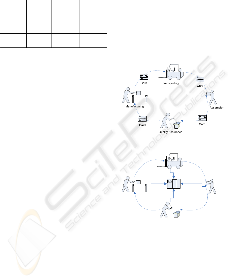
Table 1: Selection criteria for a walkthrough method.
Methods Objective Purpose Participants
Participatory
heuristic
evaluation
Interface,
process
scenarios
Evaluation Experts and
users
Pluralistic
walkthrough
Interface,
scenarios
Evaluation,
design
Experts,
designers and
users
Socio-
technical
walkthrough
Process,
system
Design,
evaluation
Experts,
designers and
users
Pluralistic walkthrough is on a higher level of
abstraction and concentrates on how the interface
responds to the work flows in terms of scenarios.
Socio-technical walkthrough on the other hand
concentrates on the interaction between the social
and technical system in the work process. Even
though interface of the technical system might be
involved, the focus is more on the work process. The
purpose of the walkthrough is usually evaluation,
but it always provides input to design. In pluralistic
walkthrough the design may be updated in the
walkthrough session, because of the presence of
designers. In socio-technical walkthrough the design
function is in even greater role. The participation of
different roles in each of the methods is seen in the
table. Expert refers to a human factors specialist.
3 APPLYING THE PLURALISTIC
WALKTHROUGH METHOD TO
THE SYSTEM DESIGN
The case study approach is suitable for exploring the
phenomena within a limited group or organisation
(Yin 1992). The aim of this case study is to explore
what kind of benefits and limitations occurs when a
walkthrough method is used in the design of the
manufacturing control system.
3.1 The Design of the Manufacturing
Control System
The current manual manufacturing system included
moving physical objects i.e. cards from operator to
another (Fig.1). The cards cotrolled the production,
for example notified that the assembler had
consumed the material produced by the
manufacturer. The problems with the manual cards
were e.g. lost cards, inaccurate timing, and that
participant could not see the status of one another’s
work in real time.
Therefore, a manufacturing system was to be
designed. The desired manufacturing control system
is an information system that replaces the current
cards (Fig. 2) The system tackles the problems with
manual cards, and moreover has controlling
functions such as production priorities and
calculation of the material needed for current
production.. The desired system also increases the
visibility of the production process (Fig. 2) that also
changes the social environment in a way that
operators are able to see the status of the whole
process.
Figure 1: An illustration of the current manual system in
use.
Figure 2: An illustration of the desired manufacturing
control system in use.
The overall designing process of this system is
presented by Salmimaa and Vilpola (2007), but the
focus in here is limited to the walkthrough session
and its contribution to the design. Also the
practicalities of how to conduct a walktrough session
are revealed in this case.
3.2 The Walkthrough Session
During the pluralistic walkthrough session, each
primary user i.e. operator (Fig. 3) worked as a
Assembler
Manufacturing
Transporting
Quality Assurance
y
y
y
Manufacturing Control System
WALKTHROUGH METHODS FOR IMPROVING THE SYSTEM FIT TO THE USERS’ TASKS WITHIN
MANUFACTURING OPERATIONS
381
partner with some other primary user or with a
human factor professional or a designer. The
partners representing different aspects were expected
to create more versatile comments on the
functionality, the scenarios and the UI design. Each
scenario was presented on first the slide show and
walked through with the paper prototype. The
responsible role that also performed the task in real
context, had an opportunity to start commenting.
Other users could comment afterwards.
The paper prototypes are based on the predefined
task sequences created from the notes of the
observations in the real context of use. In this case,
with the aid of the walkthrough session, the system
functionality can be double-checked with the end
users, because the paper prototypes and scenario
descriptions work as a stimulus for the participants.
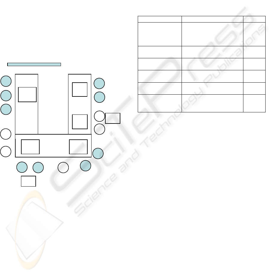
Figure 3: The seats of the participants and the location of
the paper prototypes in the room.
The paper prototypes were distributed to the
participants, one for several participants As
designed so far, every user should have own device
but only few users have hand terminal (MPP in Fig.
3) in the shop floor. The amount of hand terminals
were kept limited for a purpose that the real situation
can be simulated.
Fast moving steps on the user interfaces were
presented by using power point slide shows (Figure
3). Thus, the simulation was quite close to reality.
Also the comments from the participants can be
captured on the paper prototype UIs to appropriate
locations. The developers may browse through the
corrections before illustrating the UI sketches into
the requirement specification. Most of the
development ideas collected in the session
concerned improvements on UIs.
3.3 Results
The table 2 presents the user roles and use scenarios
that have been gone through in more detail in the
walkthrough session.
Table 2: User roles and Use scenarios with the number of
the notes emerged during the walkthrough session.
User Scenarios Notes
Operator A in the
component line
1. Booking a material and
a product type for
preparing the components
at the line.
4
Operator B in the
component line
2. Registration at the
intermediate storage
2
Truck driver 3. Transporting units on
the truck
2
Production
controller
4. Updating the product
information
2
All Users 5. Registration of a
defective product
3
Production
manager
6. Updating the
manufacturing order list at
the component line
2
The development ideas emerged mostly at the first
use case “Booking a material and a product prepared
for preparing the component at the line” (Table 2).
The list of works designed for Operator A was quite
usable and simple to use from users’ standpoint.
Some corrections are needed, e.g. how to present the
highest priority on the list. Also some additional
information was missing on the view, e.g. product
information on the manufacturing order list.
The consensus among the participants prevailed
in terms of the main view in which the status of the
whole production process and demand of a critical
component should be presented. General comments
on the feedback or error messages presented on the
screen were raised up by some operators and system
developers. Concerning the location information of
the truck, the updating in any case (also overwriting)
has to be possible.
Trolleys, which are used for moving the material in
the process, without any identification label have to
be registered into the system in some way because
these are not registered into the system at all. Each
trolley in the system needed to be identified and
traced. The identification needs to be double-
checked. If the server of the system is fallen down,
the trolleys have to be taken an inventory. The most
important thing is that the production is not
D
O
O
O
O
O
O
O
O
P
PT
P
D
R
PP
PP
CPP
MPP
Æ Slide shows of the use
PT= Project Team
O= Operator
D= Designer
R=Researcher
PP= Paper
Prototype
MPP= Mobile
Paper Prototype
PP PP
MPP
ICEIS 2008 - International Conference on Enterprise Information Systems
382

interrupted if the system would be down. The status
view and logs have to be maintained. The production
parameters have to be easily modified.
Defective product can be easily returned to the
production. The location information of the
defective product is very important so that it can be
transported as soon as possible to the unburden area.
There are several reasons for the defective products.
In the current manual system, the operator has to call
to a team responsible person before implying the
defective product. Some discussions have emerged
from the reasons for the failures on the process.
Breakdowns occur in the process. Thus, the
messages about the breakdowns have to be
registered to the system in real-time in order to share
the information in the whole process. A responsible
primary user argued that they need as accurate
information about the consuming rate of units as
possible. It is a significant trigger to the component
line and should be updated in real-time to the
system. The assembly machine can also register the
information about each unit running in the machine.
4 CONCLUSIONS
Manufacturing control systems are designed
according to the manufacturing logic of increasing
company productivity. Designing such a system
includes planning how the system will support the
tasks of end users. In this paper, a pluralistic
walkthrough method is used for evaluating a system
design from users’ perspective. The primary users,
e.g. the main operators in the system, were using a
paper prototype of the system according to
predefined scenarios of use. As a result their
comments were considered for the requirement
specification of the system.
Walkthrough methods provide an intensive way
to “walk through” the functionality of system
design, and iterate the design solution at the early
stage of the design process. Thus, the requirements
for system functionality can be verified before any
function is implemented. Moreover, using
walkthrough methods in the design phase may ease
the adoption stage as the users’ are already
introduced to the system.
The system designers may not be fully aware of the
everyday possibilities and practical restrictions, such
as breakdowns or product changes. The
communication ability between designers and users
help to avoid misunderstandings of the design
objectives.
Organisational change issues, such as job
redesign and changes of the individuals’ tasks, may
pose a threat to shop floor level workers. However,
in the walkthrough session the workers conduct their
tasks with the prototype of the new system.
Therefore, the workers are able to experience how
the new system will affect their work flows. The
issues that are raised during the session can be taken
into account also in the training plan for the new
system. The user acceptance and user satisfaction
are hard to measure, but users’ understanding of the
benefits of the system for their work can be clarified
in the walkthrough session.
The results of this paper affect the requirement
analysis and design process of the manufacturing
control system. In addition the walkthrough session
allowed communication between users and
designers, and introduced the users to the new
system in the early stages of design process.
REFERENCES
Bias, R., 1991. Interface-Walkthroughs: Efficient
Collaborative Testing. IEEE Software, Vol. 8, No. 5,
pp. 94-95.
Bias R., 1994. The Pluralistic Usability Walkthrough:
Coordinated Empathies, in Nielsen J. and Mack R. L
(Eds) Usability Inspection Methods. New York: Wiley
& Sons Inc.
Hermann, T., Kunau G., Loser K., Menold N., 2004.
‘Socio-Technical Walkthrough: Designing technology
along Work Processes’, Proceedings of the eighth
conference on Participatory design: Artful integration:
interweaving media, materials and practices - Volume
1, Participatory Design, Toronto, Ontario, Canada,
July 27-31, 2004, New York, NY, United States, ACM
Press, pp. 132-141.
Muller M. J., Matheson L., Page C., Gallup R., 1998.
Methods & tools: Participatory heuristic evaluation.
Interactions. Vol. 5, No. 5, pp. 13-18.
Nielsen J., 1994. Heuristic Evaluation, in Nielsen J. and
Mack R. L (Eds) Usability Inspection Methods. New
York: Wiley & Sons Inc.
Salmimaa, T., Vilpola, I., 2007. How to Design an
Efficient Electronic Kanban System – A Case
Study of Sociotechnical Design Process. The 11th
International Conference on Human Aspects of
Advanced Manufacturing Agility and Hybrid
Automation.
Yin, Robert K., 2002. Case Study Research: Design and
Methods.
WALKTHROUGH METHODS FOR IMPROVING THE SYSTEM FIT TO THE USERS’ TASKS WITHIN
MANUFACTURING OPERATIONS
383
