
A Model Transformation Framework for Model Driven
Engineering
Xiaoping Jia, Hongming Liu, Lizhang Qin and Adam Steele
School of Computer Science, Telecommunication and Information Systems
DePaul University, Chicago, Illinois, U.S.A.
Abstract. Model Driven Engineering(MDE) is a model-centric software devel-
opment approach aims at improving the quality and productivity of software de-
velopment processes. While some progresses in MDE have been made, there are
still many obstacles in realizing the full benefits of model driven engineering.
These obstacles include incompleteness in existing modeling notations, inade-
quate in tools support, and the lack of effective model transformation mecha-
nism. This paper presents a new model driven engineering framework, which is
based on a formal modeling notation – Z-based Object-Oriented Modeling nota-
tion (ZOOM). It includes a set of supporting tools aiming at delivering the ben-
efits in practical applications of model driven engineering. In particularly, this
proposal focuses on one key aspect of MDE – model transformation. A tem-
plate based model transformation framework using Hierarchical Relational Meta-
model (HRM) is introduced. This framework aims to provide a simple, effective,
and practical way to define model transformations. The potential benefits of the
proposed model transformation framework include: 1) readability and rigorous-
ness of meta-model definitions; 2) simplicity of transformation definition; and
3) extensibility of transformation templates. The architecture and design of the
framework is discussed and comparisons with related research work are provided
to show the benefits of this framework.
1 Introduction
Model Driven Engineering (MDE) tackles the elusive problem of system development
by promoting the usage of models as the primary artifact to be constructed and main-
tained [1,2]. MDE shifts software development from a code-centric activity to a model-
centric activity. Accomplishing this shift entails developing support for modeling con-
cepts at different levels of abstraction and transforming abstract models to more con-
crete descriptions of software. In other words, MDE reduces complexity in software
development through modularization and abstraction [3].
Because of MDE’s potential to dramatically change the way we develop applica-
tions, companies are already working to deliver supporting technologies [4]. However,
there is no universally accepted definition of the requirements for a MDE infrastructure
and many requirements for MDE support are unclear or even unspecified. Notwith-
standing the lack of standards, with careful reading of related researches [5], we argue
Jia X., Liu H., Qin L. and Steele A. (2008).
A Model Transformation Framework for Model Driven Engineering.
In Proceedings of the 6th International Workshop on Modelling, Simulation, Verification and Validation of Enterprise Information Systems, pages 59-70
DOI: 10.5220/0001732400590070
Copyright
c
SciTePress

that the main issues MDE infrastructure is facing are: (1)incompleteness in existing
modeling notations; (2)lack of effective model transformation mechanism.
The first issue is currently addressed specifically yet inadequately by the Object
Management Group(OMG) UML 2.0 [6] standard specification. UML-2 is the de facto
standard object modeling notation for software engineering. It allows modelers to cap-
ture a wealth of information about software system components, their behaviors, and
their interactions. However, currently UML-2 is insufficient for MDE owing to its de-
ficiencies in several critical areas including incompleteness, semi-formal and inconsis-
tent [7,8].
The second issue of model transformation is also an active yet premature research
area [9, 10]. Model transformation is the process of converting one model to another
model. Performing a model transformation requires a clear understanding of the ab-
stract syntax and semantics of both the source and target models. To take modeling to a
higher level of abstraction, it is needed to define a standard mechanism to define meta-
models of modeling languages [11]. OMG addresses this issue in its MDE initiative
Model Driven Architecture(MDA) [12] by creating Model Object Facility(MOF) [13].
In response to the need for a standard approach to define the functions that map between
metamodels, the OMG issued the MOF (Meta Object Facility) 2.0 Query/View/Trans-
formation (QVT) [14] Request for Proposals. Currently this initiative is undergoing
finalization [15].
Considering both of above issues, we provide an alternate solution, which is a new
model-driven engineering framework including a formal modeling notation and a set
of supporting tools aiming at the realization of the benefits of true model-driven en-
gineering. We have developed a new formal modeling notation called Z-based Object-
Oriented Modeling notation or ZOOM, which is based on the formal specification nota-
tion Z [16–18], and several key components of UML-2. ZOOM is a simple, precise, and
easy to use modeling language. It has dual representation textual and visual. The syn-
tax of textual representation is defined precisely in EBNF grammar. The formalism of
modeling notation provides a solid foundation for metamodeling which is an important
factor in model transformation. With a simplified metamodeling design, we are able to
develop an extensible model transformation process.
In summary, our work objective is to apply such an overall research approach in
realization of MDE focusing on model transformation. The notation and metamodel
design lays the foundation of my tool development and the tool development in turn
demonstrates the validity and advantage of the design.
This paper is organized as follows: Section 2 provides detailed background infor-
mation about model driven engineering and model transformation. Section 3 presents
the ZOOM architecture and notation. Then section 4 covers the characteristics of our
model transformation approach and the model transformation process. Section 6 dis-
cusses related research work and compares them with our approach and finally Section
7 concludes the paper.
60

Functional
Requirements
Structural Model
Behavioral Model
Derive
Derive
Derive
UI Model
Device Profile
User Preference
Web Phone
Event - Driven Framework
Knowledge - based
Model Compilation
Tools
Rules
Templates
Model
Transformation
And
Code Generation
UI
Generation
PDA
PC
Fig.1. ZOOM Architecture.
2 ZOOM Architecture and Notation
2.1 ZOOM Architecture
While UML-2 is widely used as a visual modeling language to support MDE, it has
several weaknesses. UML-2 is not specifically designed for MDE, so its models are
generally informative without providing definitive views. Also, while UML-2 provides
multiple visual views to present similar aspects of a software design, it lacks an inher-
ent mechanism to enforce consistency between these views. Additionally, UML-2 lacks
user and system interface design notations. To overcome these obstacles, we propose to
enhance the UML-2 models and meta-model to include support for formal syntax and
semantics and to provide a new UI model. The result is a new formal notation called
ZOOM. ZOOM stands for Z-based Object-Oriented Modeling. It is based on the formal
specification notation Z [17–19], which is in turn based upon set theory and mathemati-
cal logic. ZOOM provides a human-readable syntax to specify the mathematical model
in Z. A complete description of how ZOOM supports Z notation can be found in [20].
Although widely used to specify software systems, one deficiency of Z is that its spec-
ification is limited to mathematical logic and does not provide useful mechanisms to
support OO modeling such as classes or inheritance. ZOOM extends Z to support these
object-oriented concepts. Another deficiency of Z (and the other Z-Based OO exten-
sions) is the lack of visual notations for its constructs and an absence of notations for
specifying user interfaces. ZOOM provides visual representations of models that are
consistent with UML-2, and extends those notations to support UI and formal action
design [21].
Figure 1 shows the overall architecture of the ZOOM models for a software system.
The functional requirements derive the structural, behavioral and UI models. ZOOM
provides a pre-defined event model, which is processed by an event-driven framework,
to bind the structural, behavioral, and UI models together [22]. The integrated ZOOM
model will be processed by the Knowledge-based Model Compilation Tools resulting
in different implementations of the software system based on the specific platform and
knowledge base.
We partition the software design into three components: structural models, behav-
ioral models and UI models. The separation of a system into these three parts is an
61

1 struct Student {
2 String name;
3 }
4
5 struct Graduate extends Student {
6 String advisor;
7 String thesis;
8 }
9 struct Undergraduate extends Student {
10 String minor;
11 }
12
13 @Association(multiplicityLeft=Multiplicity.Many,
14 multiplicityRight=Multiplicity.Many,
15 roleLeft = students, roleRight = courses)
16 Relation<Student, Course> enroll;
Listing 1.1. Student.zoom.
application of the well-known paradigm in software engineering - Separation of Con-
cerns, which formally separates the system based on special purpose concerns [23]. This
separation allows each aspect of the system to be specified separately, making each as-
pect easier to write, understand, and change with less impact on the other aspects. For
example, under this separation, modelers can modify the user interface based on device
profiles and user preferences without changing the structural or behavioral models. The
other advantage of this separation is that we can use different formal specification lan-
guages to describe different aspects of the system. Using a specific language, which is
developed and aimed at a specific need, makes the modeling process more accurate and
formal.
Each ZOOM model has dual representations including a textual specification and a
visual view. The visual representations are consistent with common UML-2 diagrams,
such as class, use case and state machine diagrams, but also include semantics and
extensions. Listing 1.1 showsan example of a ZOOM structural model. The same model
is used as example in Section 3.2.2. This enables the use of popular tools to design and
maintain ZOOM models. Modelers will appreciate the ability to use available tools to
construct their models and to add formal specifications to those models. Unlike the
models in UML-2, the ZOOM models are executable with its execution semantics. All
three components in ZOOM can be independently animated, and the whole software
system can be visually animated with the event-driven framework.
3 Our Model Transformation Approach
The primary objective of our approach is to assist a development lifecycle, from plat-
form independent models to platform dependent models and code, with a framework
that provides a simple way to define transformations, mappings, and refinements. We
62
accomplish this by using ZOOM as a UML extension to define platform independent
model and a transformation mechanism supporting model to model transformation.
Our approach of model transformation is different from most of the existing MDE
approaches that are based on MOF. We propose a simpler hierarchical meta model-
ing architecture than MOF. The key element in our model transformation is focus on
how transformations can be specified at the metamodel level. The approach to spec-
ifying model transformations involves specializing the Hierarchical Relational Meta-
model(HRM) we proposed to characterize source or target models. We will discuss the
use of metamodel in transformation in following sections.
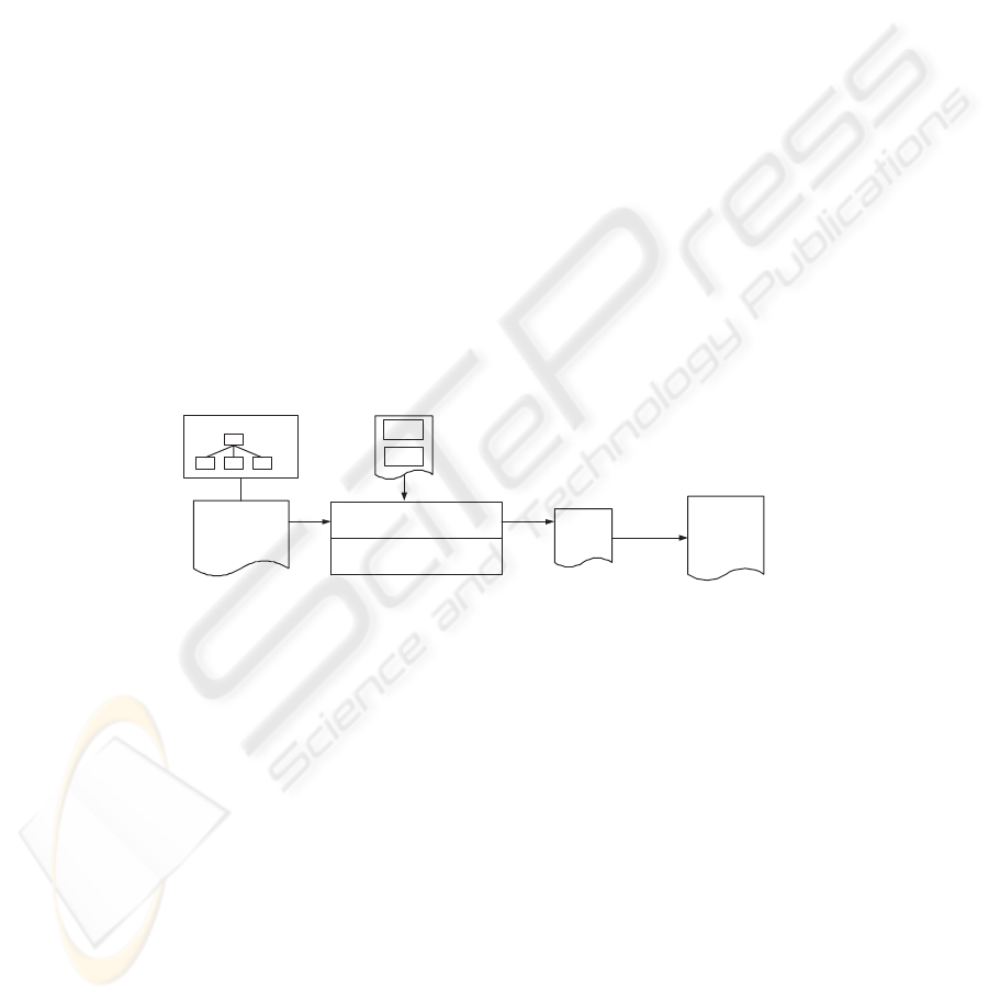
Figure 2 shows the basic structure of our model transformation framework. A trans-
formation engine takes the HRM defined source model as input, and use a template
comprise of a set of transformation rules to produce output model in a format specified
by the templates. In other words, the output from the transformation engine is a trans-
formation of the input model. We regard a model as a set of model elements that are
in correspondence with a metamodel element via the instantiation relationship. Meta-
model based transformations use only the elements of the metamodels, thus the trans-
formation description is expressed in terms of the two metamodels. The rule set in the
Figure 2 is the transformation template which is an extensible component. Different set
of templates can be used in different transformation tasks for various target platforms.
It’s in this sense that we also call the template “cartridge” to reflect the exchangeability
of templates. It’s the core component of the transformation framework. We will discuss
the characteristics of our approach in the following subsections.
HRM MetaModel
Transformation Engine
Rule Set
<<stereotype>>
ZOOM Model
(Source Model)
Result
Model/Code
rule
rule
Target
Model
Post
process
Model Level Transformation
Expression Level Transformation
Fig.2. Model Transformation Process Overview.
3.1 Source Model Representation
We use ZOOM notation to represent Platform Independent Model(PIM). ZOOM no-
tation has a textual syntax defined by BNF, which gives us a simplified way to define
and use ZOOM metamodel. Since ZOOM provides the textual syntax in a form that
most programming languages have, we are able to build an internal representation of
ZOOM models in a structure similar to Abstract Syntax Tree(AST), only the node in
the tree will be constructs of the modeling language instead of constructs of program-
ming language. However, to capture more complicated modeling language constructs
like association. We adopt mathematical collection to depict the relationships of dif-
ferent constructs. Considering it’s tree structure and such relationships, we name our
metamodel Hierarchical Relational Metamodel(HRM).
63

The use of HRM provides a way for transformation to understand and make use of
the abstract syntax and semantics of both the source and target models. Base on HRM,
we design our template based model transformation to get the information necessary to
generate target model or code from HRM-compliant models inside a model repository.
A set of interchangeable templates can be provided for model transformation between
different target technical platforms.
3.2 A Metamodeling Language
Metamodeling is a critical part of our transformation approach. It provide a mechanism
to unambiguously define modeling languages - ZOOM in our case. It is the prerequisite
for a model transformation tool to access and make use of the models. We will now
look into the design of our Hierarchical Relational Metamodel(HRM).
Hierachical Relational Metamodel. The fact that ZOOM notation has a textual syntax
defined by BNF gives us a simplified way to define and use ZOOM model’s metamodel.
From implementation point of view, metamodel defines the internal representation of
models. In programming language, this internal representation often takes the form of
Abstract Syntax Tree(AST) that can be processed by interpreter or compiler [24, 25].
Since ZOOM provides the textual syntax in a form that most programming languages
have, we are able to build an internal representation of ZOOM models in a structure
similar to Abstract Syntax Tree. The only difference is the nodes in the tree are con-
structs of the modeling language instead of constructs of programming language. To
capture more complicated modeling language constructs like association, we also adapt
mathematics collection to depict the relationships of different constructs. It is consider-
ing its tree structure and such relationships that we name this metamodel Hierarchical
Relational Metamodel(HRM).
HRM Definition. We provide the following definition of HRM:
Definition 5.1. Hierarchical Relational Metamodel is a 3-tuple: HRM = (N, C, R)
N is a set of nodes: N = {n
1
, n
2
, ... n
j
}
C is a relation on N × N, which forms a tree structure that has one root and no un-
connected nodes. Each node may have zero or more children. In other words, a node is
either a leaf(i.e. with no children) or can be decomposed as one or more children and
each child forms a subtree
R = {r
1
, r
1
... r
k
} is a set of relations between nodes, where r
i
is a relation on N × N.
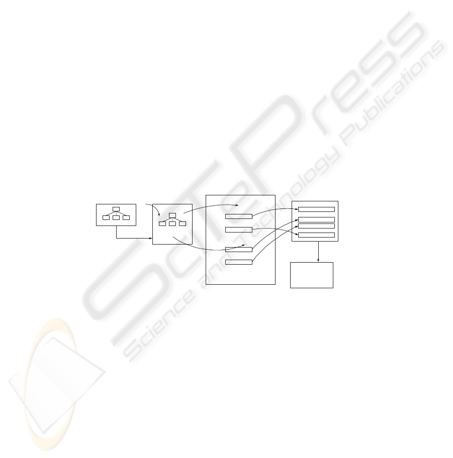
Figure 3 shows a simple class diagram that has four classes: Student, Graduate, Under-
graduate and Course. The corresponding HRM diagram is also show in Figure 3 in the
middle. This metamodel can be represented as (N, C, R) according to Definition 5.1.
More specifically, we can elaborate the contents of its three components as:
HRM component content
N { ClassDiagrm, Student, Graudate, enroll, x, y, Student.name, Graduate.advisor, ...}
C { (Student, Student.name),(Graduate, Graduate.advisor), (Graudate, Graduate.thesis), ...}
R { superClass, subClass, leftAssociationEnd, rightAssociationEnd }
superClass {(x, Student), (y, Student)}
subClass {(x, Graduate), (y, Undergraduate)}
leftAssociationEnd {(enroll, Student)}
rightAssociationEnd {(enroll, Course)}
64

Student
Attribute name
ClassDiagram
Course
Graduate
Undergraduate
Attribute id
Attribute name
Attribute advisor
Attribute thesis
Attribute minor
Student
name: String
Course
id: int
name: String
enroll
Graduate
advisor: String
thesis: String
Undergraduate
minor: String
x
y
Relation Node
x Student
y Student
superClass
Relation Node
x Graduate
y Undergraduate
subClass
LeftAssociationEnd
RightAssociationEnd
Relation Node
enroll Student
Relation Node
enroll Course
Fig.3. HRM Example of a Class Diagram.
The components superClass, subClass, leftAssociaitonEnd and
rightAssociationEnd are relations between classes Student, Graudate, Undergrad-
uate, Course and relationship enroll, x, y.
3.3 Transformation Template
The rule set shown in Figure 2 is a collection of transformation rules. Here we provide
the definition of transformation rule as followings:
Definition 3.1: A transformation rule r = P → (T
pre
, T
post
) where P defines the pattern
to select the element of source model and the template pair (T
pre
, T
post
) defines the
mapping to target model. Respectively T
pre
defines the mapping to target model before
traversing children of selected element, and T
post
defines the mapping to target model
after traversing children of selected element. The rationale of this design is closely
related to the transformation algorithm that we will talk about in the next sub section.
In our framework, the development of transformation is in a large part the pro-
cess of constructing transformation rules. The rule set in the Figure 2 is an extensible
component. Different set of templates can be used in different transformation tasks for
various target platforms. That’s why we also call the template “cartridge” to reflect the
exchangeability of templates. Template is the core component of the transformation
framework. We will show how template or rules are developed in Section 7.
3.4 Transformation Algorithm
Metamodel based transformation uses the elements of metamodel. Our adopting of Hi-
erarchical Relational Metamodel(HRM) allows us to build an internal representation of
ZOOM models in a structure similar to Abstract Syntax Tree(AST). Once metamodel
is generated as an AST like structure, it is accessible by the transformation process
through traversing the tree.
1 transformNode(node, ruleSet, outputM odel)
2 rule < −findMatchingrule(node, ruleSet) //finding the matching rule for this node
3 targetT ext < −instantiate(rule.pre, node)
4 outputModel.append(targetT ext) //getting the output text by applying pre part of the rule
5 foreach c is a child of node
6 transformNode(c, ruleSet, outputModel)
7 endforeach //traverse all the children nodes and do transf ormation on each of them
65
8 targeT ext < −instantiate(rule.post, node)
9 outputModel.append(targetT ext) //getting the output text by applying post part of the rule
We use an algorithm of “pre-order” to traverse of the tree which means each node
is visited before its children are visited and the root is visited first. The algorithm is
exemplified by the pseudo code shown in the above pseudo-code.
As we can see in Definition 3.1, a transformation rule has two mapping part, T
pre
and T
post
. They are represented as rule.pre and rule.post in the pseudo code. Shown
in the above pseudo code: rule.pre is the mapping before traversing children of se-
lected element, while rule.post is the mapping after traversing children of selected el-
ement. And as shown in line 5-7 in the pseudo code, each node in the metamode will
be visited once and all its children node will get visited. To trigger the transforma-
tion algorithm, the root node of source metamodel need to be passed, in the form of
transformNode(root, ruleSet, outputModel).
4 Model Transformation Process
To start the MDE process we need to build a platform-independentmodel that comprises
the essence of target software system. This is the only model that the developer will
create completely “by hand.” The other models are mostly generated.
The complete transformation process is depicted in Figure 4. It is divided into 5
individual steps. Now let’s walk through the transformation process step by step.
Model M metamodel
<RuleSet … target=”Java” …>
…
<Rule match=”Struct”>
<pre>
</pre>
<post>
</post>
</Rule>
<Rule match=”Struct/Field”>
<pre>
</pre>
<post>
</post>
</Rule>
...
</RuleSet>
...
...
…
...
Literate Target Code
Import java.util.*;
class A {
protected Type attr1;
…
}
step5: post processing
Block 1
Block 4
Block 3
Block 2
Instantiated Block 1
Instantiated Block 3
Instantiated Block 4
Instantiated Block 2step1: parsing
step2: traversing
step3: matching
step4: generating
Final Target Source
(see Figure 5)
(see Figure 6)
Fig.4. Model Transformation in details.
Parsing the Source Model. A source model is provided, in our case, student.zoom
in Listing 1.1. Parsing involves reading actual source code of the model, or the textual
representation of model roster and splitting it into understandable language symbols.
This is made possible by ZOOM’s formally defined syntax. A parser will parse the
textual representation of model roster and generates an internal abstract syntax tree
(AST) representation of roster, which is an object tree.
Traversing the Object Tree. Once metamodel is generated as AST, which is accessi-
ble by the transformation process through traversing the tree. We use an algorithm of
“pre-order” traversal of the tree which is introduced in section 4.3. It means each node
66

is visited before its children are visited and the root is visited first. The traversing is
exemplified by pseudo code shown in section 3.4. Since the matching metamodel node
with rule(step 3) and generating target text(step 4) happen during the process of travers-
ing. The pseudo code in section 3.4 actually shows all of these 3 steps. To trigger this
transformation algorithm, the root node of source metamodel need to be passed. In our
case, it is passing as transformNode(m1, ruleSet, outputModel), since m1 is
the root node.
As we can see in Definition 4.2, a transformation rule has two mapping part, T
pre
and T
post
. They are represented as rule.pre and rule.post in pseudo code in Section
3.4. Shown in the pseudo code: rule.pre is the mapping before traversing children of
selected element, while rule.post is the mapping after traversing children of selected
element. And as shown in line 5-7 in the pseudo code, each node in the metamode will
be visit once and all its children node will get visited.
Matching Node in Object Tree with Rule. The key step in this transformation process
is applying rules to source medels represented by their metamodels. At this point, trans-
formation engine enters into the picture. As implied in transformation rule definition, r
= (P → (T
pre
, T
post
)), to apply a rule on a certain model include both matching the pat-
tern P and implement mapping T
pre
and T
post
. The pattern P is specified to make sure
that right node is being located and used. In the pseudo code in section 3.4, rule.pre(line
3) and rule.post(line 8) function as a template for the transformation. When implement
a template, we allow both static and dynamic specification. Static specification is a ver-
batim mapping and dynamic specification can be in one of these two forms: macros or
JSP alike syntax.
Generating Target Text. The generation of target text can be as simple as output the
text included in the rule pre or emphpost elements as shown in pseudo code in section
3.4 line 3 and line 8. However, more complicated scenario can be involved in this step.
For example, in most of the cases, expressions are in different forms in source and target
model. We provide an extensible mechanism to assist the transformation, or mapping.
The result of these steps is Literate Target Code. It will be used as input in the final step,
post processing.
Post Processing. The Literate Target Code generated in Step 4 as shown in Figure 4
may or may not in a desirable order that fits to the target technical platform. Post pro-
cessing is responsible to rearrange the Literate Target Code in a desirable style that fits
to the target technical platform. Here we treated the Literate Target Code as pieces of
segment that can be flexibly rearranged. A post process goes through all these pieces
and place each of them in right places in final models or code. This frees the model
transformation engine from the details of contextual requirements of target platform.
This approach has a similar style as proposed in Knuth’s Literate Programming [26].
Literate programming is a methodology that combines a programming language with
a documentation language, hereby making programs more robust, more portable, more
easily maintained, and arguably more fun to write than programs that are written only
in a high-level language.
After all the above transformation steps, the results are models or source code of
target platform. In our example, the results are a group of Java source code.
67

5 Related Work
A number of partial solutions to describe and implement model transformation are cur-
rently available. Some of these are applicable only in a limited domain, or provide very
low-level abstractions for transformations [27].
5.1 AndroMDA
AndroMDA [28] is a code generation tool that takes a UML model as input and gen-
erates source code as output. It adopts a template-based transformation methodology
similar to ours in a degree but differs significantly in handling of metamodel. Using a
series of template files (which you can customize if you wish), AndroMDAcan produce
source code from a UML model in any programming language. Default templates exist
to generate Java code (and in particular J2EE code). AndroMDA was designed to get
the information necessary to generate code from MOF compliant models inside a MOF
repository.
Both AndroMDA and our approach are template-based, metamodel-based model
transformation frameworks that support code generation. Both have an extensible ar-
chitecture consists of cartridges. These cartridges generate the code specific to a certain
concrete technical platform. However, the fundamental difference between these two
approaches are the metamodel that they base upon. AndroMDAuses MOF while we use
HRM. Because of the complexity of the MOF compliant metamodel, when AndroMDA
traverses its AST objects, it has to access them via a proprietary JMI interfaces, meta-
model facades. Comparing to AndroMDA, our approach simplified the transformation
template development by adopting a concise, tree-structure metamodel.
5.2 XSLT Style
Extensible Stylesheet Language Transformations (XSLT) [29] is an XML-based lan-
guage used for the transformation of XML documents into other XML. The XSLT
processor ordinarily takes two input files - an XML source document, and an XSLT
stylesheet and produces an output document. The XSLT stylesheet contains the XSLT
program text and is itself an XML document that describes a collection of template
rules: instructions and other hints that guide the processor toward the production of the
output document. Since XSLT must be written in terms of the concepts in the source
XMI document (model), and object (or element) creation explicit, the style is highly
procedural and due to its XML basis, the concrete syntax is very user unfriendly. As
such, it is unsuitable for one of the major goals of a declarative transformation language
- which is to communicate mapping specifications to human beings.
Comparing to XSLT, our approach provides a much more user friendly template
language syntax. In most cases, transformation developer just need to fill in the syntax
details of target platform when writing the specific template.
5.3 QVT(Queries/Views/Transformations)
In the Model-Driven Architecture(MDA), QVT (Queries/Views/Transformations) is a
standard for model transformation defined by the Object Management Group. Presently
68

there are several products (commercial or open source) that claim compliance to the
QVT standard. QVT defines a standard way to transform source models into target
models. Duddy et al propose a transformation language which will meet the require-
ments of QVT RFP, and several others besides [30]. The language is declarative and
patterns based. Transformation descriptions are explicitly reusable and modular. Rules
that make up such descriptions may be aspect-driven, allowing for transformations to
be written to address semantic concepts rather than structural features.
Since the abstract syntax of QVT conform to MOF 2.0 metamodel, one of the
strength in our approach again is adopting a concise, tree-structure metamodel, HRM.
Because of the simplified metamodel, when transformation engine traverses its AST
objects, it can have direct access to the properties of the objects. This facilitates model
transformer to develop transformation template in a easier and quicker way.
6 Conclusions
In this paper we present a template based model transformation framework using Hi-
erarchical Relational Meta-model (HRM). By adopting Z-based Object-Oriented Mod-
eling notation (ZOOM) as the formal modeling notation, this model transformation
framework provides benefits consist of: 1) readability and rigorousness of meta-model
definitions; 2) simplicity of transformation definition; and 3) extensibility of transfor-
mation templates.
The current development of this project has made substantial progress and further
research effort will be mainly focusing on two things: one is to extend the capacity of
current framework; the other is to further prove the validity of this research by building
more sophisticate cases. With these two major parts in place, we can further compare
our approach with other model transformation mechanisms to verify the advantages
of our framework, which is providing a simple, effective, and practical way to define
model transformations.
References
1. Kent, S.: Model driven engineering. In: Proc. IFM 2002, Springer-Verlag (2002) LNCS
Vol. 2335.
2. Balasubramanian, K., Gokhale, A., Karsai, G., Sztipanovits, J., Neema, S.: Developing ap-
plications using model-driven design environments. Computer 39 (2006) 33
3. Gray, J., Lin, Y., Zhang, J.: Automating change evolution in model-driven engineering.
Computer 39 (2006) 51
4. Poole, J.: Model-driven architecture: Vision, standards, and emerging technologies. In:
ECOOP’01 – Object-Oriented Programming. (2001)
5. Rouvoy, R., Merle, P.: Towards a model-driven approach to build component-based adapt-
able middleware. In: ARM ’04: Proceedings of the 3rd workshop on Adaptive and reflective
middleware, New York, NY, USA, ACM Press (2004) 195–200
6. (UML
T M
2.0 Superstructure Specification) OMG Document ptc/03-08-02 (August, 2003).
7. France, R.B., Ghosh, S., Dinh-Trong, T., Solberg, A.: Model-driven development using uml
2.0: Promises and pitfalls. Computer 39 (2006) 59
69

8. Rumbaugh, J., Jacobson, I., Booch, G.: The Unified Modeling Language reference man-
ual.(1998)
9. Sendall, S., Kozaczynski, W.: Model transformation: The heart and soul of model-driven
software development. IEEE Software 20 (2003) 42–45
10. D’Ambrogio, A.: A model transformation framework for the automated building of per-
formance models from uml models. In: WOSP ’05: Proceedings of the 5th international
workshop on Software and performance, New York, NY, USA, ACM Press (2005) 75–86
11. Bzivin, J., Farcet, N., Jzquel, J.M., Langlois, B., Pollet, D.: Reflective model driven engi-
neering. In: ”UML” 2003 - The Unified Modeling Language, Springer-Verlag (2003) LNCS
Vol. 2863.
12. Mukerji, J., Miller, J.: (Model-Driven Architecture) http:// www.omg.org/cgi-
bin/doc?ormsc/2001-07-01.
13. Group, O.M.: (Meta-Object Facility 1.4) OMG Document formal/2002-04-03.
14. (MOF 2.0 Query / Views / Transformations RFP) OMG Document ad/04-10-02.
15. (MOF QVT final adopted specification) OMG Document ad/05-11-01.
16. Spivey, J.M.: The Z Notation: A Reference Manual, 2nd Ed. (1992)
17. Woodcock, J., Davies, J.: Using Z Specification, Refinement, and Proof. Prentice Hall
Europe (1996)
18. Wordsworth, J.B.: Software Development with Z. Addison Wesley, Boston, MA (1992)
19. Jia, X.: An approach to animating Z specifications. In: Proc. 19th Annual IEEE Int’l Com-
puter Software and Applications Conf. (COMPSAC 1995), Dallas, Texas, USA (1995) 108-
113
20. Jia, X.: (The ZOOM Notation - A Reference Manual) Technical Report, DePaul University,
2004.
21. Jia, X., Steele, A.: Incorporating uidls into model-driven development. In: Proceedings of
UIXML2004, Gallipoli, Italy (2004)
22. Qin, L., Liu, H., Jones, C., Jia, X.: An Integrated Event-Driven Framework Supporting MDD.
In: Proc. of the 2004 Midwest Software Engineering Conference (MSEC’04), Chicago,IL
USA. (2004) 32–44
23. Lopes, C., Hrsh, W.: (Separation of concerns) Technical Report, Computer Science School,
Northeastern University, Boston, US, 1995.
24. Aho, A.V., Ullman, J.D.: Theory of Parsing, Translation and Compiling. Prentice Hall
Professional Technical Reference (1973)
25. Wile, D.S.: Abstract syntax from concrete syntax. In: ICSE ’97: Proceedings of the 19th
international conference on Software engineering, New York, NY, USA, ACM Press (1997)
472–480
26. Knuth, D.E.: Literate programming. CSLI Lecture Notes (2003)
27. Czarnecki K., S.H.: Classification of model transformation approaches. In: OOPSLA. (2003)
28. (Andromda website) http://www.andromda.org/.
29. (W3C), T. W. W. W. C.:(XSL Transformations (XSLT) Version 1.0)
http:// www.w3c.org/TR/xslt.
30. et al, K.D.: Model transformation: A declarative, reusable patterns approach. (In: Proceed-
ings of the Seventh IEEE International Enterprise Distributed Object Computing Conference
(EDOC03))
70
