
Modeling with Service Dependency Diagrams
Lawrence Cabac, Ragna Dirkner and Daniel Moldt
University of Hamburg, Department of Informatics
Vogt-Kölln-Str. 30, D-22527 Hamburg, Germany
Abstract. This paper describes the usage of component diagram like models
for the analysis and design of dependencies in multi-agent systems. As in other
software paradigms also in multi-agent-based applications there exist dependen-
cies between offered and required services, respectively the agents that offer or
require those services. In simple settings it seems superfluous to model or ana-
lyze those dependencies explicitly because they are obvious. In complex settings,
however, these dependencies can grow rather confusingly big and can cause mis-
understandings among the developers of the system. Here it is useful to achieve a
visualization of those dependencies by analyzing the given multi-agent applica-
tion and displaying these in a diagram. The diagram gives a clear illustration of
the overall structure of the system and therefore forms a basis for the discussion
of the architecture. In addition, the diagram may be used for the documentation
of the system. A dependency diagram technique together with a tool integration
is presented in this paper.
1 Introduction
One key factor for the successful operation of multi-agent systems is the smooth com-
munication between the agents. Usually, interactions are modeled in detail using inter-
action diagrams and agent protocols [1,9,12]. Static aspects of the system are often not
modeled explicitly, although they are important for the understanding of the structural
architecture of the multi-agent system. One example of such static aspects is the depen-
dency relation that exists between agents. In order to attain a goal, most agents have
to communicate with other agents. Thus there exists a dependencies between agents in
almost every multi-agent system, which are related to the interaction structure of the
system.
During the development of several multi-agent applications in our teaching projects
we recognized that the absence of a model illustrating the overall structure of the system
turns out to be a big problem. For example often there are diverse opinions among the
developers which agent has to initiate a particular interaction. This is our motivation to
model the dependencies with a UML component diagram, which are modified to some
extend by adjusting the syntax to fulfill our needs. Surely this calls for tool integration
and for that reason we have developed a plugin for RENEW [11].
In MULAN [13], offered and required services are explicitly defined in the agent’s
configuration file (the agents initial knowledge base). Our plugin manages to use this
source to generate a dependency diagram. Another benefit of the tool is that it offers
synchronization between the dependency diagram and the agent’s configuration file.
Cabac L., Dirkner R. and Moldt D. (2008).
Modeling with Service Dependency Diagrams.
In Proceedings of the 6th International Workshop on Modelling, Simulation, Verification and Validation of Enterprise Information Systems, pages
109-118
DOI: 10.5220/0001742401090118
Copyright
c
SciTePress

We start this paper by pointing out that during the design of agent services the right
level of abstraction and its variation is of great importance to the results in system de-
sign. More than one type of dependency may exist among agents and services. Thus,
we distinguish between soft and hard dependencies in Section 2. We propose the depen-
dency diagram for the modeling of hard service dependencies, which is a variation of
the UML component diagram. Section 3 presents the dependency diagram that shows
clearly the dependency hierarchy of agents. Finally, we present the tool for the genera-
tion of the dependency diagram from MULAN knowledge base files. With this RENEW
plugin it is also possible to create new dependency diagrams or edit existing diagrams
(Section 4).
2 Service Dependencies
In the context of multi-agent systems we understand services as collections of agent
actions that serve a common purpose. A service is realized by one or more agent proto-
cols. In general a service may be requested by other agents. This implies an interaction
of (at least) one agent with (at least) one other agent. As a consequence, to be able to
access a service, its interface has to be published.
During the design phase of the system the developers have to decide on the level of
abstraction of the services and their published interface.
Let us consider for example an agent that plays board-games. We can describe the
services of the agent on a very abstract level and say the service is playing board-games.
On a very low level of abstraction we can describe the services of the agent through the
actions he performs, so we say the agent offers services like throw dice, move peg, and
so on.
The challenge for the developers is to find the right level of abstraction, that is
abstract enough to get an idea of the offered services as a whole and detailed enough
to recognize if two agents perform similar tasks. Through their flexibility in regard to
the choice of the level of abstraction the services are suitable for modeling the overall
structure of big as well as small systems without getting too complex or too trivial
representations in the modeled diagrams. Most agents use services of other agents to
accomplish their goals or even to provide their own services (by delegation). Thus, if an
agent requires a service from another agent, we recognize a dependency between agent
and offered service.
We distinguish between hard/static dependencies and soft/dynamic dependencies.
Hard dependencies are explicitly specified by the developer. In MULAN/CAPA applica-
tions they are defined in the initial knowledge base file. The hard dependencies describe
a minimum set of services that are required by an agent to do something useful. Another
type of dependencies between agents are soft dependencies, which give a description
of the communication structure between agents. If an agent requires an answer from
another agent within a conversation, there exists a soft dependency between those two
agents. The schemas of the conversations are typically defined as interaction proto-
cols [9]. We apprehend protocols as implementations of a complex agent actions that
are assigned to one or more services. Thus soft dependencies can also be regarded as de-
110
Requester
Participant
<<agent>>
Participant
<<agent>>
Requester
<<service>>
participate
<<requiredBy>>
request
agree
failure
inform-done
refuse
inform-result
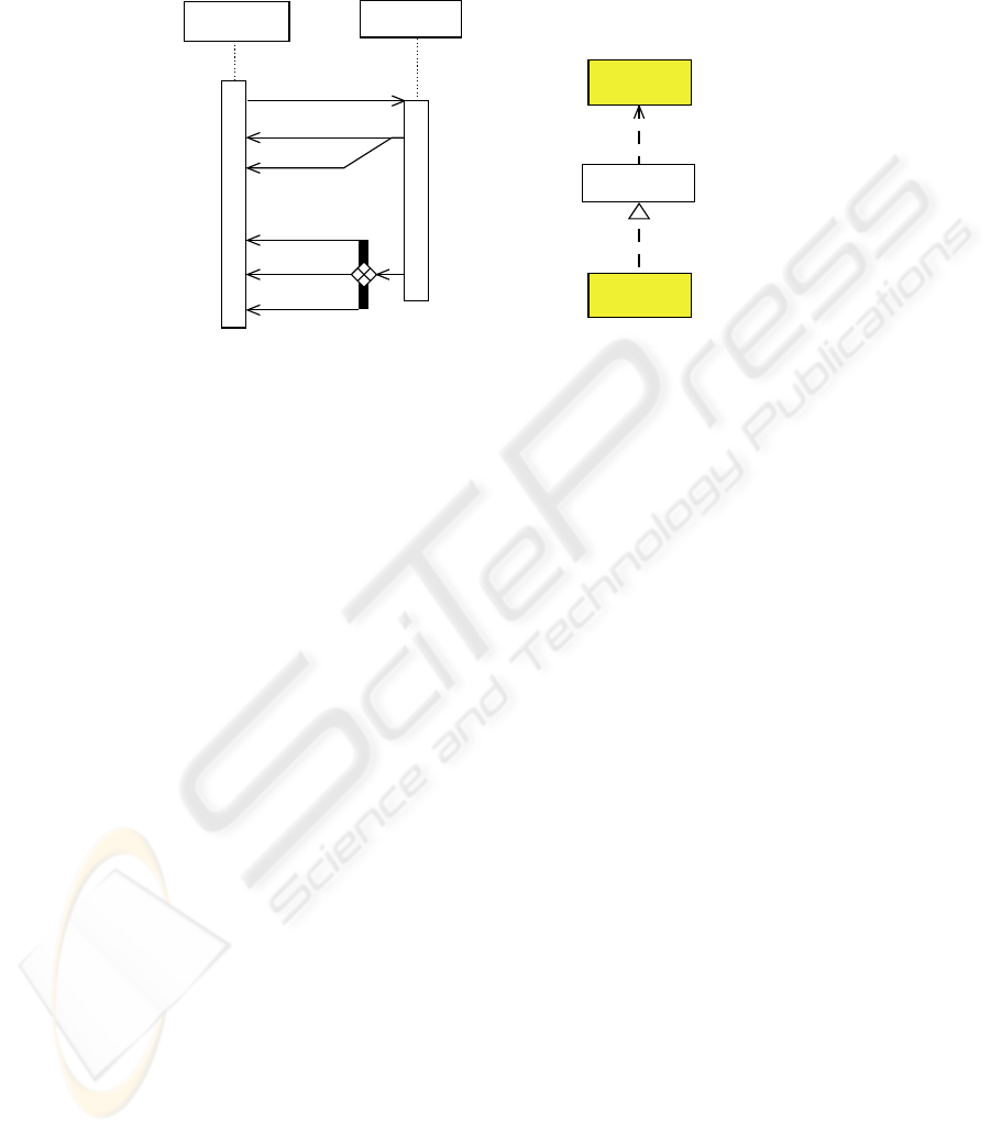
FIPA Request Protocol
Dependency between
the two agents in the
FIPA Request Protocol
<<offers>>
Fig.1. FIPA Request protocol and a representation of dependencies.
pendencies between agents and services. In this paper we propose a modeling technique
for hard dependencies. We do not deal with soft dependencies.
We recognize a dependency between an agent and a service that is offered by an-
other agent, if the first agent starts an interaction with the second agent. To illustrate
this we use the well known FIPA Request protocol [10] presented in Figure 1. The Par-
ticipant in the Request protocol offers a service to perform a certain task – lets say the
service participate. The Requester wishes a task participate to be performed by the Par-
ticipant. This implies that the Requester sends a message to the Participant and waits
for an answer. The service offered by the Participant is completed with an answer to
the initial request. Thus a hard dependency exists, which is modeled in the right part of
the figure as a fragment of a dependency diagram. Services can be required by several
agent and they can also be offered by multiple agents. Thus, the dependency does not
exist directly between the two agents, instead – as pointed out above – the dependency
exist between an agent and an offered service.
In general, we seek for a hierarchical structure in a dependencydiagram. This allows
for code reuse in the system, composability and easy reconfiguration. Interdependen-
cies (cyclic dependencies) between agents are undesired, first because they can cause
deadlocks in the systems configuration and second because they complicate the substi-
tution of agents. We believe that the explicit modelling find such problematic aspects in
a system design and help the developer to eliminate them.
3 Modeling Service Dependencies
We model hard dependencies with adapted UML component diagrams. Usually, com-
ponent diagrams are used to model the constitution of replaceable software constructs
and their relationships. Other parts of the component diagram are classes, objects and
111

interfaces [15, p. 139-171]. In the following section we describe how the elements of
the agent’s context (i.e. agents, services and the dependency relations) can be modeled
with elements of the component diagram. In doing so we also highlight the differences
between the elements and suggest special notations where it seems useful.
A service is an abstraction of a set of (complex) agent actions that serve a common
purpose. Several services may be provided by one agent and several agents may offer
the same services. This definition is very similar to the definition of interface in the
UML superstructure [15, p. 82]: "An interface is a kind of classifier that represents a
declaration of a set of coherent public features and obligations. An interface specifies a
contract; any instance of a classifier that realizes the interface must fulfill that contract."
So we model services as an interface but add the stereotype “service”. We make this
distinction for two reasons. First an agent has in contrast to an object the ability to
break contracts, so services are indeed also an obligation to fulfill a specified tasks but
there is no definitive certainty that this will be done. Another reason is that we would
like to use the agent and service figures together with the regular class and interface
notation and the introduction of a new stereotype gives us the ability to do so without
getting confused about the terms.
Agents are modeled as special components.For the same reasons as described above
we use the stereotype «agent» for the agent components. Note that the agent figures
in the diagram describe the static configuration of the agents, not the agent instances at
runtime.
The relation between interfaces and components is modeled in a UML component
diagram by an arc. Offered interfaces are connected to the component via a dashed arc
with a closed triangle top, which points to the interface. This notation is also practical
for representing the relation between agents and their offered services. To model re-
quired interfaces the component diagram uses a dashed arc with the stereotype «use»
and an open triangle top that also points to the interface. In section 2 we pointed out the
benefits of hierarchical dependencies. To get a dependency diagram with a hierarchical
layout we use an arc that points in the opposite direction to connect agents with their
required services. As for the service elements we introduce the stereotypes «offers»
and «requiredBy» to emphasize the affiliation of the relation elements to the agent
context.
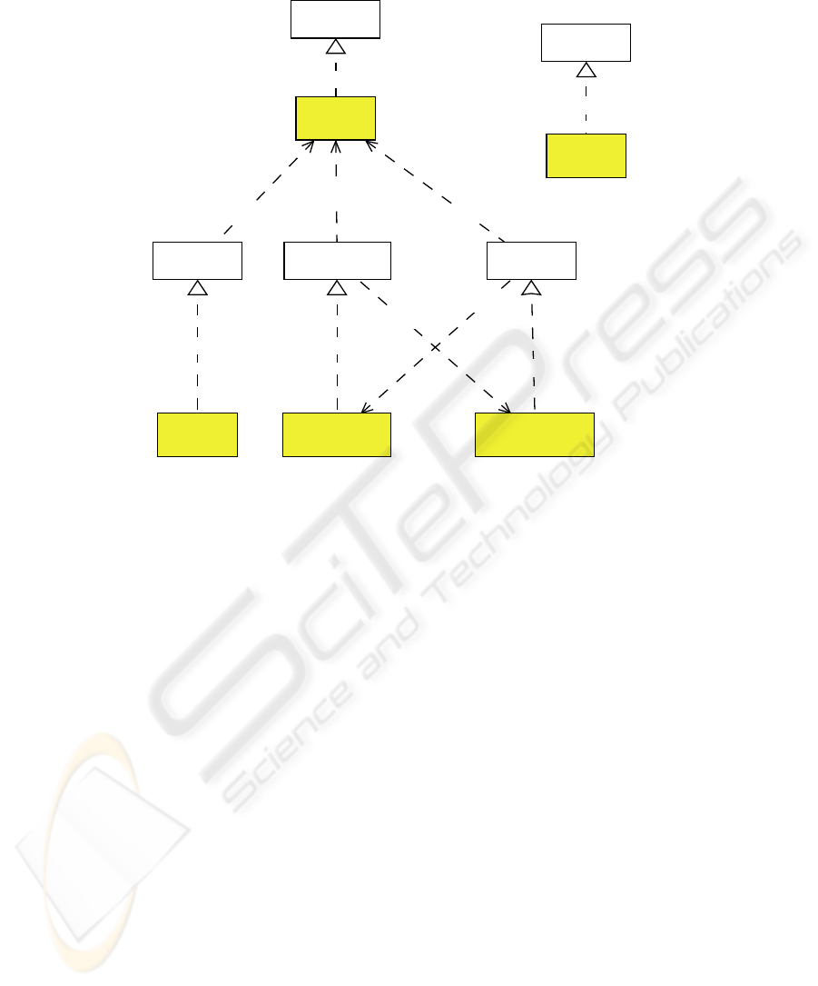
Figure 2 shows a dependency diagram as described above. To better distinguish
between agents and services the agent figures are highlighted by a colored background.
The figure shows a snapshot of a workflow management system in development,
giving an overview of the agents in the system. In addition, a developer can easily iden-
tify potentially problematic areas. In this example we find two problems: First, between
the agents Administration and ClientInteractionexists a two-way depen-
dency. A two-way dependency may indicate that the agents could be implemented as
one agent or, as in this case, the developers of one agent have a misconception of the
tasks of the agent. Second, the agent Wfenact is not connected to the other agents. An
isolated agent means that this agent does not interact with other agents of the system.
Here, this situation is not intended. Both situations are therefore undesired and should
be changed in the further development process. The developer may be supported in
112
<<offers>>
<<requiredBy>>
<<agent>>
User
<<service>>
wfenact
<<service>>
wfms
<<requiredBy>>
<<requiredBy>>
<<service>>
user
<<offers>>
<<agent>>
Wfms
<<requiredBy>>
<<offers>>
<<offers>>
<<service>>
administration
<<service>>
interaction
<<agent>>
Administration
<<agent>>
ClientInteraction
<<requiredBy>>
<<offers>>
<<agent>>
Wfenact
Fig.2. Dependencies of the distributed workflow management system in development.
finding such structural anomalies automatically by the modeling tool that is described
in the next section.
4 Tool Description
The dependency diagram tool is a plugin for RENEW [11]. The plugin has two main
functionalities. First, it generates the dependency diagram from existing MULAN
knowledge base files. Second, it offers tools for creating and editing dependency di-
agrams.
Figure 3 shows a screen shot of the development of the workflow management sys-
tem with the dependency diagram tool. In the upper left corner is the RENEW menu
bar with the standard palettes and the dependency diagram palette. Beneath, the depen-
dency diagram is shown. In the diagram the agent figure User is selected. The right
hand side of the figure shows the knowledge base editor (KBE) with the knowledge
base of the agent User.
For generating a diagram the tool searches (recursively) for knowledge base files
in a user-defined directory. For each knowledge base found an agent figure is created.
A knowledge base contains a list of offered services and a list of the agent’s required
services. For each service in the lists the corresponding service figure and the agent
figure are connected. A new service figure is created, if the service is not already present
113
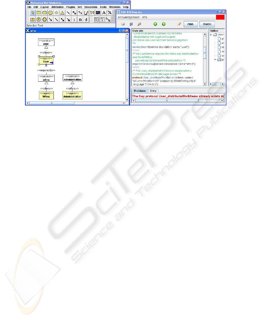
Fig.3. Screen shot of the development with the dependency diagram tool.
in the drawing. For the user’s convenience the tool provides a simple automatic layout
mechanism.
In addition to the possibility to use all standard drawing tools of RENEW the plugin
offers some new editing functions. These are offered as three tools for editing depen-
dency diagrams: an agent figure tool, a service figure tool and a dependency connection
tool (see the last three items in the lower RENEW tool bar in Figure 3). The dependency
connection tool is used for drawing the arcs between agent and service figures. The ar-
row type and the inscription depend on the direction of the arc – see Section 3. Arrows
are adapted automatically while they are drawn so that the two arc types can be drawn
with the same tool.
A special function of the dependency diagram is the KBE handle, which is part of
the agent figure. With a click on the handle (a blue arc in the bottom right corner of
the figure that is visible when the figure is selected), the knowledge base of the agent
is opened in the KBE for further inspection or editing. This is especially useful for
debugging purposes.
By first generating a dependency diagram and then editing it, one faces an inconsis-
tency between the diagram and the code it is generated from. To minimize such conflicts
between diagrams and knowledge bases a round-trip engineering system was realized.
It preserves the consistency of knowledge bases and dependency diagram by automati-
cally transferring every change in the dependency diagram to the knowledge bases. For
example, when the service administration is connected to the agent User via a
dependency arc, a new service-description is inserted in the list of the required services
in the knowledge base. This also works in the other direction. However, changes in the
knowledge base are not transferred immediately to the dependencydiagram, but as soon
as the knowledge base is saved.
A detailed description of the dependency diagram tool and the round-trip engineer-
ing system can be found in [6].
114
<<plugin>>
Renew Ant
<<service>>
de.renew.ant
<<plugin>>
Renew Formalism Gui
<<plugin>>
Renew Util
<<service>>
de.renew.util
<<plugin>>
Renew Simulator
<<plugin>>
Renew Gui Prompt
<<service>>
de.renew.simulator
<<plugin>>
Renew Misc
<<plugin>>
Renew NetComponents
<<service>>
de.renew.nc
<<plugin>>
Renew MulanComponents
<<service>>
de.renew.mulancomponents
<<service>>
de.renew.gui
<<plugin>>
Renew Gui
<<service>>
de.renew.misc
<<service>>
ch.ifa.draw
<<plugin>>
Renew JHotDraw
<<service>>
de.renew.formalism.gui
<<service>>
de.renew.prompt
<<plugin>>
Renew Prompt
<<plugin>>
Renew Formalism
<<service>>
de.renew.formalism
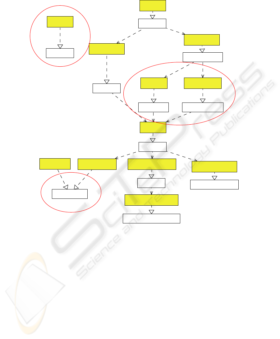
Fig.4. Cutout of the renew plugin structure.
Usage in Other Domains
The dependency diagram tool is not bound to agent dependencies but can also be used
for modeling other component based, hierarchical structured systems. Another exam-
ple of such a hierarchical system in our context is the plugin structure of RENEW. As
the agents in the MULAN-system every plugin contains a configuration file where the
required plugins are declared. Therefore the dependency diagram tool can be used for
generating a dependency diagram of the plugin structure without much additional ef-
fort. Unlike in the agent system also the dependencies of the required plugins have to be
declared recursively. A function to remove this transitive arcs in the diagram is there-
fore very useful. The example in Figure 4 shows a cutout of the RENEW plugin structure
without transitive arcs.
115

Similar to the agents’ knowledge bases in the MULAN-system every plugin in RE-
NEW contains a configuration file, in which required services are declared. Therefore,
the dependency diagram tool manages to generate dependency diagrams of the plugin
dependency structure. However, in contrast to the multi-agent system also the depen-
dencies of the required plugins have to be recursively declared. A functionality to re-
move this transitive arcs in the diagram is therefore in this context very useful and in
development.The example in Figure 4 shows a fragment of the RENEW plugin structure
without the manually removed transitive arcs.
5 Related Work
Our definition of hard dependencies is comparable with the definition of service depen-
dencies in [2]. A definition of soft dependencies can be found in the PASSI method.
There a soft dependency exists if a service is not required, but “helpful or desirable”
[5, p. 6]. This notion conflicts with ours where soft dependencies subsume the hard
dependencies.
Most software developing methodologies contain a technique for modeling some
kind of dependencies between their components. In the following paragraph we
will consider two examples from the agent oriented context, TROPOS and AGR
(Agent/Group/Role) and have a look how the dependency diagram can be used in other
component based domains.
The TROPOS methodology distinguishes four kinds of dependencies between
agents, from hard dependencies (resource) to soft ones (soft-goal). [14] shows how
TROPOS dependency relations can be expressed in UML for real time systems.
A hard dependency in our definition could be a resource dependency, a goal depen-
dency or a task dependency in TROPOS, depending on the kind of service. We want
to abstract as much as possible from the agent internals to get a clear image of the
system structure, so the distinction between different kind of services in matters of the
underlying action is not useful for our needs.
Another agent oriented modeling technique, that describes dependencies between
agents is AGR, which stands for Agent/Group/Role. In [8] the authors show how the
organizational structure of an agent based system can be modeled using the AGR tech-
nique. One of the proposed diagrams, the organizationalstructure diagram, shows roles,
interactions and the relations between roles and interactions. This diagram is compara-
ble to the dependency diagram. In both diagrams an arc from an agent or respectively
the role the agent plays, means that the agent starts an interaction. Differences between
the diagrams come off additional elements in the organizational structure diagram. First
also the groups to which the roles belongs are modeled. Second, the situation that every
agent in a specific role must be member in another role is modeled as a direct relation
between the two roles. In MULAN/CAPA-Systems there are (for now) no elements like
groups or roles, so the advanced modeling possibilities of an organizational structure
diagram is not suitable in this context.
As well as in the agent context, also in other component based systems it is impor-
tant to model the dependencies between components. One example of a well known
component system is the Eclipse Framework with its numerous plugins. The visualisa-
116

tion of the dependencies between different plugins is complex and no sufficient com-
mercial tools exist that can visualize the structure of the whole system appropriately.
6 Conclusions and Outlook
We presented a technique and a tool for explicit modeling of dependencies between
agents and services. The benefit from this technique is an intuitive diagram consisting
of only four elements. The use of the proposed diagram helps a software developer
to get an overview on the overall structure of the system and to identify desired or
undesired dependencies hidden in the source code. Furthermore, the diagram may be
used for design, presentation and documentation purposes.
With the dependency diagram tool and the round-trip engineering system develop-
ers can generate and use the dependency diagram without additional effort. The depen-
dency diagram always shows an up-to-date documentation of the system.
The dependency diagram can not be used only for showing dependencies between
agents but also for other components. The current version of the tool, for example, can
generate diagrams that show the RENEW plugin dependencies. Because the RENEW
plugins and the plugin system were conceptually based on agent technology, this addi-
tional functionality was achieved with very little effort (compare with [4]).
The dependency diagram tool can be extended in many directions. It is possible to
show additional informations of the knowledge bases such as comments to the required
or offeredservices. The comments can be shown as UML note figures that are connected
to the corresponding agent figures.
Another interesting point is to analyze the connection between agent interaction
diagrams and dependency diagrams.
The work on dependency modeling presented in this paper is one building block
of a broader approach on agent-oriented software engineering based on Petri nets and
other graphical modeling formalisms. It includes research in the context of MULAN,
CAPA and also application development (see [3,7,13]).
References
1. AUML. Agent UML. Webpage, 2004. http://www.auml.org/.
2. Lars Braubach, Alexander Pokahr, Dirk Bade, Karl-Heinz Krempels, and Winfried Lamers-
dorf. Deployment of distributed multi-agent systems. In Franco Zambonelli Marie-
Pierre Gleizes, Andrea Omicini, editor, 5th International Workshop on Engineering Societies
in the Agents World, pages 261–276. Springer-Verlag, Berlin, 8 2005.
3. Lawrence Cabac, Michael Duvigneau, Michael Köhler, Kolja Lehmann, Daniel Moldt, Sven
Offermann, Jan Ortmann, Christine Reese, Heiko Rölke, and Volker Tell. PAOSE Settler
demo. In First Workshop on High-Level Petri Nets and Distributed Systems (PNDS) 2005,
Vogt-Kölln Str. 30, D-22527 Hamburg, March 2005. University of Hamburg, Department for
Computer Science.
4. Lawrence Cabac, Michael Duvigneau, Daniel Moldt, and Heiko Rölke. Applying multi-
agent concepts to dynamic plug-in architectures. In Joerg Mueller and Franco Zambonelli,
editors, Agent-Oriented Software Engineering VI: 6th International Workshop, AOSE 2005,
117

Utrecht, Netherlands, July 21, 2005. Revised Selected Papers, volume 3950 of Lecture Notes
in Computer Science, pages 190–204. Springer-Verlag, June 2006.
5. M. Cossentino and C. Potts. PASSI: a process for specifying and implementing multi-agent
systems using UML. http://www-static.cc.gatech.edu/classes/AY2002/
cs6300_fall/ICSE.pdf.
6. Ragna Dirkner. Roundtrip-Engineering im PAOSE-Ansatz. Diploma-thesis, University of
Hamburg, Department Informatics, 2006.
7. Michael Duvigneau, Daniel Moldt, and Heiko Rölke. Concurrent architecture for a multi-
agent platform. In Fausto Giunchiglia, James Odell, and Gerhard Weiß, editors, Agent-
Oriented Software Engineering III. Third International Workshop, Agent-oriented Software
Engineering (AOSE) 2002, Bologna, Italy, July 2002. Revised Papers and Invited Contri-
butions, volume 2585 of Lecture Notes in Computer Science, Berlin Heidelberg New York,
2003. Springer-Verlag.
8. Jacques Ferber, Olivier Gutknecht, and Fabien Michel. From agents to organizational view
of multi-agent systems. In Paolo Giorgini, Jörg Müller, and James Odell, editors, Agent-
Oriented Software Engineering IV, pages 214–230, 7 2003.
9. FIPA. Foundation for Intelligent Physical Agents, 2007. http://www.fipa.org.
10. Foundation for Intelligent Physical Agents. FIPA Request Protocol Specification, version
2002/12/06 edition, 2002.
11. Olaf Kummer, Frank Wienberg, and Michael Duvigneau. Renew – the Reference Net Work-
shop. Available at: http://www.renew.de/, May 2006. Release 2.1.
12. James Odell, H. Van Dyke Parunak, and Bernhard Bauer. Extending UML for agents. In Gerd
Wagner, Yves Lesperance, and Eric Yu, editors, Proc. of the Agent-Oriented Information
Systems Workshop at the 17th National conference on Artificial Intelligence, pages 3–17,
2000.
13. Heiko Rölke. Modellierung von Agenten und Multiagentensystemen – Grundlagen und An-
wendungen, volume 2 of Agent Technology – Theory and Applications. Logos Verlag, Berlin,
2004.
14. Carla T. L. L. Silva and Jaelson Castro. Modeling organizational architectural styles in
uml: The tropos case. In Oscar Pastor and Juan Sánchez Díaz, editors, Anais do WER02 -
Workshop em Engenharia de Requisitos, pages 162–176, 11 2002.
15. Unified modeling language: Superstructure. http://www.omg.org/docs/formal/
05-07-04.pdf, Juli 2005.
118
