
TOWARDS A SEMIFORMAL DEVELOPMENT METHODOLOGY
FOR EMBEDDED SYSTEMS
Lucas Cordeiro
1,2
, Raimundo Barreto
1
1
Departamento de Ciˆencia da Computac¸˜ao - Universidade Federal do Amazonas (DCC/UFAM), Brazil
2
Centro de Ciˆencias, Tecnologia e Inovac¸˜ao do P´olo Industrial de Manaus (CTPIM), Brazil
Meuse Oliveira
Centro Federal de Educac¸˜ao Tecnol´ogica de Pernambuco (DAES/CEFET-PE), Brazil
Keywords:
Agile methodologies, Embedded Agile Development, Embedded Software Verification, Platform-Based De-
sign, Real-time Software.
Abstract:
In recent days, the amount of functions has increased significantly in embedded products so that systems de-
velopment methodologies play an important role to ensure the product’s quality, cost, and time. Furthermore,
this complexity coupled with constantly evolving specifications, has led to propose a semiformal develop-
ment methodology to support the building of embedded real-time systems. A platform-based design approach
has been used to balance costs and time-to-market in relation to performance and functionality constraints.
We performed three expressive case studies and we concluded that the proposed methodology significantly
reduces design time and improves software modularity and reliability.
1 INTRODUCTION
Embedded computersystems are used in a wide range
of sophisticated systems from mobile phones to Set-
top boxes providing connectivity alternatives to PCs
(personal computers). The amount of functions de-
manded for these systems has increased so signifi-
cantly that developmenttime becomes difficult to pre-
dict and control. As the system complexity increases,
its development lifecycle is also affected. Because
of that, system development methodologies must be
applied in order to substantially reduce manufactur-
ing and design costs, to manage the product require-
ments (scope) and timeline, and to meet the system’s
constrains (e.g., energy consumption, execution time,
memory footprint).
Therefore, in practice, current design methodolo-
gies are no longer adequate and it is evident that there
is a crisis in embedded-software design (Vicentelli,
2002). Several development methodologies that are
used successfully to produce software that runs on
the PCs are not appropriate for developing embedded
systems. These devices contain very different char-
acteristics such as dedicated hardware and software,
and constraints that are not common to PCs based
systems. Furthermore, severe coding errors such as
stack/memory overflow, register address access, and
timing must be avoided when designing embedded
software (ESW). In order to get rid of such errors,
system designer needs techniques that allow them to
exhaustively traverse the reachable state space.
Proofs of properties have been around since the
early days of computer science, but academic ad-
vancements were routinely ignored by industry. Po-
tentially, one of the main difficulties to apply formal
methods in industry is that software engineers con-
sider that formal methods are difficult to understand
and use. Furthermore, some situations complicate the
application of formal methods in real projects such
as the demand for complex systems and the fact that
several changes in the user requirements might take
place. To alleviate this problem, agile methodolo-
gies have been introduced into the industry in the last
decade in order to attempt a useful compromise be-
tween no process and too much process.
Based on this context, our main aim is to propose
a semiformal development methodology in order to
balance costs and time-to-market in relation to per-
formance and functionality constraints. This method-
ology is mainly composed of well-known prac-
5
Cordeiro L., Barreto R. and Oliveira M. (2008).
TOWARDS A SEMIFORMAL DEVELOPMENT METHODOLOGY FOR EMBEDDED SYSTEMS.
In Proceedings of the Third International Conference on Evaluation of Novel Approaches to Software Engineering, pages 5-12
DOI: 10.5220/0001758800050012
Copyright
c
SciTePress

tices from Software Engineering and Agile methods
(Scrum and XP) which aim at minimizing the main
problems present on the software development con-
text (i.e. requirementvolatility and risk management),
and by others practices that are needed to achieve
hardware and software development (i.e. platform-
based design proposed by (Vicentelli, 2002)). In ad-
dition to that, formal verification techniques are also
used to check all possible computations and to ensure
the correctness of the embedded system.
The remainder of this paper is organized as fol-
lows: Section 2 summarizes the related works. Sec-
tion 3 is concerned with describing the proposed
semiformal development methodology and its main
components. Section 4 shows the application of
the proposed methodology to the development of the
pulse oximeter, digital soft-starter, and induction mo-
tor simulator equipments. Section 5 shows the exper-
imental results of our proposed methodology. Finally,
section 6 concludes this paper and identifies the next
steps of this research.
2 RELATED WORKS
There are some works about agile development
methodologies for embedded systems. However,
there is an interesting paper that describes the expe-
rience of applying Agile approaches to the develop-
ment of firmware for the Intel Itanium processor fam-
ily (Greene, 2004). Manhart and Schneider (Manhart
and Schneider,2004) also reporteda successful indus-
trial experience when partially adopting agile meth-
ods in the production of software for embedded sys-
tems. Indeed, they made slight modificationsin a well
established software development process for the au-
tomotive branch by adopting some agile elements in
order to adequate their process to new needs as flexi-
bility and high speed software production.
A very interesting paper that describes an experi-
ment of applying agile test techniques to ESW is pre-
sented in (Schooenderwoert and Morsicato, 2004).
In that paper, the authors focus on the test techniques
that were applied to a mobile spectrometer. In an-
other paper, Koss and Langr propose some adapta-
tions of test techniques used in object oriented (OO)
programming languages to ESW written in C lan-
guage (Koss and Langr, 2002). There is also an inter-
esting work that describes the application of Extreme
Programming’s test driven development to embedded
systems featuring custom hardware and software de-
signs (Dowty, 2004).
The conceptual framework proposed by
Ronkainen e Abrahamsson, evaluate the possi-
bility to use agile development practices in embedded
software environment (Ronkainen and Abrahamsson,
2003). Vicentelli and Martin proposed a rigorous
methodology that aims to (i) deal with integration
problems among intellectual property (IP) creators,
semiconductor vendors, and design houses, (ii) con-
sider metrics to measure embedded system design,
(iii) work from conception to software implementa-
tion, and (iv) favor reuse by identifying requirements
for real plug-and-play operation (Vicentelli, 2002).
The hardware/software co-design methodology
proposed by Gajski (Gajski et al., 2000) aims to de-
velop embedded systems by formally describing the
system’s functionalities in an executable language
rather than a natural language. The executable speci-
fication is refined through the system-design tasks of
allocation, partition, and refinement. Estimators are
also used in order to explore design alternatives.
From the point of view of system design method-
ologies, our proposed work aims to: (i) tradeoff
flexibility and performance by adopting highly pro-
grammable platforms, (ii) adopt processes and prac-
tices to develop ESW that is under stringent hardware
constraints, (iii) support a software driven hardware
development approach through a comprehensive flow
from specification to implementation, (iv) make use
of the iterative and incremental approach in order to
offer clearly an iterative process, and (v) provide ex-
perimental results of the application of the proposed
methodology in several embedded systems domains.
The next section provides an overview of the pro-
posed methodology and its main components (pro-
cesses, lifecycle, and roles).
3 PROPOSED DEVELOPMENT
METHODOLOGY
The idea behind our proposed methodology is to de-
sign electronic systems by assembling them from pre-
designed and pre-characterized components instead
of using full custom design methods. Therefore, it
aims to favor a correct and efficient assembly of com-
ponents as well as it leads to an IP reuse strategy
that facilitates the creation and verification of designs
from different sources (Vicentelli, 2002).
In this way, the definition of platform-based de-
sign in our proposed methodology is described by
(Chateau, 2001) which defines “platform-based de-
sign as the creation of a stable microprocessor-based
architecture that can be rapidly extended, customized
for a range of applications, and delivered to customers
for quick deployment”.
ENASE 2008 - International Conference on Evaluation of Novel Approaches to Software Engineering
6
With these goals in mind, the proposed method-
ology aims to define roles and responsibilities and
provide processes, lifecycle, practices and tools to be
applied in embedded real-time system projects. The
next subsections describethese elements that make up
our proposed approach.
3.1 Processes Group Overview
The proposed methodology contains three different
processes groups that should be used during the sys-
tem development: system platform, product develop-
ment and management.
The system platform processes group aims to in-
stantiate the platform for a given product. It means
that the system designer must choose the system com-
ponents that will be part of the architecture and API
platforms from a platform library. After that, the
system designer has still the possibility to customize
these platforms in order to meet the application con-
straints. The customization process is carried out
by programming the designer-configurable proces-
sors and runtime-reconfigurable logic integrated into
the platform. The customization process is carried out
by successive refinements in an iterative and incre-
mental way into the proposed methodology.
The product development processes group offers
practices to develop the application’s components and
integrate them into the platform. The functionalities
which make up the product are partitioned into ei-
ther hardware or software elements of the platform.
Our partitioning algorithms used to carry out this task
take into account the energy consumption, execution
time, and memory size of the application’s compo-
nents (Kimura et al., 2007).
Defining formally, for an embedded application
which consists of a function set F= { f
1
, f
2
, ..., f
n
},
a k-way partitioning aims to find out a cluster set
P
k
= {p
1
, p
2
, ..., p
n
} which consists of k clusters
p
1
, p
2
, ..., p
n
so that p
1
∪ p
2
∪ ... ∪ p
n
= O, and P
i
∩
P
j
= φ for i≤j, j≤k, i6=j. Our partitioning algorithms
find a partitioning P
k
, so that the cost determined by
an objective function is minimal and a set of con-
straints is satisfied.
The mechanical design is also part of this pro-
cesses group, but it is out of the scope of this pa-
per. The product development processes group also
aims to apply a system design approach in order to (i)
model an embedded system in a high level of abstrac-
tion (using UML diagrams - Unified Modeling Lan-
guage), (ii) automate the generation and verification
of ESW, (iii) substantially reduce the state space ex-
plosion problem, and (iv) improve the system’s cov-
erage by stressing and covering variables and func-
tion calls in ESW. The key idea of this approach is
to worry not only about the HW/SW boundaries, but
also to consider higher levels of abstraction.
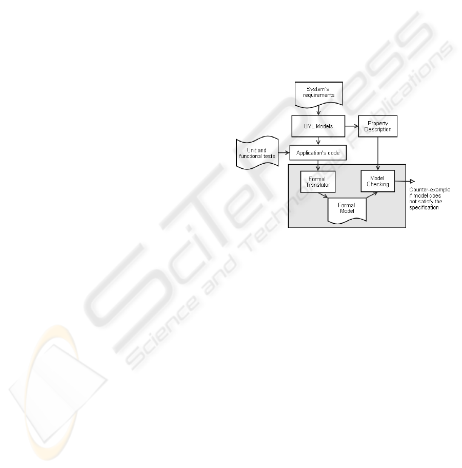
As depicted in Figure 1, this system design ap-
proach focuses on creating firstly the class, state ma-
chines, collaboration and sequence diagrams using
UML models. After that, the code could be generated
automatically in the language selected by the system
designer (e.g., SystemC, Java, and C/C++). As UML
models do not cover the full embedded system design
spectrum, then the test design techniques presented
further in Section 3.5 can be applied in order to (i)
help the system designer codify the system functions,
(ii) test the correctness and timeliness of the applica-
tion, and (iii) facilitate the verification activities de-
scribed in Section 3.6.
Figure 1: Test Design Approach.
From the application’s code, the formal transla-
tor converts it to a formal model (e.g., Communi-
cating Finite Automata or Petri Nets) with the pur-
pose of allowing the system designer to verify that
certain system’s properties hold in the model. The
system’s properties (e.g., deadlock-freeness, reach-
ability, safety and liveness) are expressed as state
formulae such as Linear Temporal Logic (LTL) and
Computation Temporal Logic (CTL). Furthermore, if
the model does not satisfy the specification then a
counter-example is generated which is included into
the test suite and after that it is used to test the appli-
cation’s code. The system’s properties can be verified
using the model checking kit developed by (Esparza
et al., 2008).
The product scope, time, quality, and costs pa-
rameters are monitored and controlled by the prod-
uct management processes group. These parameters
also influence the system platform and product de-
velopment processes groups. When the project starts
with an infeasible project plan which needs correc-
tive actions to be carried out then this processes group
aims to get the project back on the track and to en-
TOWARDS A SEMIFORMAL DEVELOPMENT METHODOLOGY FOR EMBEDDED SYSTEMS
7

sure that the project’s parameters are met. It is im-
portant to emphasize that the product management
and development processesgroups consist of the prac-
tices promoted by the XP and Scrum agile methods as
well as the agile patterns described in (Beck and An-
dres, 2004; Schwaber and Beedle, 2002; Coplien and
Schmidt, 2004).
The main reason to propose this semiformal de-
velopment methodology is to coverthe gaps identified
by (Abrahamsson et al., 2003; Ronkainen and Abra-
hamsson, 2003). Therefore, the main motivations of
the proposed methodology fall into the following cat-
egories: (i) full lifecycle coverage, (ii) project man-
agement activities, (iii) flexibility, (iv) means to ad-
dress the non-functional requirements, (v) a software
driven hardware development approach, (vi) concrete
guidance of the processes, and (vii) experimental re-
sults.
The next subsections are concerned with describ-
ing the roles and responsibilities, and the processes
lifecycle of the proposed methodology.
3.2 Roles and Responsibilities
The proposed methodology involves four different
roles and the responsibility of each role is described
as follows: Platform Owner is the person who is of-
ficially responsible for the products that derive from a
given platform. This person is responsible for defin-
ing quality, schedule and costs targets of the products.
Product leader is responsible for the implementa-
tion, integration and test of the product ensuring that
quality, schedule, and cost targets defined by the plat-
form owner are met.
FeatureLeader is responsible for managing, con-
trolling and coordinating subsystem projects, pre-
integration projects, external suppliers that contribute
to a defined set of features. Development Team
which may consist of programmers, architects, and
testers are responsible for working on the product de-
velopment.
If the product to be developed is small, i.e. it is
composed of few components (less than 50 KLOC)
and does not require other development teams to im-
plement the product’s functionalities then one product
leader and the development team are enough for the
product development. On the other hand, if the prod-
uct is composed by several components (more than
50 KLOC) and requires other development teams to
implement the product’s functionalities then the Fea-
ture Leader role must be involved in the processes. In
this context, one product leader requires feature lead-
ers to manage, control and coordinate components’
projects.
3.3 Processes Lifecycle
The proposed agile methodology consists of five
phases: Exploration, Planning, Development, Re-
lease, and Maintenance. In the Exploration phase,
the customers provide requirements for the product
releases. These requirements are included into the
product backlog by the platform owner in order to
estimate the effort with the product leader. In this
phase, the development team also identifies the plat-
form and application constraints and estimates the
system’s metrics based on the product backlog items.
With this information at hand, the development team
is able to define the system platform.
In the Planning phase, the platform owner and
customers identify more requirements and prioritize
the productbacklog. After that, the development team
spends one day to estimate the sprint backlog items
and decompose them into tasks. The tasks that make
up the sprint backlog must take from 1 to 16 hours to
be completed.
In the development phase, the team members im-
plement new functionalities and enhance the system
based on the items of the sprint backlog. The meet-
ings are held at the same time and place with the pur-
pose of monitoring and adapting the activities to pro-
duce the desired outcomes. At the end of each iter-
ation, unit and functional tests are executed and sys-
tem propertiesare checked in a continuous integration
build. System optimization also takes place during
this phase.
In the Release phase, the product is installed and
put into practical use. During this phase, it usually
involves the identification of errors and enhancement
in the system services. The Maintenance phase may
also require more sprints in order to implement new
features, enhancement and bug fixes raised in the re-
lease phase.
The next subsections describe only three pro-
cesses of the proposed methodology that focus on
achieving the system platform, testing and verifying
the system properties of the embedded systems. A de-
tailed description of the thirteen processes of our pro-
posed methodologyas well as processes templates are
public available for downloading at (Cordeiro, 2008).
3.4 Process for Instantiating the
Platform
This process would help us estimate the system met-
rics in order to define the system platform. To obtain
the execution time and energy consumption metrics,
we could specify the system’s functionalities in UML
by creating the class, state machines, collaboration
ENASE 2008 - International Conference on Evaluation of Novel Approaches to Software Engineering
8

and sequence diagrams. UML 2.0 profile could also
be used to specify the system functionalities (Kukkala
et al., 2005), but at the time we wrote this paper there
was no tool available to convert the UML 2.0 dia-
grams into a programming language.
The CASE (Computer Aided Software Engineer-
ing) tools like Together and Rational Rose could be
used for the entry of the system model. After speci-
fying the system model in UML using these tools, the
code could be generatedautomatically in the language
selected by the system designer (e.g., SystemC, Java,
and C/C++). Nguyen et. al. (Nguyen et al., 2004)
provides a tool that enables the system designer to
specify the system model in UML and automatically
convert it into SystemC code (Nguyen et al., 2004).
After generating the code in the selected language,
hardware/software estimation tools could be used to
estimate the system metrics. We could use the esti-
mation tool developed by our research group that is
capable of estimating the execution time and energy
consumption based on Assembly code (Oliveira Jr.
et al., 2006).
Therefore, after estimating the system’s met-
rics, we could provide this information to our hard-
ware/software partitioning tool. This tool allows the
user to (i) enter the system’s model, (ii) enter the ob-
jective function parameters such as metrics impor-
tance and constraints, (iii) select the components of
the system platform, and (iv) find the best partition
of the system. Therefore, our tool would look for
the best partitioning that meets the design constraints.
Since most design decisions are driven by constraints
then the application constraints should be incorpo-
rated into the objective function so that partitions that
meet constraints are considered better than those that
do not meet.
3.5 Process for Implementing New
System’s Functionalities
This process would support us for implementing the
system’s functionalities in a systematic way as well
as making the verification steps easier. According
to the business value of the system’s functionalities,
we could start writing the unit test for each stage of
computation for those requirements with high busi-
ness values. However, this kind of activity requires
certain level of experience from the system design-
ers. Nonetheless, they should successfully create and
compile the unit test before really writing the code
and verifying the system’s properties.
In order to test each computation stage of the sys-
tems’ functionalities, we could run the ESW on the
PC platform. We could use this approach through-
out the development cycle in order to avoid debug-
ging hardware and software simultaneously. By run-
ning the ESW on the PC platform, we could exercise
all code paths and gain confidence in the code before
running it on the target platform. Another way to gain
confidence in the code is to use the JTAG debug ca-
pability.
We could also create data files on the PC that have
all possible parameters combinations that make sense
for the system’s functions inputs. In this way, we
could provide these data to our unit tests to exercise
the code’s paths of the functions. The unit tests cre-
ated to the embedded products could be developed by
using the embUnit framework test tool (SourceForge,
2007b).
After that, we could run the ESW on the target
platform to verify the application’s timeliness. It is
importantto point out that for platform dependent and
indepedentcode, we could just separate them into dif-
ferent files in order to avoid using the #if and #else
statements throughout the code.
3.6 Process for Verifying System’s
Properties
The process for verifying the system’s properties al-
lows the system designer to check the system’s prop-
erties by making use of a verification technique called
model checking. Therefore, this process aims to ex-
haustively check all possible computations and ob-
serve if a program trace violates temporal and func-
tional properties. If the verification fails, then a path
that violates the specification (counter-example) is
produced and is later included into the test suite to
check the correctness of the system.
However, after converting the application’s code
into well-formed state machine models, the system
designer should then verify if (i) no machine has a
deadlock, (ii) no machine has nondeterminism behav-
ior, (iii) all outputs and inputs are used. All these
checks lead to verifying if local states are reach-
able to avoid dead code. Therefore, instead of try-
ing to enumerate a design’s reachable states, the sys-
tem designer should first create the state space us-
ing Boolean predicates that represent sets of states,
and Boolean variables that encode each local machine
state. In this way, given a set of states S, the reach-
ability problem could be summarized to determine
whether the state s ∈ S is reachable.
For it to take place, the system designer should
determine if S is reachable by constructing the set of
reachable states and then examine whether S inter-
sects this set. The model checking tool that supports
this process contributes to practical success because it
TOWARDS A SEMIFORMAL DEVELOPMENT METHODOLOGY FOR EMBEDDED SYSTEMS
9

checks from a fixed number of predefined properties
rather than requiring the system designer to choose
and formalize properties (Esparza et al., 2008). In or-
der to check properties that are specific to the domain
being observed, the system designer should then for-
malize these properties by using logics such as CTL
and LTL. Our final aim is to extract the information
about the system’s properties from the UML diagrams
and automatically verify them using the model check-
ing technique.
The next section describes the experimental re-
sults of our proposed methodology applied to the do-
mains of medical devices and embedded control sys-
tems.
4 EXPERIMENTAL RESULTS
In this section we present the results of our proposed
methodology applied to the development of the pulse
oximeter, digital soft-starter, and the induction mo-
tor simulator equipments. The pulse oximeter project
was slipt into 3 different sprints and developed by one
embedded system engineer. There was also a plat-
form owner who was responsible for defining quality,
schedule, costs and requirements of the product. The
digital soft-starter and motor simulator projects were
split into 2 different sprints and developedby four em-
bedded system engineers (each project had two engi-
neers), one product leader, and one platform owner.
At the beginning of the projects, we created a list
of new features and requirements in order to gather
all our needs (product backlog). Based on the busi-
ness value, we chose from the product backlog a set
of features and requirements to be implemented in the
projects’ iterations (sprint backlog). Therefore, we
put much emphasis on delivering the systems’ func-
tionalities with highest business value in the begin-
ning of the iterations. Delivering these functionalities
with highest business value, helped our customer and
platform owner get feedback on functionality earlier
and allowed them to spot any misunderstanding more
quickly. Table 1 shows the measured effort, busi-
ness value, and sprint velocity for each iteration of
the projects.
As can be seen in Table 1, the sprint velocity of
the pulse oximeter and soft-starter projects increased
as the systems were being developed. This situation
took place due to the fact that we were still learning
the involved technology, development environment,
and the application domain. On the other hand, the
sprint velocity of the motor simulator decreased due
to the fact that a team member was moved from the
soft-starter to another project. Therefore, the tasks
Table 1: Measured Effort (in hours).
IT1 IT2 IT3
Pulse Oximeter − − −
Measured Effort 128 127 63
Business value 22 27 16
Sprint Velocity 0.17 0.21 0.25
Digital Soft-Starter − − −
Measured Effort 70 84 −
Business value 11 16 −
Sprint Velocity 0.15 0.19 −
Motor Simulator − − −
Measured Effort 125 219 −
Business value 13 21 −
Sprint Velocity 0.10 0.09 −
that were allocated to him, had to be transferred to an
engineer of the induction motor simulator.
It is important to point out that we chose the pulse
oximeter as a case study because it was already de-
veloped in another work by our research group using
an ad hoc development methodology (Oliveira Jr.,
1998). After applying the proposed methodology, the
development time was decreased to 50% when com-
paring to this ad hoc development methodology. As
the proposed methodology does not cover the me-
chanical design of the product, then the same effort
needed by the ad hoc development methodology to
design the mechanical part was included into the pro-
posed methodology for comparison reasons.
On our embedded systems projects, we had plat-
form independent code and platform specific code.
For platform independent code, we applied our pro-
posed test techniques described in Section 3.5 which
check not only the logic but also the timing properties
in an automated way.
However, for platform specific code, we had to run
it on the target platform manually. For those soft-
ware classes that brought in sensor data, we just re-
placed for actual data when running on the PC. That
was much better than real data because we had the
opportunity to exercise all code paths and to validate
the correctness. When running the test cases against
these software classes automatically on the PC, we
only captured the outputs that would touch the hard-
ware and put them into the log file. Table 2 shows
the relationship between the test and code lines of the
projects.
The embedded software of our projects had to
run in a constrained environment. The development
platform used to develop these embedded products
had just 12KBytes of flash memory. Therefore, we
used the Big Visible Chart (BVC) proposed by (Beck
and Andres, 2004) with the purpose of tracking the
ENASE 2008 - International Conference on Evaluation of Novel Approaches to Software Engineering
10

Table 2: Total LOC (Application and Test).
Project Application Test
Pulse Oximeter 2685 1118
Digital Soft-Starter 1615 854
Motor Simulator 957 243
memory usage and power consumption metrics. Both
charts were regularly updatedand kept visible in order
to look for trends. Table 3 and 4 show the memory
usage and power dissipation values of the projects.
The current consumption was measured by connect-
ing a multimeter in series with the energy source. The
final power dissipation was then obtained by multi-
plying the current consumption by the supplied volt-
age. This power is dissipated in the whole system by
the digital and analog components.
Table 3: Memory Usage (Bytes).
Project RAM Flash
Pulse Oximeter 817 7711
Digital Soft-Starter 3631 3252
Motor Simulator 600 6398
Table 4: Power Dissipation (mW).
Project Power
Pulse Oximeter 414
Digital Soft-Starter 855
Motor Simulator 774
The test techniques described in Section 3.5 were
the suitable vehicle for software design and modular-
ity of the pulse oximeter, digital soft-stater and motor
simulator embedded software. The final solutions of
these equipments have approximately 80, 35 and 31
functions in C code respectively. All projects’ sprints
were analyzed and the result was an average cyclo-
matic complexity of 3.15, 1.43 and 1.61 at the end of
the sprints.
The average cyclomatic complexity (v(G)) of the
systems measures the complexity of a module’s de-
cision structure and indicates the number of linearly
independent paths. Therefore, these low cyclomatic
complexity levels make the white-box testing easier
due to the fact that they decrease substantially the
number of paths that should be tested to reasonably
guard against errors. Data on source code size, num-
ber of functions and cyclomatic complexity were ob-
tained using CCCC tool which analyzes C/C++ files
(SourceForge, 2007a).
The proposed methodology has partially been ap-
plied to a multi-site software project in the area of
telecommunication containing more than 300 KLOC
and involving four different development companies.
The results obtained by applying a subset of the
processes in this multi-site project can be found at
(Cordeiro et al., 2007). The next section concludes
this work and provides goals for future research.
5 CONCLUSIONS AND FUTURE
WORK
This paper described an embedded system develop-
ment methodology and its application in the devel-
opment of the pulse oximeter, digital soft-starter and
induction motor simulator equipments. In these case
studies, the development platform reduced substan-
tially development time of the product. Specifically,
for the pulse oximeter case study, we reduced the de-
velopment time to 50% when compared to an ad hoc
development methodology.
In addition,we also applieda set of test techniques
in order to guarantee the timeliness and correctness
of the embedded software. These test techniques led
to better software design and modularity. Therefore,
we obtained 3.15, 1.43, and 1.61 average cyclomatic
complexity levels for the pulse oximeter, digital soft-
starter and motor simulator equipments respectively.
For further steps, we are researching models that can
carry enough information about the physical imple-
mentation and achieve better results in terms of func-
tional correctness.
It is important to point out that development
methodologies are very difficult to compare, mainly
because they depend on people’s pride in their work,
wanting to be part of a team, and willingness to
pitch in. In order to effectively compare develop-
ment methodologies, a statistical analysis must be
carried out to provide actual results in terms of pro-
ductivity gains. Therefore, we are planning to per-
form more experimental studies where the methodol-
ogy will be observed while applied in different devel-
opment teams.
ACKNOWLEDGEMENTS
The authors would like to thank the students Carlos
Mar, Eduardo Valentin, Fabiano Teixeira, and Daniel
Patrick for the dedication and motivation to accom-
plish two case studies and also Petrina Kimura for the
implementationof the partitioningalgorithms. We are
very grateful to the support received from the Science
TOWARDS A SEMIFORMAL DEVELOPMENT METHODOLOGY FOR EMBEDDED SYSTEMS
11

and Technology Center forthe IndustrialPole of Man-
aus and the Brazilian Council for Scientific and Tech-
nological Development (CNPq) by its partial financial
support through project 553164/2005-8.
REFERENCES
Abrahamsson, P., Warsta, J., Siponen, M., and Ronkainen,
J. (2003). New directions on agile methods: A com-
parative analysis. Proceedings of the 25th Interna-
tional Conference on Software Engineering, Portland,
Oregon, USA, IEEE Computer Society, pages 244–
254.
Beck, K. and Andres, C. (2004). Extreme Programming Ex-
plained - Embrace Change. Second Edition, Addison-
Wesley.
Chateau, J. M. (2001). Flexible platform-based design. On-
line Resources for comms design engineers. Available
at http://www.commsdesign.com. Last visit on 14th
January 2008.
Coplien, J. O. and Schmidt, D. (2004). Organizational Pat-
terns of Agile Software Development. First Edition,
Prentice Hall.
Cordeiro, L. (2008). Txm: Uma metodologia de desen-
volvimento de hw/sw para sistemas embarcados.
A thesis presented at the Federal University of
Amazonas in partial fulfillment of requirements
for the degree of Master of Science. Available
at http://www.dcc.ufam.edu.br/ lcc/resume.html
(In Portuguese) and
http://www.dcc.ufam.edu.br/ lcc/methodology (In
English).
Cordeiro, L., Becker, C. O., and Barreto, R. S. (2007). Ap-
plying scrum and organizational patterns to multi site
software development. In 6th Latin American Con-
ference on Pattern Languages of Programming, 2007,
Porto de Galinhas, Brazil. SugarLoafPlop’07, pages
46–67.
Dowty, M. (2004). Test driven development of embed-
ded systems using existing software test infrastruc-
ture. Available at http://embunit.sourceforge.net/. Last
visit on 27th December 2007.
Esparza, J., Schrter, C., and Schwoon, S. (2008). Model-
Checking Kit. Published at the University of
Stuttgart in the Institute of Formal Methods in
Computer Science, Available at http://www.fmi.uni-
stuttgart.de/szs/tools/mckit/. Last visit on 14th Jan-
uary 2008.
Gajski, D., Zhu, J., Dmer, R., Gerstlauer, A., and Zhao, S.
(2000). Specc: Specification language and method-
ology. Kluwer Academic Publishers, Boston, March
2000.
Greene, B. (2004). Agile methods applied to embedded
software development. Proceeding of the Agile De-
velopment Conference (ADC’04).
Kimura, P., Barreto, R. S., and Cordeiro, L. C. (2007).
Projeto e Implementao de um Plug-in Baseado no
Framework do OSGi para Particionamento de Hard-
ware/Software (In Portuguese). Trabalho de Iniciao
Cientfica. Universidade Federal do Amazonas. Con-
selho Nacional de Desenvolvimento Cientfico e Tec-
nolgico.
Koss, R. and Langr, J. (2002). Test driven development in c.
Available at http://embunit.sourceforge.net/. Last visit
on 27th December 2007.
Kukkala, P., Riihimki, J., Hnnikinen, M., Hmlinen, T., and
Kronlf, K. (2005). Uml 2.0 profile for embedded
system design. Proceedings of the Design, Automa-
tion and Test in Europe Conference and Exhibition
(DATE’05).
Manhart, P. and Schneider, K. (2004). Breaking the ice for
agile development of embedded software: An indus-
try experience report. Proceedings of the26th Interna-
tional Conference on Software Engineering (ICSE04),
page 3647.
Nguyen, K., Sun, Z., , and Thiagarajan, P. (2004). Model-
driven soc design via executable uml to systemc. Pro-
ceedings of the 25th IEEE International Symposium
on Real-Time Systems, Page(s) 459-468, pages 459–
468.
Oliveira Jr., M. (1998). Desenvolvimento de Um Prot´otipo
para a Medida N˜ao Invasiva da Saturac¸˜ao Arterial de
Oxigˆenio em Humanos - Ox´ımetro de Pulso (In Por-
tuguese). Master thesis, Center for Informatics at Fed-
eral University of Pernambuco.
Oliveira Jr., M., Neto, S., Maciel, P., Lima, R., Ribeiro, A.,
Barreto, R., Tavares, E., and Braga, F. (2006). Ana-
lyzing software performance and energy consumption
of embedded systems by probabilistic modeling: An
approach based on coloured petri nets. ICATPN 2006,
LNCS 4024, pp. 261281, 2006., page 261281.
Ronkainen, J. and Abrahamsson, P. (2003). Software de-
velopment under stringent hardware constraints: Do
agile methods have a chance? eXtreme Programming
Conference.
Schooenderwoert, N. V. and Morsicato, N. (2004). Taming
the embedded tiger - agile test techniques for embed-
ded software. Proceedings of the Agile Development
Conference (ADC’04).
Schwaber, K. and Beedle, M. (2002). Agile Software De-
velopment with Scrum. First Edition, Series in Agile
Software Development, Prentice Hall.
SourceForge (2007a). C and C++ Code Counter. Avail-
able at http://sourceforge.net/projects/cccc. Last visit
on 18th October.
SourceForge (2007b). embUnit: Unit Test Frame-
work for Embedded C Systems. Available at
http://embunit.sourceforge.net/. Last visit on 18th Oc-
tober.
Vicentelli, A. S. (2002). Platform-based design. EEDesign
of EETimes.
ENASE 2008 - International Conference on Evaluation of Novel Approaches to Software Engineering
12
