
WORKFLOW AUTOMATION FOR SYSTEM ARCHITECTING
Markku Turunen, Kari Lepp¨anen
Nokia Research Center, P.O. Box 407, FI-00045 Nokia Group, Finland
Sari Lepp¨anen
Nokia Corporation, P.O. Box 407, FI-00045 Nokia Group, Finland
Keywords:
Automated systems architecting, Model-based design, Executable specifications, UML 2.0.
Abstract:
Managing the ever-growing complexity of even mass-market products, such as mobile phones, is becoming
increasingly hard without the adoption of improved system development methods, such as model-based de-
velopment. To allow industrial use of such methods, tools that are able automate development tasks as far
as possible are needed. In this paper, we present a partly automated system design flow based on the Lyra
method with UML 2.0 language and Telelogic Tau G2 modeling tool. We discuss how the tool was extended
to support automation of some central tasks in Lyra and show a running example of the design flow. In the
example, a telephony functionality of a mobile device is modeled producing an executable specification for
the system. The efficiency gains from the automation are promising.
1 INTRODUCTION
The rapidly increasing size and complexity of indus-
trial software systems, and the tightening competi-
tion in the markets calls for novel and more efficient
system development approaches. Model-based de-
velopment and model-driven architectures, or MDA
(OMG, 2005a) have become the main stream solu-
tions in the pursuit of novel systems engineering ap-
proaches. They provide the basis for the definition
of specialized development methods (e.g. for a do-
main or company) covering possibly several phases
in the whole system development process. Adoption
of the MDA approach into a specialized industrial de-
velopment process allows high degree of automation
in various development phases.
The system design flow automation proposed in
this paper is built on a systematic domain-specific de-
sign method, called the Lyra method (see for example
(Lepp¨anen, 2005)). It adopts the ideas of model-based
development and MDA, and combines them with the
prevailing system and architecture design practices in
the domain of communicating distributed systems and
within Nokia. The specification of the system behav-
ior, which is the primary source for the overall sys-
tem complexity, is central in Lyra. Process algebraic
thinking and specification style is an inherent part of
the method. Indeed, the primary motivation for the
development of the Lyra method has been bridging
the gap between the industrial system design and for-
mal methods. This differentiates Lyra from e.g. the
ROOM method (Selic et al., 1992), which, at first
glance, has many similarities. Formal methods al-
low verification of system specification from day one
of development. They make it possible to enforce
conformance between specification and implementa-
tion by running an implemented component against
its specification (for example, ROOM maintains the
consistency between specification and implementa-
tion through automatic code generation). They also
create a basis for automation, both inside the system
design flow and between various development tasks,
such as design, testing and verification (Schulz et al.,
2007), system analysis, and documentation. Together,
such design automation and systematic testing dur-
ing the whole development process have the poten-
tial to significantly reduce the total effort required to
developcomplex systems, as well as improve the soft-
ware quality.
The industrial trials for the Lyra method have in-
dicated that a systematic and simple design flow to-
gether with a high degree of automation are required
and possible (Honkola et al., 2007)(Lepp¨anen et al.,
2007) for industrial usage. In order to use the devel-
oped system models at various levels of abstraction in
the later phases of development, the models have to
be rigorously and systematically defined and contain
sufficient amount of information. In the traditional
39
Turunen M., Leppänen K. and Leppänen S. (2008).
WORKFLOW AUTOMATION FOR SYSTEM ARCHITECTING.
In Proceedings of the Third International Conference on Evaluation of Novel Approaches to Software Engineering, pages 39-46
DOI: 10.5220/0001761700390046
Copyright
c
SciTePress

way, system architectures and high-level functionali-
ties are defined using mainly informal drawings and
text, which do not support automation, nor provide
direct input for other development phases, like verifi-
cation and testing. Behavior is usually not considered
until in the implementation phase.
Clearly, more rigorous descriptions of the system
structure and behavior in the early phases of devel-
opment mean transferring effort from the implemen-
tation into the system specification. However, only
the essential information is specified and refinement
of details is still left for further steps during design
and implementation.
In this paper we present a system design automa-
tion approach developed in industrial settings. It is
based on the Lyra design method and implemented
using UML 2.0 language (OMG, 2005b) and the Tele-
logic Tau tool (Telelogic, 2007). Note that the Lyra
method per se is language and tool independent. The
paper is organized as follows: Section 2 gives an
overview of the central Lyra modeling concepts for
systems architecting and design. These concepts are
used in the automation approach, which is described
and illustrated with a running example in section 3.
Section 4 discusses experiences with this new frame-
work, as well as current and future work in areas re-
quiring improvement. Finally, conclusions are drawn
in section 5.
2 THE LYRA METHOD
Lyra has been developed in Nokia Research Cen-
ter in 1997-2007 as an exemplary system develop-
ment method in order to show that formal methods
can already now be successfully applied in industrial-
strength system development. It describes a con-
crete flow to specify and model systems using the
principles of stepwise refinement and correct-by-
construction. It has been designed to provide the
”glue” between the methods and thinking of indus-
trial system designers and architects on one hand, and
the underlying formal techniques on the other. Lyra is
especially suitable for designing distributed reactive
systems utilizing asynchronous communication, such
as control of telecommunication networks. It allows
both top-down and compositional approach to system
development.
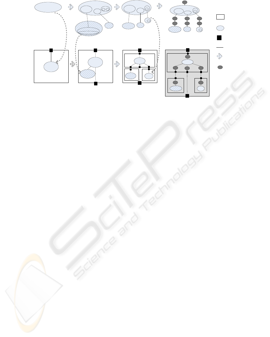
The concept of service, used to encapsulate func-
tionality, is central in Lyra: the core flow of Lyra
focuses on the definition of services. For any given
service there are four consecutive phases: specifica-
tion, decomposition, distribution and implementation
(See the top of Figure 1). Each phase produces a re-
fined specification for the service that has enough in-
formation for execution. For a more detailed account
of Lyra, see (Lepp¨anen, 2005) or (Lepp¨anen et al.,
2007).
Service Specification (SSp). The purpose of this first
phase is to specify the valid behavior of a service as
observed by the users of that service, or PSAP Com-
munication behavior (the service communicates with
its user via Provided Service Access Point or PSAP).
The valid externally observable behavior consists of
both static definition of the service interfaces and dy-
namic behavioral specifications. The internal func-
tionality to implement the externally observable be-
havior is not specified; rather, it is abstracted mod-
eling nondeterminism in such a way that already the
service specification model is executable.
Service Decomposition (SDe). This phase specifies
how the externally observable behavior of a service
is realised by internal functionality. Here the ser-
vice is iteratively decomposed into more refined ser-
vice components, until a desired level of atomicity is
reached. The execution order and logic for the ser-
vice components occurs through Execution Control
behavioral specification. If the service uses exter-
nal services to implement its own behavior towards
its user(s), then the external behavior required to use
such services is specified. This behavior, which is vis-
ible on Used Service Access Points, is called USAP
Communicationbehavior. The specification of behav-
ior has a clear hierarchy in Lyra: PSAP Communica-
tion (top), Execution Control and Internal Computa-
tion (middle), USAP Communication (bottom).
Service Distribution (SDi). This phase specifies how
the service is distributed into the (logical) nodes of the
system platform. From the modeling point of view,
the system platform can be understood as the set of
subsystems that comprise the system. Both the func-
tional split and the resulting peer communication are
specified in an executable manner.
Service Implementation (SI). The outcomes of the
previous phases are independentof the underlying im-
plementation technology. For example, the specified
communication between services is virtual. This final
phase specifies how the specification of virtual com-
munication of the service is mapped into a specifica-
tion of real communicationused in the selected imple-
mentation technology, whether that is simple function
call API between software modules, an adaptation to
a software message bus or serialization of messages
and sending them on top of a transport service like
TCP/IP.
The previous phases are iteratively run on each
service to specify the system functionality. The sys-
tem structure, on the other hand, is specified using
ENASE 2008 - International Conference on Evaluation of Novel Approaches to Software Engineering
40
Phone
Phone
Telephony
Phone
System
component
Service
component
SAP (Service
Access point)
Communication
channel
Service specification Service decomposition
Service distribution
...
Service implementation
Model
refinement
Service
adaptation
Phone
System interface
specification
System functional
architecture
System architecture
...
TelephonyControl
Phone
...
System architecture (with
realized communication)
...
Telephony
Telephony
Telephony
Phone
Create
Call
Telephony
Phone
Uses Uses
...
...
CallEstablishment
Create
Call
...
...
...
Mobile Device
Mobile Device
Mobile Device
Phone
...
Telephony
Create
Call
...
...
...
Service
refinement
flow
System
refinement
flow
Application Engine Application Engine
Wireless Modem
Wireless Modem
Figure 1: Lyra phases.
the concept of system component. They encapsulate
services and define clear interfaces between differ-
ent parts of the system through SAPs (Service Access
Points). A system component can have three parallel
specifications: SIS, SFA and SA (See the bottom of
Figure 1).
System Interface Specification (SIS). For a given
system component, SIS specifies the interfaces and
their external behavior as observed by other systems
(or users of the system, which often are also systems).
This specification is necessary for integrating a sys-
tem component with the surrounding systems and is
usually given as input to the team responsible for the
further developmentof a given system. The externally
observable behavior is specified by a set of services
within the system component. SIS is an executable
model of the system that does not specify its internal
structure or functionality. The executability requires,
though, that the internal functionality has to be mod-
eled to some extent as a set of executable services.
System Functional Architecture (SFA). SFA spec-
ifies the internal functionality of a system compo-
nent as a set of system services and their inter-
communication. These services are based on the ser-
vices used in SIS, but extended and further refined.
The externally observable behavior of the SFA shall
be equal to that of the SIS. SFA does not define which
are the subsystems of this particular system compo-
nent or how the internal functionality is distributed
into them. Rather, it is purely an executable specifi-
cation of the system functionality.
System Architecture (SA). The third definition for a
system component is needed when the system com-
ponent itself consists of (sub)systems. System Archi-
tecture (SA) defines formally how the system is com-
posed of its subsystems and how the subsystems are
interfaced. Whereas SIS and SFA are compositions
of service components, SA is a composition of sys-
tem components. It is the formal SA that allows re-
cursion (top-down mode of development) in system
design and ties together all system specifications at
different layers of abstraction. It also allows systems
to be built from existing and tested system compo-
nents (compositional mode of development).
3 AUTOMATION FRAMEWORK
In this section we present the automated system de-
sign flow starting from a logical view and ending with
a functional specification for a software design. We
use the MobileDevice system as a running example.
The MobileDevice provides a Phone service for its
users. The service includes capabilities to select a
phone number from a phone book, to make a call and
to end a call.
3.1 Mapping of Modeling Concepts
The core modeling concepts of Lyra have been ini-
tially defined as a UML 2.0 profile (Lepp¨anen et al.,
2005)(Lepp¨anen, 2005). A single Lyra concept can
be expressed with several different UML 2.0 language
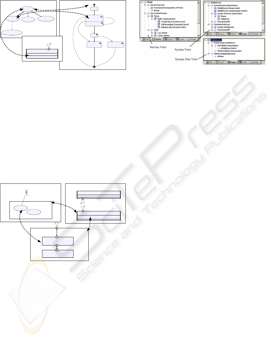
elements. For example, the service Phone and its ser-
vice component CreateCall are expressed as stereo-
typed use cases in the Functional Decomposition di-
agram (a stereotyped use case diagram) of the ser-
vice; see Figure 2. The service interfaces of Phone are
shown in a class diagram where Phone is expressed as
a class. The PSAP Communication behavior of Phone
is specified in a stereotyped state machine diagram.
There the service component CreateCall is expressed
as a composite state.
WORKFLOW AUTOMATION FOR SYSTEM ARCHITECTING
41
Functional Decomposition of Phone
Phone
<<ServiceComponent>>
CreateCall
<< ServiceComponent>>
ReleaseCall
<<ServiceComponent>>
CallTerminated
<< ServiceComponent>>
xp_
done
xp_
done
Idle
create_call_req
(v.phone.createCallReq)
CreateCall
););
CallCreated
CallTerminatedReleaseCall
CreateCall viaep_calling
Signature
active class Phone
<< ServiceComponent>>
::Phone ::ServiceSpecification:: Phone
PSAPPSAP
I_to_PhoneI_from_Phone
PSAP Communication of Phone state PSAPCommunication
<< include>>
<< include>>
<< include>>
<<uses>>
[xp_calling]
/^calling_ind(v.phone.callingInd);
[xp_call_created]
/^create_call_cnfv.phone.createCallCnf);
[xp_terminated]
[xp_terminated]
/^call_terminated_ind
(v.phone.callTerminatedInd);
[xp_released]
/^call_released_cnf
(v.phone.callReleasedCnf);
release_call_req
(v.phone.releaseCallReq)
release_call_req
(v.phone.releaseCallReq)
[xp_call_not_created]
/^create_call_fail_cnf
(v.phone.createCallFailCnf);
CallEstablishment
<< ServiceComponent>>
Figure 2: Example UML representations for services and
service components.
Mapping of the structural Lyra concepts, e.g. Sys-
tem and System Component, to UML 2.0 is similar to
that of functional concepts, see Figure 3. An overview
of the system MobileDevice is expressed using the
Domain Model diagram (a stereotyped use case di-
agram), which shows the users and the system ser-
vices. The System Functional Architecture diagram
(a stereotyped composite structure diagram) shows
the system and system services in more detailed fash-
ion whereas the Communication Context diagram (a
stereotyped class diagram) concentrates on the sys-
tem interfaces and the external entities communicat-
ing with the system.
MobileDevice Domain model
<<
SystemInterfaceSpecification >> package
SystemFunctionalArchitecture
aMobileDevice :
MobileDevice
aUser : MobileDeviceUser
Phone
<<ServiceComponent >>
Telephony
<<ServiceComponent>>
Communication context
<<
SystemInterfaceSpecification>> package
SystemInterfaceSpecification
<<SystemComponent>>
MobileDevice
DeviceUserSAP
I_to_MobileDeviceI_from_MobileDevice
::MobileDevice :: ExternalEntities ::MobileDeviceUser
USAPUSAP
I_from_MobileDeviceI_from_MobileDevice I_to_MobileDeviceI_to_MobileDevice
System Functional Architecture
active <<SystemComponent >>class
MobileDevice
DeviceUserSAPDeviceUserSAP
I_to_MobileDeviceI_from_MobileDevice
<<Servic eComponent>>
aPhone
:
Phone
PSAPPSAP
TelephonyControlUSAPTelephonyControlUSAP
<<ServiceComponent>>
aTelephony: Telephony
PSAPPSAP
Figure 3: Example UML representations for systems and its
components.
3.2 Model Views
In order to improve visibility of the Lyra concepts,
the Tau tool was extended with Lyra specific views.
They show model elements grouped according to the
relationships between the Lyra concepts. The Service
View (Figure 4) shows the service components and
the outcomes of their refinement phases. The Sys-
tem View shows all the three possible specifications
(SIS, SFA and SA) for the system components. Fi-
nally, the System Tree view shows the system struc-
ture, i.e. the hierarchical decomposition of the system
into (sub)systems, as a tree.
Figure 4: Lyra Views.
3.3 System Design Flow Automation
The previous trials ((Honkola et al., 2007)(Lepp¨anen
et al., 2007)) have shown that the Lyra method was
perceived as an efficient way of solving the chal-
lenge of designing complex systems. The main ob-
stacle preventing immediate large-scale adoption was
related to the tools and lack of automation. Construc-
tion of Lyra UML 2.0 models manually is quite te-
dious, since already a few instances of Lyra concepts
generate a large amount of UML 2.0 model elements.
This creates the impression of great complexity for
the designers. To overcome this problem a set of wiz-
ards was created. They create instances of the Lyra
concepts and thus move focus from the creation of
various UML 2.0 model elements to the actual design
flow and to the information that is essential in the sys-
tem architecture and design.
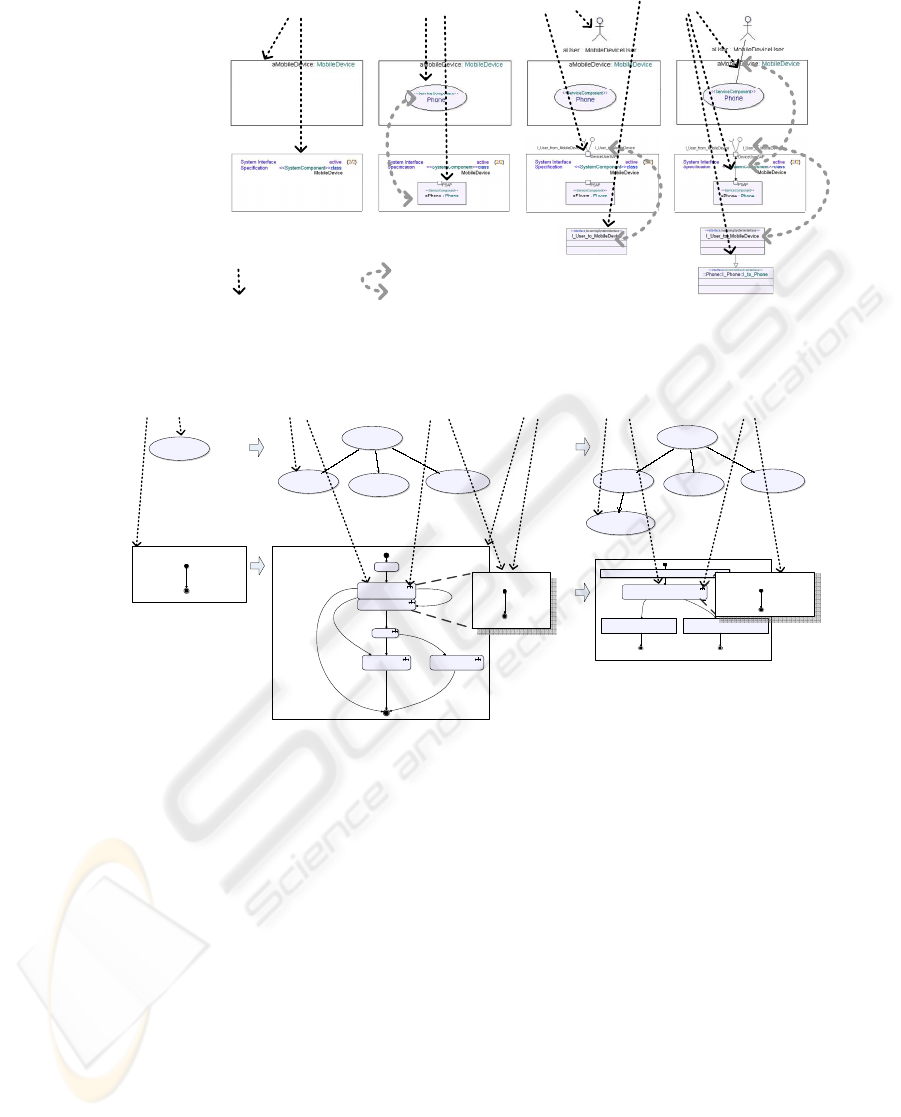
3.3.1 System Interface Specification, Service
Specification
Creation of the system model starts with the creation
of a SIS for MobileDevice. The New System Interface
Specification wizard creates a skeleton definition for
the new system comprising several packages that con-
tain model elements and Lyra specific diagrams, see
Figure 5.
For the Phone service, there must be a Service
Specification (SSp). The wizard New Service Spec-
ification creates a skeleton definition for a service,
including a stereotyped use case definition, a stereo-
typed class definition with an empty state machine
and interface defintions, see Figure 6. During the Ser-
vice Specification phase, the functional decomposi-
tion of the Phone service proceeds to the level that is
enough for PSAP communication, i.e. only those ser-
vice components that are relevant for the externally
observable behavior are specified. The wizard New
Service Component creates new stereotyped use case
definitions and state definitions for the new service
components like CreateCall, see Figure 6. The wiz-
ard New Execution Control state machine makes the
ENASE 2008 - International Conference on Evaluation of Novel Approaches to Software Engineering
42
System Interface
Specification diagram
refinement
Domain Model diagram
refinement
New System
Service wizard
System interface
refinement
New System Interface
Specification wizard
New System Service
Usage wizard
New System User
wizard
X creates Y
X
Y
X
Two UML representations for a
Lyra concept instance XX
Figure 5: SIS Flow.
CreateCall
<<ServiceComponent >>
ReleaseCall
<<ServiceComponent >>
CallTerminated
<< ServiceComponent>>
<<include>>
Functional
decomposition
Refinement of
PSAP
Communication ,
Execution
Control and
USAP
Communication
of Phone
New Service
Component
wizard
New Execution
Control State
machine wizard
PSAP Communication
of Phone
state
PSAPCommunication
xp_
done
<<include>>
<<include>>
Phone
<<ServiceComponent >>
Phone
<<ServiceComponent >>
New Service
Specification
wizard
xp_
call_
created
d.MakeCallEstablishmentReq();
CallEstablishment
[xp_call_establishment_success]
[xp_call_establishment_failure]
d.SaveCallEstablishmentCnf();
Execution control
state CreateCall
d.SaveCallEstablishmentFailCnf();
xp_
call_
not_
created
CreateCall
<<ServiceComponent >>
ReleaseCall
<<ServiceComponent >>
CallTerminated
<< ServiceComponent>>
<<include>>
<<include>>
<<include>>
Phone
<<ServiceComponent >>
CallEstablishment
<<ServiceComponent >>
<<uses>>
New Service
Component
wizard
New USAP
Communication State
machine wizard
done
done
xp_xp_
Idle
create_call_req
(v.phone.createCallReq)
CreateCall
CallCreated
CreateCallvia ep_calling
PSAP Communication of Phone state PSAPCommunication
[xp_calling]
/^calling_ind
(v.phone.callingInd);
[xp_call_created]
/^create_call_cnfv.phone.createCallCnf);
[xp_terminated]
[xp_terminated]
/^call_terminated_ind
(v.phone.callTerminatedInd);
[xp_released]
/^call_released_cnf
(v.phone.callReleasedCnf);
release_call_req
(v.phone.releaseCallReq)
release_call_req
(v.phone.releaseCallReq)
[xp_call_not_created]
/^create_call_fail_cnf
(v.phone.createCallFailCnf);
););
CallTerminatedReleaseCall
New Service
Decomposition
wizard
New model
elements
for SDe
USAP
Communication
state
CallEstablishment
xp_
default
Execution
control
state
CreateCall
xp_
default
Skeleton state machine for
PSAP Communication
Skeleton state
machine for
Execution Control
of CreateCall
Skeleton
state
machine
for USAP
Comm.
Manually refined state machine for PSAP Comm.
Manually refined state machine for
Execution Control of CreateCall
Figure 6: SSp flow and SDe flow.
created states hierarchical and adds a skeleton execu-
tion control state machine. What is left for the de-
signer is to complete the specification of behavior by
adding transitions between the states.
The system component design flow can proceed
in parallel with the service flow. Figure 5 illustrates
this. To bind the created service to the system we use
the New System Service wizard. The wizard New Sys-
tem User is used to specify different user types of a
system and the SAPs and system interfaces via which
the system communicates with them. Finally the wiz-
ard New Service Usage binds a system user, a system
service and the SAPs, and thus completes the SIS.
3.3.2 Service Decomposition
The Phone service (functionality) is refined during
the Service Decomposition (SDe) phase. There is an-
other service within MobileDevice, Telephony, that is
used by Phone. During refinement it is specified how
Phone uses the service provided by Telephony. How
another service is used shall not affect service spec-
ification. Therefore, the New Service Decomposition
wizard creates new model elements for the SDe phase
leaving the SSp phase definitions intact. The New Ser-
vice Component wizard and the New USAP Commu-
nication wizard create new service component states
and new sub state machines for specifying communi-
cation towards the used service, see Figure 6.
3.3.3 System Functional Architecture
Services that are internal to a system (not visible to
the system users) are bound to the system with the
SFA. The New System Functional Architecture wizard
creates new SFA phase specific model elements for
the MobileDevice system leaving the SIS definitions
intact, see Figure 7. The version of the Phone ser-
WORKFLOW AUTOMATION FOR SYSTEM ARCHITECTING
43
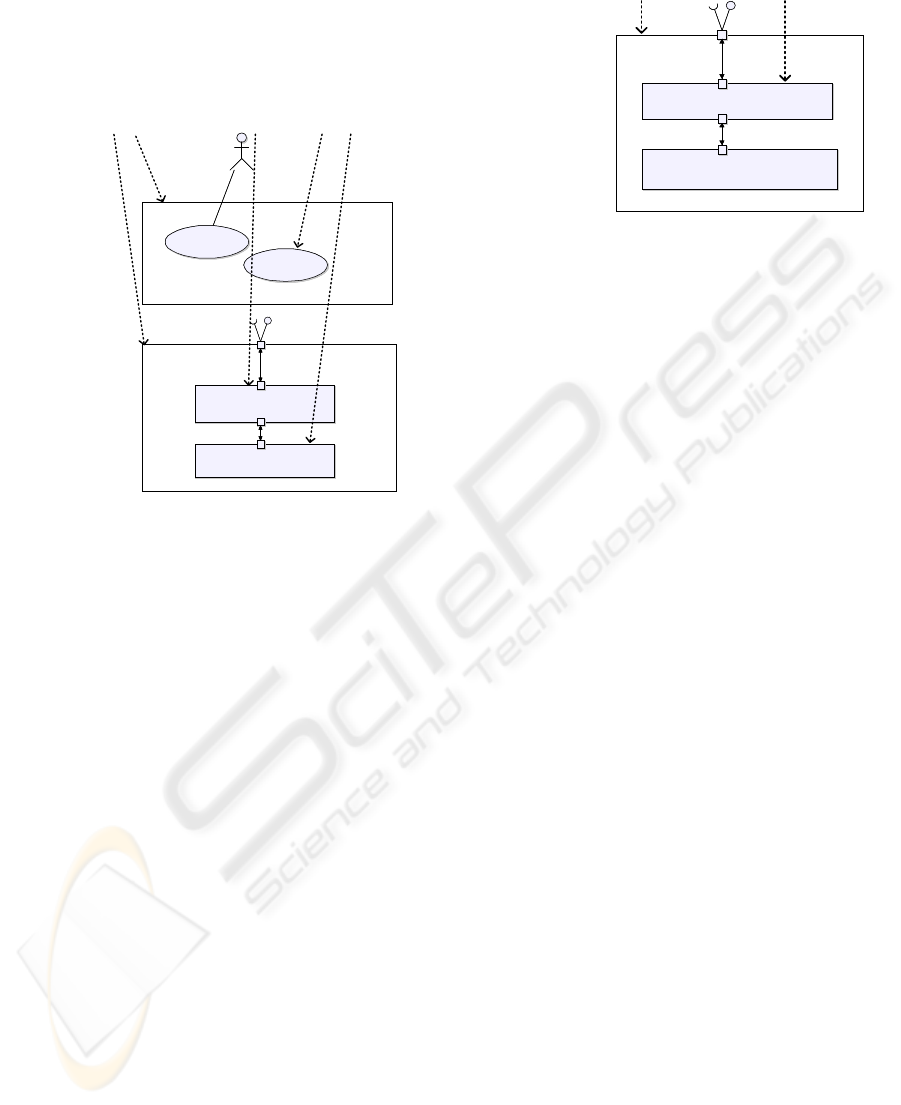
vice component in SFA shall be SDe instead of SSp.
The Update Service Component part wizard updates
the used version by changing the class of the attribute.
Finally the New System Service wizard binds the Tele-
phony service as a system service.
aMobileDevice : MobileDevice
aUser : MobileDeviceUser
Phone
<<ServiceComponent>>
Telephony
<<ServiceComponent>>
aMobileDevice : MobileDevice
aUser : MobileDeviceUser
Phone
<<ServiceComponent>>
Telephony
<<ServiceComponent>>
System Functional Architecture active <<SystemComponent >>class
MobileDevice
DeviceUserSAPDeviceUserSAP
I_User_to_MobileDeviceI_User_to_MobileDeviceI_User_from_MobileDeviceI_User_from_MobileDevice
<<ServiceComponent>>
aPhone : Phone
PSAPPSAP
TelephonyControlUSAPTelephonyControlUSAP
<<ServiceComponent>>
aTelephony : Telephony
PSAPPSAP
New System Functional
Architecture wizard
New System
Service wizard
System Functional
Architecture diagram
refinement
Domain Model
diagram refinement
Update Service
Component part
wizard
New model
elements
for SFA
SDe
specific
version
Figure 7: SFA flow.
3.3.4 System Architecture, Service Distribution
Whereas the SFA specifies all the functionalities con-
tained in the MobileDevice, the SA of MobileDevice
specifies its internal structure (subsystems). The New
System Architecture wizard creates new SA phase
specific model elements for MobileDevice leaving the
SFA definitions intact. Creation of SIS for the new
system components starts a new system component
design recursion round (see 3.3.1)). The Phone ser-
vice is specified as the system service of the Applica-
tion Engine system component (See Figure 1), and the
Telephony service as the system service of the Wire-
less Modem system component. The New Subsystem
wizard binds the created system components to the
system, see Figure 8.
In this example, there was no need for a Service
Distribution phase for either service as the deploy-
ment of services into system components was done
on service boundary. When there are several system
design recursion rounds resulting nested system com-
ponents it is typical that a single service of the orig-
inal system is distributed into multiple system com-
ponents during later recursion rounds. In such a case,
the Service Distribution phase produces the (service-
specific) communication protocol specifications for
the interfaces between the system components con-
taining parts of the service. The New Service Distri-
bution wizard has the capability to produce the initial
System Architecture active
<<SystemComponent >>class
MobileDevice
DeviceUserSAPDeviceUserSAP
I_User_to_MobileDeviceI_User_to_MobileDeviceI_User_from_MobileDeviceI_User_from_MobileDevice
<<SystemComponent>>
theApplicationEngine :ApplicationEngine
<<SystemComponent>>
theWirelessModem :WirelessModem
APE_SAPAPE_SAP
WM_SAPWM_SAP
DeviceUser_SAPDeviceUser_SAP
System Architecture
diagram refinement
New System
Architecture wizard
New Subsystem
wizard
New model
elements
for SA
Figure 8: SA flow.
decomposition of a service as distributed services in
cases when the main Execution Control of a service
remains in one service component. That is not shown
in this paper.
3.3.5 System Architecture, Service
Implementation
So far, the specification for MobileDevice has been at
implementation and platform independent level. Next
we show how these specifications are mapped to im-
plementation specifications.
Construction of implementation specific System
Architecture for MobileDevice is the same as pre-
sented in 3.3.4. The New System Architecture wiz-
ard creates new model elements for a new implemen-
tation specific system component design phase. The
previous implementation independent SA definitions
are left intact.
The SIS for implementation specific system com-
ponents contains the original services and service
adaptions for the services. The service adaptations
are the result of the Service Implementation phase.
The Service Implementationphase deals with only
one issue: how the PSAP and USAP communications
are realised in terms of implementation platform con-
cepts. Such service adaptation varies a lot. The sim-
plest case is when the signal exchange of PSAP com-
munication is mapped directly to function calls. More
complex cases handle distribution of service compo-
nents into different processes that may run in differ-
ent processors and even in different devices. Service
adaptation in such cases deals with how to use plat-
form specific services in order to to realise the com-
munication between the service components.
Currently, no automation for the Service Imple-
mentation phase is available. However automation
can be implemented for selected target platforms and
design patterns. Generation of C++ APIs and/or D-
Bus interfaces are likely to be the first candidates for
automation.
ENASE 2008 - International Conference on Evaluation of Novel Approaches to Software Engineering
44

As a result of this phase, we have an executable
specification of the valid externally observable be-
havior for the system components that are going to
implement the Phone and Telephony functionalities.
3.3.6 Executable Models
By model execution we mean capability to run the
specified behavior in a simulator. Construction of a
simulator for a system is simple when using the New
System Simulator wizard. One has to select from
what refinement phase the simulator is to be con-
structed. The wizard then collects all the referenced
system components and service components. If there
are several refinement versions for a system compo-
nent, the wizard asks what refinement version is to be
used. It proceeds to create a copy of all the needed
model elements, at the same time performing some
workarounds for Tau limitations. The original model
is not modified. In addition, the wizard creates a build
artifact that contains compilation instructions.
4 EXPERIENCES
The main goals for the design flow automation were
minimization of manual work needed for construction
of models, support for compositional development
and ensuring the correct-by-construction paradigm of
the Lyra method.
It was estimated in another pilot project that the
speedup factor in model creation is three to five when
comparing to manual modeling (Lepp¨anen et al.,
2007) with basic Tau G2 tool by an experienced de-
signer. The factor was even greater in case of novice
modelers, because the initial learning curve was gen-
tler.
Modularity of the model structure has been
achieved on file and package level. However, the
modularity should be taken down to the model ele-
ment level in order to support reuse at all levels of
abstraction. For example, for a designer it would be
convenient to specify a behavioral element, like PSAP
communication state machine or an execution control
state machine, only once as a reusable element in the
system model.
The models constructed using the wizards are con-
sistent with the profile definitions. Some, but not all
of the consistency rules for the modeling concepts
and for their relationships are checked by the wiz-
ards. In future, the work done for formalizing and im-
plementing the correct-by-construction paradigm for
Lyra (see for example (Ilic et al., 2006)(Lepp¨anen
et al., 2005)(Laibinis et al., 2005a)(Laibinis et al.,
2005b)(Laibinis et al., 2006)) will be implemented as
a part of the automation approach. This increases sig-
nificantly the coverage of consistency checking, and
enhances the approach with automated generation of
fault tolerance properties to the system models.
This approach appears to hold many promises.
However, we have still identified many opportunities
for improvement. In model creation, the current lack
of compact modeling of parallelism should be elimi-
nated. It is needed for the specification of execution
control of a service: now the synchronization of the
service component state machines must be specified
manually. In future, we will implement this using
UML activitydiagramsfrom which the corresponding
internal communication state machines are generated.
Another missing functionality is the refactoring of
service components. Currently elevation of a service
component into a service and updating of correspond-
ing execution control and communication state ma-
chines must be done manually. Both Service Decom-
position and Service Distribution phases would bene-
fit for that functionality.
Applicability of the Lyra method for software de-
sign must be improved. Now the models work best in
the architecture and system design level and as func-
tional specification for software design. When mov-
ing from those domains to the refined software de-
sign domain, the implementation related issues, such
as existing software frameworks and implementation
patterns, must be taken into account. Such intra-
domain model transformations are needed starting
from automatic generation of implementation inter-
face adapters (see 3.3.5) and ending with efficient
and optimized software module implementations that
combine the interface adaptation and the behavior
specification.
The Tau tool provides only one kind of simulation
support that is applicable for high-levelmodeling. For
example, it lacks fine-grained control over schedul-
ing, which is needed for more detailed analysis. Also
the proof-of-concept implementation for testing and
verification exists (see (Schulz et al., 2007)), but it
has not been integrated with the latest framework.
Many of the mentioned open issues require flu-
ent information and model exchange between differ-
ent modeling and verification tools. Insufficient tool
support has hindered progress in these areas. A com-
mon meta-model representation and model transfor-
mation mechanisms are needed. The Eclipse Mod-
eling Project (Eclipse Foundation, 2007) is expected
to deliver building blocks for this purpose. Aca-
demic meta-modelling tools, like Coral (Alanen et al.,
2004), that provide the necessary tools for first trials
already exist.
WORKFLOW AUTOMATION FOR SYSTEM ARCHITECTING
45

5 CONCLUSIONS
To meet the current and future challenges in the de-
velopment of large-scale industrial software systems,
novel design approaches with high-degree of automa-
tion are needed. This paper presents a system design
automation approach developed in industrial settings.
The approach is based on an enhanced version of
the Lyra method, a systematic domain-specific design
method, which applies the ideas of model-based de-
velopment and MDA in the mobile communications
industry. The automation approach has been realised
with a hierarchy of wizards and model generators fol-
lowing the phases and definitions of Lyra. The Tele-
logic Tau modeling tool and the UML 2.0 language
have been used for implementation of the approach. It
has been illustrated with an example on specifying the
telephony functionality of a mobile device. The first
user experiences are positive and indicate significant
speed-up factors. In the future work, the automation
frameworkand its realisation will be further improved
and enhanced with automated checking of model con-
sistency in full scale. Also, automated generation of
behavioral parts related to e.g. fault tolerance of the
system should be built into system design automation.
REFERENCES
Alanen, M., Porres, I., Koskimies, K., and Kuzniarz, L.
(2004). The Coral modelling framework. In Pro-
ceedings of the 2nd Nordic Workshop on the Unified
Modeling Language NWUML’2004.
Eclipse Foundation (2007). Eclipse modeling
project. Retrieved October 9, 2007, from
www.eclipse.org/modeling/.
Honkola, J., Lepp¨anen, S., Rinne-Rahkola, P., S¨oderlund,
M., Turunen, M., and Varpaaniemi, K. (2007). A case
study: Applying Lyra in modeling S60 camera func-
tionality. In 14th Annual IEEE Internat. Conf. and
Workshops on the Engineering of Computer-Based
Systems (ECBS’07).
Ilic, D., Troubitsyna, E., Laibinis, L., and Lepp¨anen,
S. (2006). Formal verification of consistency in
model-driven development of distributed communi-
cating systems and communication protocols. In Pro-
ceedings of the IEEE 2nd Internat. Symposium on
Leveraging Applications of Formal Methods, Verifica-
tion and Validation (ISoLA 2006).
Laibinis, L., Troubitsyna, E., Lepp¨anen, S., Lilius, J., and
Malik, Q. (2005a). Formal model-driven development
of communicating systems. In Lau, K. and Banach,
R., editors, Proceedings of ICFEM - The 7th Internat.
Conf. on Formal Engineering Methods, volume 3785
of Lecture Notes on Computer Science. Springer.
Laibinis, L., Troubitsyna, E., Lepp¨anen, S., Lilius, J., and
Malik, Q. (2005b). Formal service-oriented devel-
opment of fault tolerant communicating systems. In
Proceedings of REFT 2005 - Workshop on Rigorous
Engineering of Fault Tolerant Systems. University of
Newcastle Upon Tyne, School of Computing Science.
Laibinis, L., Troubitsyna, E., Lepp¨anen, S., Lilius, J., and
Malik, Q. (2006). Formal service-oriented develop-
ment of fault tolerant communicating systems. In Rig-
orous Development of Complex Fault-Tolerant Sys-
tems, volume 4157 of Lecture Notes in Computer Sci-
ence. Springer.
Lepp¨anen, K., Lepp¨anen, S., and Turunen, M. (2007). A
modelling method for rigorous and automated design
of large-scale industrial systems. In ACM/IEEE 10th
Internat. Conf. on Model Driven Engineering Lan-
guages and Systems (MODELS 2007).
Lepp¨anen, S. (2005). The Lyra Design Method. Technical
report, Technical University of Tampere. ISBN 952-
15-1464-7, ISSN 1459-417X.
Lepp¨anen, S., Ilic, D., Malik, Q., Syst¨a, T., and Troubit-
syna, E. (2005). Specifying UML profile for dis-
tributed communicating systems and communication
protocols. In Proceedings of the Workshop on Consis-
tency in Model Driven Engineering.
OMG (2005a). Model Driven Architecture. Retrieved May
15, 2007, from www.omg.org/mda/.
OMG (2005b). Unified Modeling Language. Retrieved
May 15, 2007, from www.uml.org.
Schulz, S., Honkola, J., and Huima, A. (2007). Towards
model-based testing with architecture models. In 14th
Annual IEEE Internat. Conf. and Workshops on the
Engineering of Computer-Based Systems (ECBS’07).
Selic, B., Gullekson, G., McGee, J., and Engelberg, I.
(1992). ROOM: an object-oriented methodology for
developing real-time systems. In Fifth International
Workshop on Computer-Aided Software Engineering.
Telelogic (2007). Tau generation2.
Retrieved May 15, 2007, from
http://www.telelogic.com/products/tau/g2/index.cfm.
ENASE 2008 - International Conference on Evaluation of Novel Approaches to Software Engineering
46
