
A PROCESS ENGINEERING METHOD BASED ON ONTOLOGY
AND PATTERNS
Charlotte Hug, Agnès Front and Dominique Rieu
LIG – SIGMA, Grenoble University, 220 rue de la Chimie, 38400 Saint Martin d’Hères, France
Keywords: Information system engineering, process meta-model, process engineering method, ontology, patterns.
Abstract: Many different process meta-models offer different viewpoints of a same information system engineering
process: activity oriented, product oriented, decision oriented, context oriented and strategy oriented.
However, the complementarity between their concepts is not explicit and there is no consensus about the
concepts themselves. This leads to inadequate process meta-models with organization needs, so the
instantiated models do not correspond to the specific demands and constraints of the organizations or
projects. Nevertheless, method engineers should be able to build process meta-models according to the
specific organization needs. We propose a method to build unified, fitted and multi-viewpoints process
meta-models. The method is composed of two phases and is based on a process domain ontology and
patterns.
1 INTRODUCTION
An information system engineering method is
composed of one or more product meta-models and
one of more process models that guide the
conception of product models. For example, the
Rational Unified Process (Kruchten, 2000) guides
the use of UML (OMG, 2007) to build product
models.
A product model prescribes the expected
caracteristics of the products. Research and
applications in product models have been very
important; a large consensus has been reached
around UML for example. The diagrams proposed
by UML allow representing multiple viewpoints of a
product; a class diagram represents the static
viewpoint of a product, whereas a sequence diagram
represents the collaborative viewpoint of the same
product. In addition, the profile mechanisms of
UML allow adapting and extending the existing
meta-model according to the applicative or
technologic domain. In process models, research is
moving on but there is no strong consensus yet.
There is a multitude of process meta-models, each of
them representing a particular viewpoint of the
process without explicit mapping between them.
Finally, most of the existing process meta-models do
not propose extension mechanisms, except SPEM
(OMG, 2005).
In this paper, our goal is to propose a method based
on unifying modelling techniques to allow building
process meta-models that are:
- unified: only one process meta-model
represents all the requirements,
- fitted: the process meta-model fits the
organization or project requirements,
- multi-viewpoints: only one process meta-model
represents all the needed viewpoints.
Our proposition consists of a Process Engineering
Method Based on Ontology and Patterns (PEMBOP)
that allows method engineers building unified, fitted
and multi-viewpoints process meta-models
according to the organization needs. These process
meta-models can then be instantiated and executed,
in concordance with the project specificities.
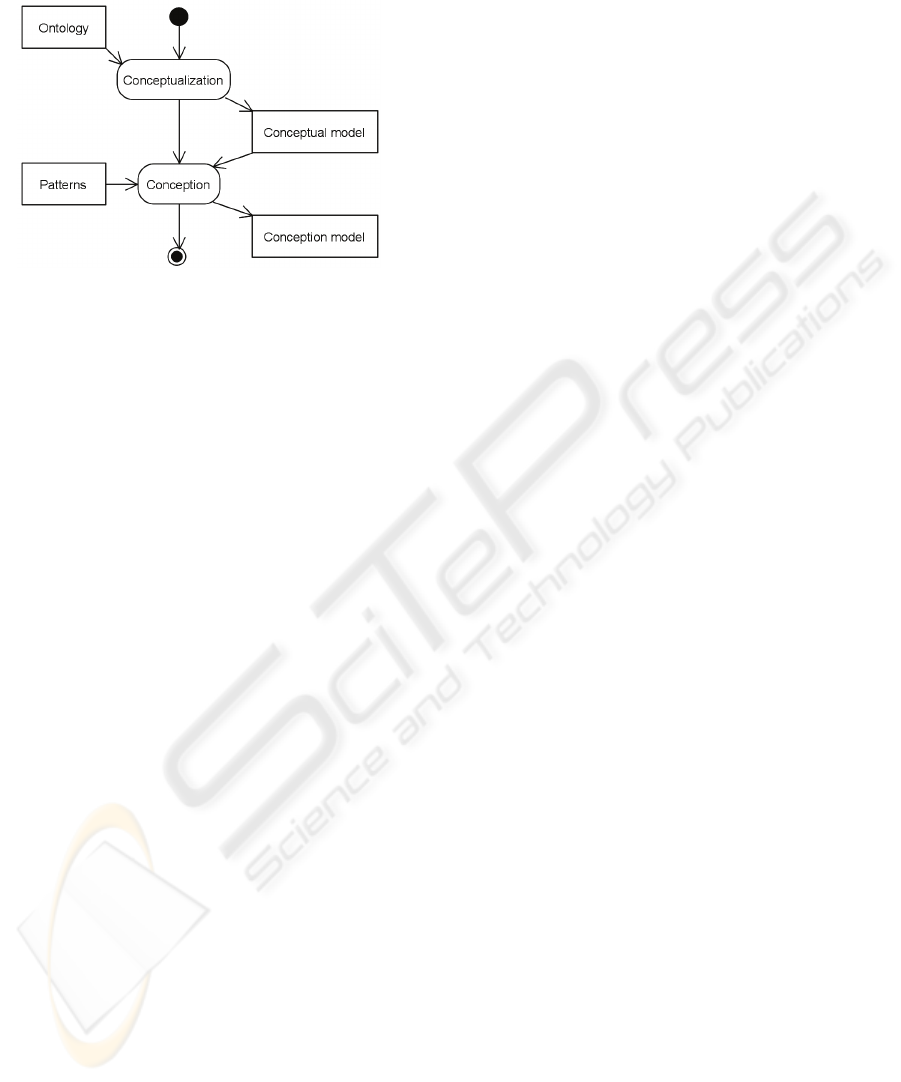
PEMBOP (see Figure 1) is composed of two
phases: conceptualization presented in section 3, and
conception presented in section 5. The
conceptualization phase is intended to identify the
process meta-model concepts; it is based on an
ontology described in section 2 and produces a
conceptual model. The conception phase is intended
to enrich the conceptual model. Each concept can be
represented as a set of meta-classes. These
transformations lean on meta-modelling techniques
described as design patterns and process meta-model
fragments described as business patterns, explained
in section 4. Section 6 presents the instantiation of a
29
Hug C., Front A. and Rieu D. (2008).
A PROCESS ENGINEERING METHOD BASED ON ONTOLOGY AND PATTERNS.
In Proceedings of the Third International Conference on Software and Data Technologies - ISDM/ABF, pages 29-36
DOI: 10.5220/0001874200290036
Copyright
c
SciTePress
process meta-model. Section 7 presents the related
works and section 8 concludes this paper.
Figure 1: The Process Engineering Method Based on
Ontology and Patterns.
2 THE PROCESS DOMAIN
ONTOLOGY
The proposed process domain ontology contains the
main concepts of existing process meta-models. In
this paper, an ontology is the representation of a set
of concepts within a domain and the relationships
between these concepts. The concerned domain here
is the information system engineering process. This
high-level ontology does not include secondary
concepts. The ontology is composed of two different
abstraction levels: the intentional abstraction level,
which represents the goals, the objectives of an
information system engineering process, and the
operational abstraction level, which represents the
actions to concretize these objectives. The ontology
comprises different viewpoints or modeling axis of a
process. A viewpoint is a process perspective; it is
not necessarily associated to a particular actor or
role as other viewpoint definitions (Sommerville et
al., 1995), (Finkelstein et al., 1990). Let us briefly
describe the different concepts of the process
domain ontology presented in Figure 2. We do not
aim to explain the different process meta-models
here, it has already been done in previous papers
(Rolland, 1998), (Hug et al., 2007).
Operational and intentional levels are
represented as stereotypes. We use different kinds of
graphical links to distinguish the different
associations between the concepts. A classic
association represents an association between two
concepts in the same abstraction level. For example,
Work Unit and Role are both at the operational
level; they are linked by a classic association. The
dashed lines with an arrow represent the
materialization of one concept of the intentional
level into another concept of the operational level.
For example, a Work Unit concretizes a Strategy.
The concept Work Unit represents something
that is done during the process. A Work Unit has
conditions, creates (out), uses (in) or modifies
(in/out) Work Products, and raises new Issues. This
concept comes from activity oriented process meta-
models such as SPEM (OMG, 2005), Open Process
Framework (OPF, 2005), OOSPICE (OOSPICE,
2002) and SMSDM (SA, 2004)which present the
activities and their scheduling for the conception of
a product (Rolland, 1998).
A Work Product is something produced or used,
during the process, that can be a deliverable (a
software for example). The Work Product concept
proceeds from product oriented process meta-
models, as the State Transition which is a ViewPoint
template presented in (Finkelstein, 1990), the
Statecharts meta-model (Harel, 1987), the Entity
meta-model (Humphrey et al.,1989), and the
Statemachine meta-model (OMG, 2007). Product
oriented process models couple the product state to
the activity which generates this state (Rolland,
1998).
A Role does something during the process. A
Role carries out a Work Unit, is responsible for a
Work Product and can select alternatives to issues.
This concept comes from activity oriented process
meta-models.
Issues are problems rising during the execution
of a process. When an Issue appears, some
alternatives respond to it. An Alternative is
supported or objected by one or more arguments. An
Argument can cite work product(s) to object or
support an alternative and to contribute to the
advance of a Work Unit. Issue, Alternative and
Argument concepts come from decision oriented
process meta-models such as CAD° (Conversation
among Agents on Decisions over Objects) of the
DAIDA project (Jarke et al., 1992), inspired from
Potts and Brun (Potts et al., 1988), and IBIS(Kunz et
al., 1970). Decision oriented process models present
the successive transformations of a product or
elicitations due to decisions (Rolland, 1998).
A Context is composed of a Situation and an
Intention. The Intention is a goal, an objective that
the application engineer has in mind at a given point
of time (Rolland et al., 1999).
ICSOFT 2008 - International Conference on Software and Data Technologies
30
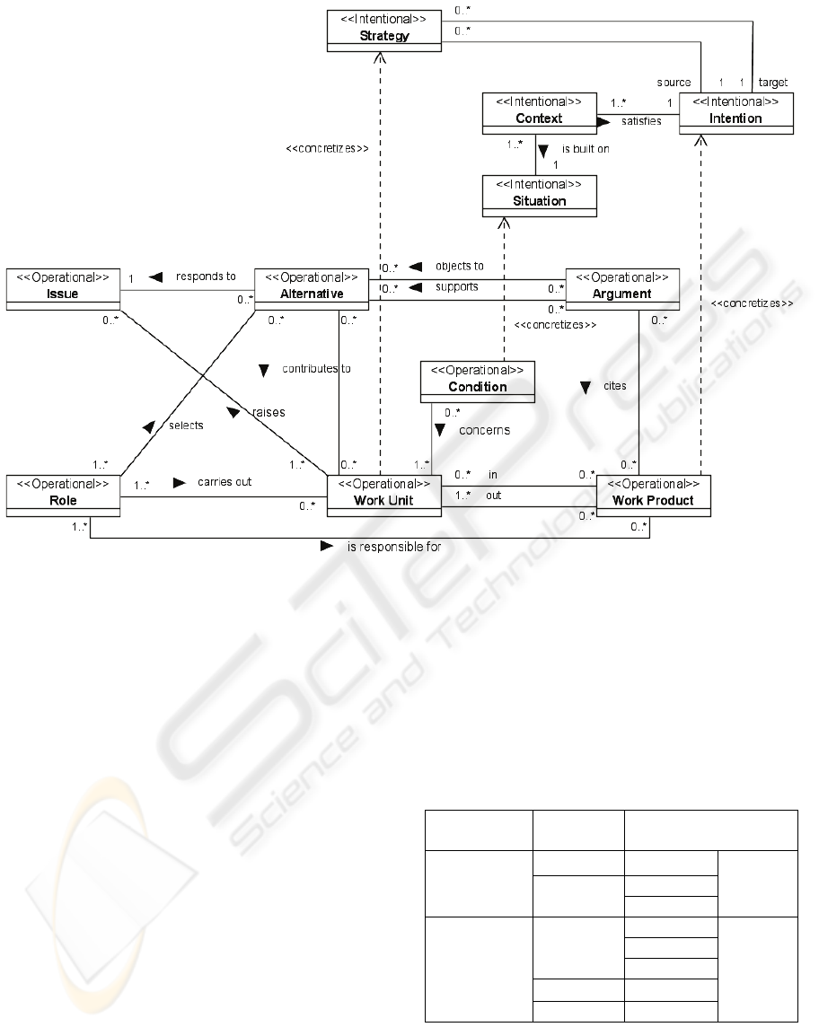
Figure 2: The process domain ontology.
The Situation represents the part of the product
undergoing the process (Plihon et al., 1995); it is
concretized by a Condition as well as an Intention is
concretized by a Work Product.
The notion of context was introduced in the
European project NATURE from which a meta-
model of the same name was defined (Rolland et al.,
1995). The context oriented process models consider
the situation and the intention of an actor (analyst,
method engineer…) at a given moment of the
project (Rolland, 1998).
At last, a Strategy is an approach, a manner to
achieve an Intention. It allows joining a source
intention to a target intention. A Strategy is
concretized by a Work Unit. The strategy concept
comes from the strategy oriented process models
that allow representing multi-approach processes
and plan different possible ways to elaborate the
product basing on intention and strategy notions
(Rolland, et al., 1999). As far as we know, MAP
(Rolland, et al., 1999) is the only strategy oriented
process meta-model to date. This meta-model allows
representing different strategies to achieve
intentions.
The ontology is composed of different abstraction
levels and viewpoints: Table 1 sums up for each
concept, which are its viewpoint and its abstraction
level. The concepts of Role, WorkProduct and Work
Unit are used in activity, product and decision
viewpoints. The concept of Intention is used by
Strategy and Context viewpoints.
Table 1: Abstraction levels, viewpoints and concepts.
Abstraction
level
Viewpoint Concept
Strategy Strategy
Context
Intentional
Context
Situation
Intention
Issue
Alternative
Decision
Argument
Product
Operational
Activity Condition
Role,
Work
Product,
Work unit
Some concepts of the ontology cannot be separated
from other concepts. Their existence depends on
other concepts existence. Table 2 presents the
depender concepts and their dependee concepts. For
A PROCESS ENGINEERING METHOD BASED ON ONTOLOGY AND PATTERNS
31
example, an alternative cannot exist without an
issue, but an issue can exist without an alternative.
Some concepts compulsorily depend on more than
one concept: a context cannot exist without a
situation and an intention. Other concepts depend on
at least one concept, for example: a role can depend
on a work unit, an alternative or a work product.
Table 2: The depender concepts and their dependee
concepts.
Depender Dependee
Strategy {Source Intention ∧ Target Intention}
Context {Situation ∧ Intention}
Argument Alternative
Alternative Issue
Condition Work Unit
Role {Alternative ∨ Work Unit ∨ Work
Product}
Though the ontology only contains the main
concepts of process engineering for information
system engineering, it is lead up to be enriched by
method engineering experts if new viewpoints are
found in new process meta-models. The next section
presents the conceptualization phase, which is based
on the process domain ontology.
3 THE CONCEPTUALIZATION
PHASE
During the conceptualization phase (see Figure 3),
the method engineers choose the needed concepts
from the ontology to produce a process meta-model
called conceptual model. There are different ways of
choosing the right concepts. Firstly, the method
engineers can choose the concepts according to their
abstraction level: intentional or operational. If the
method engineers want intentional (respectively
operational) process models to be developed, they
select intentional (respectively operational)
concepts. The method engineers can also choose the
concepts according to their viewpoint. The work unit
and work product concepts selection that represent
the activity and the product viewpoints, allows
creating activity oriented process models and
product oriented process models.
When choosing a concept, the dependee concepts
and the associations between them are “imported” in
the conceptual model. The dependee strategy
partially ensures the integrity of the conceptual
model each time the method engineers add a new
concept from the process domain ontology.
Nevertheless, our objective is not to check the
consistency and the integrity of the process meta-
model. This task is not in the scope of our research.
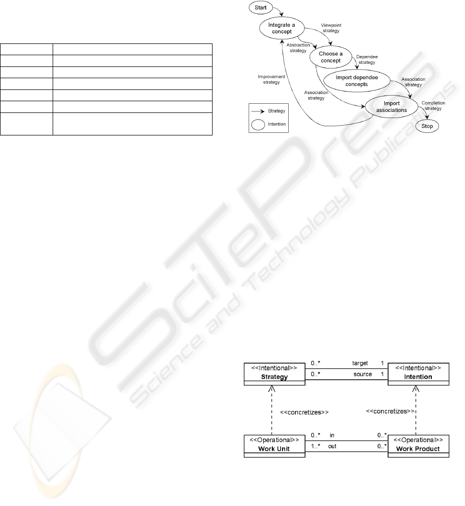
The conceptualization phase in Figure 3 is
represented in the MAP formalism (Rolland, et al.,
1999): the strategies are represented by edges
between intentions, represented by nodes.
Figure 3: The conceptualization phase represented as a
MAP.
To exemplify our proposition, let us present a
problem a method engineer can meet. He wants to
represent an information system engineering process
model showing two viewpoints: strategy and
activity. First, he has to build a process meta-model
including these two viewpoints. Figure 4 shows an
example of a conceptual model where the method
engineer chooses the following concepts: Strategy,
Intention to represent the strategy viewpoint of the
process, and, Work Unit and Work Product to
represent the activity viewpoint of the process. All
the associations between the selected concepts are
imported into the conceptual model. The constraint
of the depender-dependee is observed: the concept
Strategy has source intentions and target intentions.
Figure 4: Example of a conceptual model.
4 PATTERNS
The conception phase consists of completing the
conceptual model using meta-modeling techniques
(design patterns and process meta-model fragments)
ICSOFT 2008 - International Conference on Software and Data Technologies
32
to obtain a conception model. Design patterns
describe a frequently occurring problem in a context
and a general repeatable solution that resolves it.
Design patterns can be reused to enrich the
conception model. A lot of design patterns already
exist, but they still have to be adapted for process
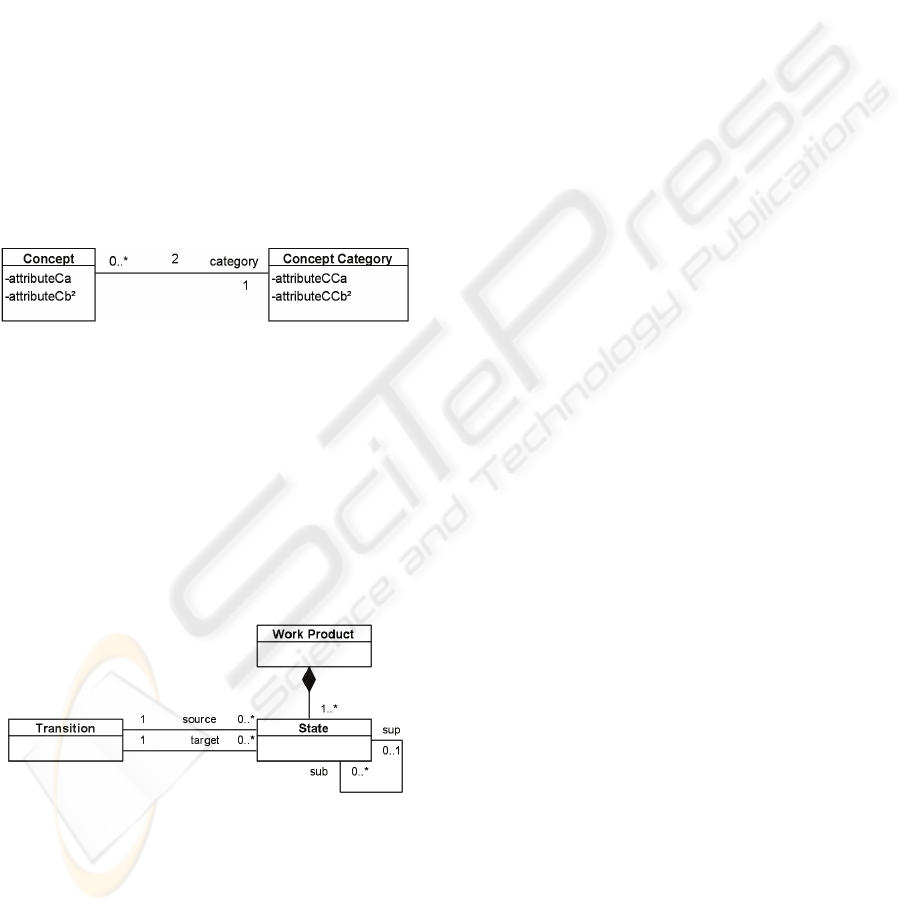
meta-modelling. Figure 5 shows the “Concept-
Concept-Category” design pattern (Hug et al., 2007).
This pattern allows the partition of concept
knowledge: specific knowledge on the one hand, and
common knowledge to many concepts on the other
hand, using the Item-Description Pattern (Coad,
1992). The pattern also allows instantiating the
properties of the concepts at different instantiation
levels, to define general properties at the model level
and specific properties at the process level, using the
Deep Instantiation (Atkinson et al., 2001). The
potencies “2” on the association and the attributes
comes from the Deep Instanciation. The “Concept-
Concept category” pattern is strongly useful for
process meta-modelling.
Figure 5: The “Concept-Concept Category” design
pattern.
Process meta-model fragments are part of
existing process meta-models that can be reused to
detail one or more concepts of the conceptual model
developing secondary concepts. Figure 6 shows a
process meta-model fragment which can be reused
in order to detail the concept of Work Product. New
classes are added in the conception model: State and
Transition. This fragment comes from the State-
Transition product oriented process meta-model.
Figure 6: Example of a process meta-model fragment
extracted from State-Transition.
Process meta-model fragments are represented as
business patterns to standardize their representation
with design patterns. The design patterns and the
business patterns are created by method engineers
when they need to. Experts in information system
engineering validate the new patterns to make them
available to other method engineers. Experts can
also create new patterns from technology watch in
information system engineering and method
domains. PEMBOP is presented as a pattern system
composed of process patterns (the method process it-
self) and product patterns (design and business
patterns) in order to standardize their representation.
All the patterns (process, design and business) are
represented in the formalism P-SIGMA (Conte et al.,
2002), a common formalism for patterns
representation that allows the clarification of the
patterns selection interface and facilitates the
organization of pattern systems.We also dispose of a
tool, AGAP (Conte et al., 2002), a development
environment for defining and using patterns. This
tool integrates a repository consisting of the design
patterns, the business patterns (fragments) and the
process patterns.
5 THE CONCEPTION PHASE
During the conception phase, the method engineers
select the concepts from the conceptual model they
want to enrich. A list of appropriate patterns is
proposed. Reports of experts and measures
constitute this list. The method engineers choose to
reuse a particular pattern according to different
strategies: by the resolved problem, by its frequency
of use or by its adequacy with the chosen concept.
Every pattern description details the problem it
resolves. The frequency of use indicates if the
pattern is often reused with the chosen concept. The
adequacy is a subjective measure filled in by the
method engineers who reuse the pattern for this
concept and indicate if it is relevant or not. If no
existing patterns satisfy the method engineers, they
can complete the list of appropriate patterns adding a
new pattern. Experts have to validate this new
pattern later, so that other engineers could reuse it.
The method engineers can add or delete
associations, aggregations, or compositions between
concepts. The method engineers can choose to
continue the improvement of the conception model
or to stop the process. The conception phase can also
be represented as a MAP, but we do not present it in
this paper because of lack of space.
In our example, the method engineer carries out
these actions on the conceptual model to obtain a
conception model specific to the organization needs
shown in Figure 7:
A PROCESS ENGINEERING METHOD BASED ON ONTOLOGY AND PATTERNS
33
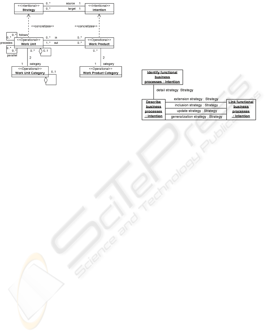
Figure 7: Example of a conception model.
1. Reuse the “Concept-Concept Category” pattern
for the Work Unit concept, because he needs to
distinguish a phase from an activity, and he needs
to define properties about an activity in general
and properties of the execution of an activity in a
particular project. For example, he needs to
define properties for the activity “Functional use
cases generation” in general and properties of the
execution of this activity in a particular project.
2. Reuse the “Concept-Concept Category” pattern
for the Work Product concept, because he uses
different kinds of work products: use case
diagrams, documents, etc. He also needs
properties defined at the model level and at the
execution level. For example, he needs to define
properties for a “Functional use cases model” in
general and for a functional use cases model in a
particular project.
3. Add a reflexive association called “Parallel” to
the Work Unit concept because two work units
can be executed in parallel. Add a reflexive
association called “precedes-follows” to the Work
Unit concept to represent a sequence of work
units. Add a reflexive aggregation to the Work
Unit concept to represent the fact that a work unit
belongs to an other work unit. Finally, add a
reflexive aggregation to the Work Unit Category
concept to represent the fact that a work unit
category can comprised work unit categories.
6 INSTANTIATION
Once the conception model (process meta-model) is
ready, the method engineer can instantiate it for
particular process models.
Figure 8 shows the instantiation of the conception
model of Figure 7 for the intentional abstraction
level of an information system engineering process
model. The example describes the situations met at
the beginning of a project, when the business
process analyst and the use cases analyst have to
define the business processes involved in the project.
The example details three intentions and the
strategies to achieve them. For example, when the
use cases analyst has described the business
processes, and if he wants to link the functional
business processes, he can use four strategies:
extension, inclusion, update, or generalization.
Figure 8: Extract of an intentional process model.
Figure 9 shows the instantiation of the conception
model of Figure 7 for the operational abstraction
level of an information system engineering process
model, inspired from Symphony (Hassine et al.,
2002). “Organizational specification requirements”
is a Work Unit of “Phase” Work Unit Category.
“Functional use cases generation” and “Functional
use cases description” are Work Units of “Activity”
Work Unit Category. The “Functional use cases
generation” activity produces a “Functional use
cases model” of “Use case diagram” Work Product
Category.
The work product “Complete functional use
cases model” in the operational part of the process
model (Figure 9) concretizes the intention “Link
functional business processes” in the intentional part
of the process model (Figure 8). Different scenarios
of the Activity “Functional use cases connection”
can concretize the various strategies to achieve the
intention “Link functional business processes”.
These process models can be then instantiated
for each information system project. This first
example shows that the PEMBOP is structuring and
allows building unified, fitted, and multi-viewpoints
process meta- models and models.
7 RELATED WORKS
In this section, we discuss some works related to
information system engineering process. (Fiorini et
al., 2001) present a process reuse architecture. This
architecture allows storing, classifying, and
retrieving process frameworks, process patterns, or
usual processes. Our solution is different because we
ICSOFT 2008 - International Conference on Software and Data Technologies
34
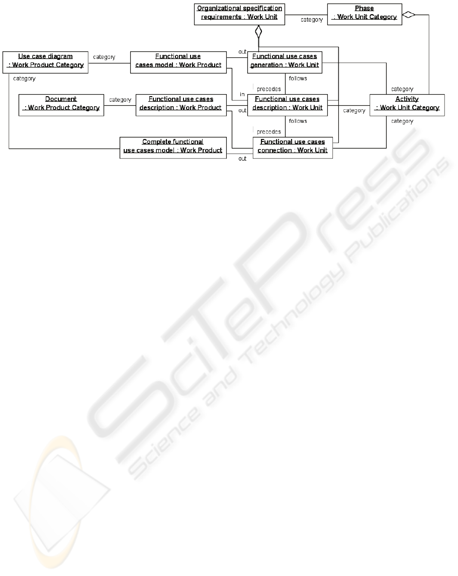
Figure 9: Extract of an operational process model.
provide a method to build process meta-models,
whereas the process reuse architecture allows
building process models.
(Tran et al., 2007) provide a meta-model to
define process patterns to build and improve process
models. This solution focuses on process models
while our solution focuses on process meta-models.
However, some mechanisms could be adapted to
process meta-modelling (pattern searching,
selecting, etc.).
(Leppanen, 2006) presents an ontology for
information system development (ISD). This
ontology aims to help understanding ISD, analyzing
and comparing ISD artefacts and supporting the
creation of new ISD artefacts. It is a low-level
ontology and the author does not provide a method
to help building information systems using the
ontology. This ontology comprises different
domains: action (activity oriented), actor, object
(product oriented), and purpose (decision and goal
oriented). It does not include intentional level as
strategy and context.
At last, (Henderson-Sellers et al., 2005) present a
process meta-model for software development
methodologies and their enactment. This process
meta-model comprises producers, work products,
work units and stages. There are no decision,
strategy, and intention viewpoints.
8 CONCLUSIONS
This article presents a process domain ontology
whose main concepts come from different types of
existing process meta-models. This ontology is the
base of the Process Engineering Method Based on
Ontology and Patterns that helps building unified,
fitted and multi-viewpoints process meta-models for
information system engineering. PEMBOP is
composed of two phases: the first phase,
conceptualization, allows the method engineer
choosing the different needed concepts from the
ontology to build a first version of the process meta-
model called the conceptual model. The second
phase, conception, allows enriching this model
mainly using patterns. This phase produces a new
version of the process meta-model called conception
model. Then, the method engineer can instantiate the
process meta-model according to the needs of the
organization or the project.
In the future, we have to validate the method,
rebuilding existing process meta-models and models
using case studies. Once we validate the method, we
will then have to implement a tool that will easily
guide the users in the construction of their process
meta-models: a workflow could assist the two
phases, conceptualization, and conception.
REFERENCES
Atkinson, C., & Kühne, T. (2001). The Essence of
Multilevel Metamodeling. In UML 2001, LNCS,
2185, 19-33, Springer-Verlag, London
Coad, P. (1992). Object-Oriented Patterns.
Communication of the ACM, 35 (9), 152-159.
Conte, A., Fredj, M., Hassine, I., Giraudin, J.-P., & Rieu,
D. (2002). A tool and a formalism to design and apply
patterns. In OOIS '02: Proceedings of the eight
International Conference on Object-Oriented.
Information Systems, (pp. 135-146). London, UK:
Springer-Verlag.
Finkelstein, A., Kramer, J., & Goedicke, M. (1990).
Viewpoint oriented software development. In
Proceedings of the third International Workshop on
Software Engineering and Its Applications, (pp. 337-
351).
A PROCESS ENGINEERING METHOD BASED ON ONTOLOGY AND PATTERNS
35

Fiorini, S. T., do Prado Leite, J. C. S., & de Lucena, C. J.
P. (2001). Process reuse architecture. In K. R. Dittrich,
A. Geppert, & M. C. Norrie (Eds.) CAiSE 2001:
Advanced Information Systems Engineering, 13th
International Conference, vol. 2068 of Lecture Notes
in Computer Science, (pp. 284-298). Springer.
Harel, D. (1987). Statecharts: A visual formulation for
complex systems. Sci. Comput. Program., 8 (3), 231-
274.
Hassine, I., Rieu; D., Bounaas, F., & Seghrouchni, O.
(2002). Symphony: a conceptual model based on
business components. In IEEE International
Conference on Systems, Man and Cybernetics, 3, 34-
39.
Henderson-Sellers, B., & Gonzalez-Perez, C. (2005). A
comparison of four process metamodels and the
creation of a new generic standard. Information &
Software Technology, 47 (1), 49-65.
Hug, C., Front, A., & Rieu, D. (2007). Ingénierie des
processus: une approche à base de patrons. In Actes du
XXVème Congrès INFORSID, Perros-Guirec, France,
22 au 25 mai 2007 , (pp. 471-486).
Humphrey, W. S., & Kellner, M. I. (1989). Software
process modeling: principles of entity process models.
In ICSE '89: Proceedings of the 11th international
conference on Software engineering, (pp. 331-342).
New York, NY, USA: ACM Press.
Jarke, M., Mylopoulos, J., Schmidt, J. W., & Vassiliou, Y.
(1992). Daida: an environment for evolving
information systems. ACM Trans. Inf. Syst., 10 (1), 1-
50.
Kruchten, P. (2000) The Rational Unified Process: An
Introduction, Addison-Wesley.
Kunz, W., & Rittel, H. W. J. (1970). Issues as elements of
information systems. Working Paper 131, Heidelberg-
Berkeley.
Leppanen, M. (2006). Towards an ontology for
information systems development. In J. Krogstie, T.
Halpin, & H. Proper (Eds.) EMMSAD'06: Proceedings
of the Workshop on Exploring Modeling Methods for
Systems Analysis and Design, (pp. 363-374).
Luxembourg, Luxembourg, EU: Namur University
Press, Namur, Belgium, EU.
OMG (2005). Software Process Engineering Metamodel,
version 1.1. Tech. Rep. formal/05-01-06, Object
Management Group.
OMG (2007). Unified Modeling Language:
Superstructure, version 2.1.1. Tech. Rep. formal/2007-
02-03, Object Management Group.
OOSPICE. (2002). Software Process Improvement and
Capability Determination for Object-Oriented/
Component-Based Software Development. Retrieved
October, 7, 2002 from www.oospice.com
Open Process Framework. (2005). Retrieved December,
16, 2005 from http://www.opfro.org
Plihon, V., & Rolland, C. (1995). Modelling ways-of-
working. In CAiSe '95: Proceedings of the seventh
International Conference on Advanced Information
Systems Engineering, (pp. 126-139). London, UK:
Springer-Verlag.
Potts, C., & Bruns, G. (1988). Recording the reasons for
design decisions. In ICSE '88: Proceedings of the 10th
international conference on Software engineering, (pp.
418-427). Los Alamitos, CA, USA: IEEE Computer
Society Press.
Rolland C., Souveyet C., Moreno M. (1995). An Approach
for defining ways-of-working. Information System
Journal, 20 (4), 337-359.
Rolland, C. (1998). A comprehensive view of process
engineering. In CAiSE '98: Proceedings of the 10th
International Conference on Advanced Information
Systems Engineering, (pp. 1-24). Pisa, Italia: Springer-
Verlag.
Rolland, C., Prakash, N., & Benjamen, A. (1999). A multi-
model view of process modelling. Requirements
Engineering, 4 (4), 169-187.
Sommerville, I., Kotonya, G., Viller, S., & Sawyer, P.
(1995). Process viewpoints. In EWSPT '95:
Proceedings of the Fourth European Workshop on
Software Process Technology, (pp. 2-8). London, UK:
Springer-Verlag.
Standards Australia. (2004). Standard Metamodel for
Software Development Methodologies, AS 4651—
2004.
Tran, H. N., Coulette, B., & Dong, B. T. (2007). Modeling
process patterns and their application. In ICSEA '07:
Proceedings of the International Conference on
Software Engineering Advances, (p. 15). Washington,
USA: IEEE Computer Society.
ICSOFT 2008 - International Conference on Software and Data Technologies
36
