
AUTOMATIC GENERATION OF INTERACTIVE PROTOTYPES
FOR DOMAIN MODEL VALIDATION
António Miguel Rosado da Cruz
E.S.T.G., Instituto Politécnico de Viana do Castelo, Av. do Atlântico, s/n 4900-348 Viana do Castelo, Portugal
João Pascoal Faria
Faculdade de Engenharia da Universidade do Porto/INESC Porto, Rua Dr. Roberto Frias, s/n 4200-465 Porto, Portugal
Keywords: Model-driven development, domain model validation, form-based applications, interactive prototype,
automatic generation.
Abstract: This paper presents an approach to domain models validation with customers, end users and other
stakeholders. From an early system model that represents the main domain (or business) entities in a UML
class diagram, with classes, relationships, attributes and constraints, it is automatically generated an
interactive form-based application prototype supporting the basic CRUD operations (create, retrieve, update
and delete). The generated form-based user interface provides some features that are derived from the
model’s constraints and increase the prototype usability. This prototype allows the early validation of core
system models, and can also be used as a basis for subsequent developments. The prototype generation
process follows a model-driven development approach: the domain model, conforming to a defined domain
meta-model, is first transformed to an application model, conforming to a defined application meta-model,
based on a set of transformation rules; then a generator for a specific platform produces the executable files
(currently, XUL and RDF files).
1 INTRODUCTION
Software models help engineers deal with the
complexity of software systems when analyzing the
problem domain or designing a software solution.
Software models capture relevant parts of the
problem and solution domains and are typically used
as a means for reasoning about the system properties
and communicating with the stakeholders.
A good software engineering practice is to build
an early system model, which captures the
requirements for the system being built. One way of
building such a model is to develop a domain model
and use case model, supplemented by a non-
functional user interface prototype (Jacobson et al.,
1999). In this paper, we focus on the domain model.
A domain model captures the static structural
properties of the system, namely the main
domain/business entities, attributes, and relations
through UML class diagrams. Domain constraints
may also be captured in natural language or in OCL
(Object Constraint Language), and attached to the
class diagram. Operations are usually not considered
in early domain models.
In this paper, we present an approach
(comprising transformation rules, source and target
metamodels and a set of tools) to automatically
generate an interactive prototype from a domain
model, for domain model validation purposes with
customers, end users and other stakeholders.
In our approach, it is considered a UML domain
model that includes the domain/business entities
(represented as classes), its attributes, relations and
the intra-object constraints. These class constraints
may be written in OCL (Object Constraint
Language), and can be attached to the class diagram.
The system’s dynamics is, in this approach,
limited to CRUD operations (Create, Retrieve,
Update, and Delete).
The generated interactive system prototype has
quite a few applications. It may be used to elicit and
validate requirements with end users and customers
or to validate the domain model and
domain/business constraints by the modeler.
206
Miguel Rosado da Cruz A. and Pascoal Faria J. (2008).
AUTOMATIC GENERATION OF INTERACTIVE PROTOTYPES FOR DOMAIN MODEL VALIDATION.
In Proceedings of the Third International Conference on Software and Data Technologies - SE/GSDCA/MUSE, pages 206-213
DOI: 10.5220/0001887402060213
Copyright
c
SciTePress
The main contribution of this work is an
approach, and a tool, for generating an executable
interactive system prototype, that can be used for
domain/business model validation and requirements
elicitation and validation. The kinds of systems
targeted by this approach are business software
applications with form based user interfaces.
In the next section, it is presented an overview of
domain/business model validation techniques.
Section 3 presents the general architecture of our
approach and tool, and section 4 explains the
transformation rules from the domain to the
application meta-models, defined for generating the
prototype and the default user interface (UI). Section
5 presents a short review of related work in the
fields of interactive prototypes automatic generation.
Finally, section 6 draws some conclusions and
presents some directions for future work.
2 DOMAIN MODEL VALIDATION
Modern software development processes typically
use an iterative and incremental approach for
developing software (Pressman, 2005). This allows
the software engineers to cope with the ambiguities
of the human language used for requirements
elicitation.
Traditionally, a requirements document is
developed to describe the features desired to the
system (Pressman, 2005). Increasingly often, the
functional and informational requirements are also
captured in semi-formal visual models (Kleppe et
al., 2003) or in formal models with a mathematical
foundation (Fitzgerald et al., 2005; Meyer, 2006;
Schoeller et al., 2006).
Since most of the defects found in software
products have their origin in the requirements and
design phases (Frost and Campo, 2007) and the cost
of correcting defects increases dramatically with the
time elapsed since their introduction, it is important
to assure the quality of the requirements models.
A model’s quality can be checked in two
complimentary ways (Fitzgerald et al., 2005): by
checking its internal consistency, and by assessing
its external consistency. Internal consistency relates
to verifying that the model doesn’t contradict itself,
meaning that the model “describes something”. One
way of assessing internal consistency is through
syntax and type checking. External consistency
validates that the model “describes the correct
thing”, that is, it maps the user requirements. This is
more difficult to assess, because one can never be
sure if the model correctly captures the user’s
requirements. One way of doing this external
validation is by executing the model and analyzing
its behavior with the end-users and other
stakeholders (Fitzgerald et al., 2005), through an
appropriate user interface. The goal of our approach
is to generate automatically a default user interface
(and underlying functionality) from the model itself,
in the case where the model is an early structural
domain model.
3 GENERAL APPROACH
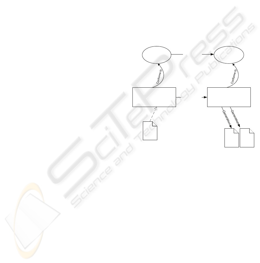
Figure 1 presents an architectural overview of our
approach for generating an interactive system
prototype from a domain model.
DomainMM AppMM
Domain Model
Application Prototype
Model
Mapping rules
Model
Transformation
XMI
XUL
files
RDF file
Figure 1: Model-driven approach to application prototype
generation.
The domain model represents the main domain
(or business) entities in a UML class diagram, with
classes, relationships, attributes and constraints. It is
represented as an instance of a defined metamodel
(DomainMM in figure 1), which is compatible with
EMOF and EMF’s Ecore (Eclipse, 2005; Merks and
Steinberg, 2005). Eventually, importers from other
formats, such as XMI, will be developed.
The generator works in two steps. In the first
step, the input domain model (an instance of
DomainMM) is transformed into a form-based
application model, conforming to a defined
metamodel (AppMM in figure 1). A form is created
for each non-abstract class with self or inherited
attributes, and then populated with widgets of
several types (labels, text fields, listboxes, buttons),
according to the class attributes and relationships.
Section 4 explains the rules used in this process.
AUTOMATIC GENERATION OF INTERACTIVE PROTOTYPES FOR DOMAIN MODEL VALIDATION
207
In the second step, an executable application
prototype is generated from the application model.
The code generated is a set of XUL (XML User
Interface Language) files with embedded javascript
functions, for the windows and functionality
definition, and a RDF (Resource Description
Framework) file, for storing the data objects. The
generated prototype provides basic CRUD
operations over domain model instances.
The model transformer and the code generator
are written in C#. The prototype generated must be
run using Xulrunner. See (MDC, 2008) for more
information about XUL, RDF and Xulrunner.
The structure of both the domain and application
metamodels is presented in the appendix. Their
detailed description is outside the scope of this
paper, for space limitation rules. The DomainMM
metamodel defines a modeling language that is a
subset of UML for describing domain models. It
describes classes, its attributes and methods,
relationships between classes and class level
constraints consisting of OCL expressions. The
AppMM metamodel defines a modeling language
for interactive applications. Its main modeling
elements are windows, being SelectionDialog and
viewDetailsDialog special types of windows.
Windows aggregate buttons and/or containers,
which may be Forms or AggregationLists.
The next section describes the transformation
rules used to generate a user interface from a domain
model.
4 TRANSFORMATION RULES
This section presents the rules defined to transform
different elements of the domain model into
appropriate user interface elements and their
underlying functionality. To illustrate the
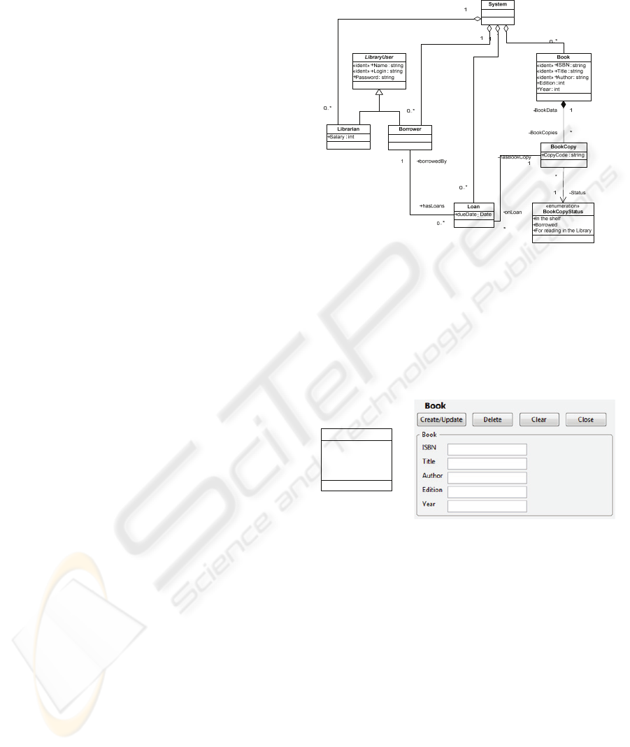
transformation rules, it will be used a Library
System example with the domain classes diagram
presented in figure 2.
4.1 The Root Class System
In order to be able to identify the application UI
entry points, the domain model must be rooted in a
special class named System. This is a special class,
with no attributes, that aggregates the entity classes
that shall be directly accessed by the user. Each
aggregation from System produces a window with a
list of instances of the corresponding class, and
buttons to edit a selected instance (view, update or
remove), or add a new instance. These buttons give
access to a form for editing or adding an instance of
the class, as described next.
Figure 2: The example LibrarySystem domain model.
4.2 Transforming Single Classes
For each non-abstract class with self or inherited
attributes, it is generated a form window with a label
and an input field for each attribute, and a set of
buttons explained next (see figure 3).
«ident» +ISBN : string
«ident» +Title : string
«ident» +Author : string
+Edition : int
+Year : int
Book
Figure 3: Class Book and the form that is generated.
The Create/Update button is used to submit the
data entered for a new instance or the changes
introduced for an existing instance. After performing
this operation, the window remains open and
editable. When a new or changed instance is
submitted, it is checked that the values entered obey
their declared data types, the identifying attributes
(marked with the «ident» stereotype) are filled in,
and the intra-objects constraints (see section 4.6) are
satisfied
The Delete button deletes the current instance. It
is not available for new instances. Deletion is
performed in cascade, i.e., all the referencing objects
are recursively deleted as well. The Clear and Close
button have obvious functions.
ICSOFT 2008 - International Conference on Software and Data Technologies
208
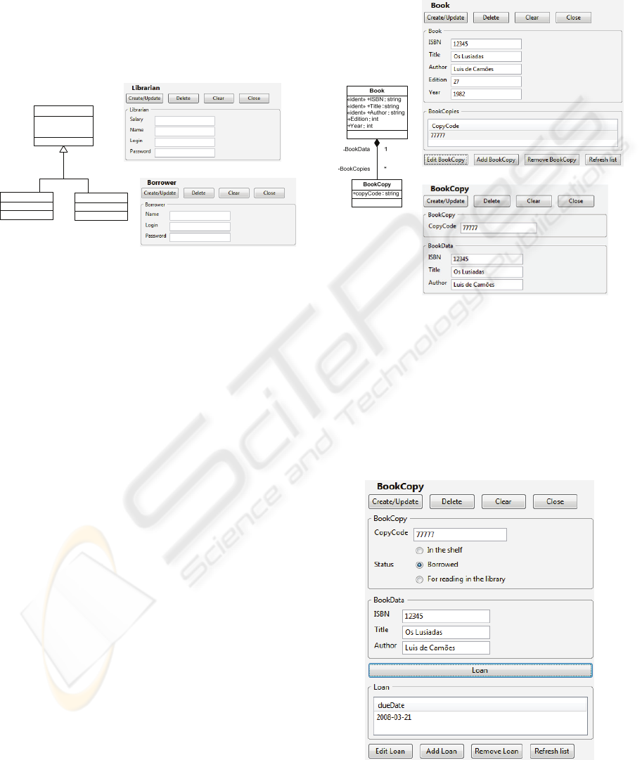
4.3 Transforming Inheritance
Hierarchies
In the current version, only single inheritance is
supported, and forms are generated only for the leaf
classes of the inheritance hierarchy. Each leaf class
inherits all the attributes and constraints from its
ancestor classes, and then has the same treatment as
single classes (see figure 4).
«ident» +Name : string
«ident» +Login : string
+Password : string
LibraryUser
+Salary : int
Librarian
Borrower
Figure 4: Forms generated for the classes that inherit from
the abstract class LibraryUser.
4.4 Transforming Associations,
Aggregations and Compositions
For each relationship (composition, aggregation or
association) between two classes, information about
related objects and/or links to related objects are
generated in each of the corresponding windows.
The elements generated depend on the kind of
relationship, its multiplicity, and the navigation path
followed. The information that is shown about
related objects is the value of the identifying
attributes (marked with the «ident» stereotype). If no
attribute is marked, all the attributes are considered
identifying attributes. Role names are used to group
the identifying attributes in the form generated. If a
role name is not provided, it is used the class name.
In the case of a to-many relationship, it is shown
a list of related instances, with the identifying
attributes of each instance, and a set of buttons for
editing (viewing or updating) or removing the
instance currently selected, or adding a new
instance. For example, the Book window in figure 5
presents a list of related BookCopy instances,
identified by the CopyCode attribute. The "Edit
BookCopy" and "Add BookCopy" buttons give
access to the BookCopy window (to edit or create a
related BookCopy instance)
In the case of a to-many composition, the list of
related instances is always shown. In the case of a
to-many aggregation or association, as is the case
of the association between BookCopy and Loan in
figure 6, the list of related instances is only shown
when requested by the user by pressing an
expand/collapse button.
Figure 5: Composition relationship between classes Book
and BookCopy, and the forms that are generated.
In the case of a to-one relationship (irrespective
of the relationship type), the identifying attributes of
the related instance are shown inside a group box
with the role name of the related instance. E.g., the
BookCopy window in figure 5 presents the
identifying attributes of the related Book instance
(named BookData).
Figure 6: Window BookCopy, illustrating the expandable
list of loans that derive from the one-to-many association.
AUTOMATIC GENERATION OF INTERACTIVE PROTOTYPES FOR DOMAIN MODEL VALIDATION
209
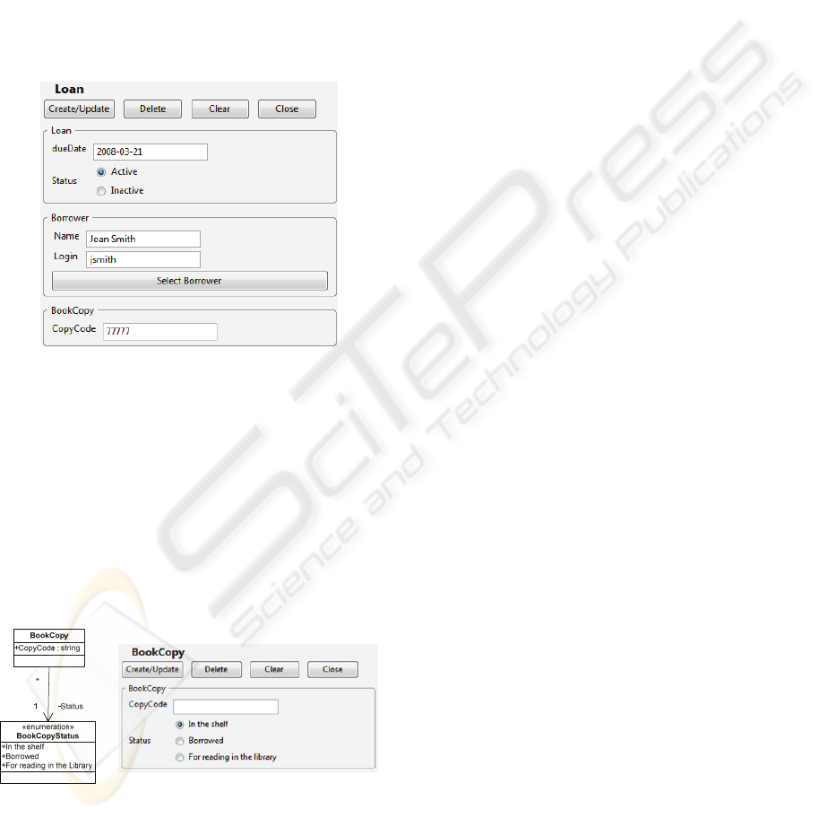
When the related to-one object is not in the
navigation path followed so forth, the user can
change the related instance through a Select button.
This button gives access to a pop-up window with a
list of instances (identified by their identifying
attributes), from which one can be selected. For
example, figure 7 shows the window that appears
when navigating from BookCopy to Loan. In this
case, a bookcopy instance would have to be
previously selected, and thus the “Select
BookCopy” button doesn’t appear in the Loan
window. By contrast, the "Select Borrower" is
shown.
Figure 7: Window Loan, which is shown when navigating
from a BookCopy instance to an instance of class Loan.
4.5 Handling Enumerated Types
Enumerated types are defined in the model as
classes with an «enumeration» stereotype. Normal
classes can have attributes of enumerated types or
to-one associations to enumerated types (in which
case the role name is used as an attribute name). A
radio group is generated for such attributes and
associations (see figure 8).
Figure 8: Relation between class Book and the enumerated
type BookCopyStatus. A list of radio buttons with the
enumeration fields is generated in the Book form.
4.6 Handling Constraints
Two kinds of business or domain constraints may be
specified in the domain model: structural constraints,
and non-structural constraints. Examples of the
former are the multiplicity of associations, and of the
latter, are OCL constraints. Each kind of constraints
may be further sub-divided into intra-object
constraints, applied to attributes within the same
object, and inter-object constraints, which may apply
to attributes of different objects and/or classes.
The prototype generator currently handles intra-
object constraints, by generating data entry
validation functions that are called every time a
“Create/Update” button is pressed in the appropriate
form.
Intra-object constraints may be specified, in the
domain model, using an OCL-like abstract language,
according to the meta-model shown in the appendix
(namely the class OclExpression). Constraint
expressions may have relational and logical
operators, attribute references, constants, etc.
An example of an intra-object constraint, in the
context of LibraryUser, is that a user’s password
must be different from its login name. In the
DomainMM metamodel’s abstract syntax this would
be defined as:
new UMLClassConstraint("CONSTRAINT 3",
new RelationalOpExp(
new StateExp("Login"),
RelationalOp.NEQ,
new StateExp("Password")))
5 RELATED WORK
Typical methodologies for modeling interactive
applications use disparate views, or (sub)models, to
capture different aspects of the domain (task model,
dialogue model, abstract and concrete presentation
models or application model) (Pinheiro da Silva,
2000).
Most of existing approaches to UI generation
require the specification of a UI model, like the ones
studied by Pinheiro da Silva (Pinheiro da Silva,
2000).
Some research has been made in order to model
interactive systems using UML diagrams (Pinheiro
da Silva, 2002), but they also involve the full
specification of the user interface.
As mentioned earlier, a typical approach to
software engineering using UML starts by
developing a sketch of the core system model by
producing a structural or domain model, which
ICSOFT 2008 - International Conference on Software and Data Technologies
210

models the system’s domain classes, its attributes,
relations and operations, and a functional or use case
model, which models the user’s intended operations
to be accomplished on the system through its user
interface. To test this core system model with the
users and other stakeholders it is needed a user
interface. There is some research on deriving user
interfaces from a model of the system core. In
(Martinez et al., 2002), Martínez et al. present a
methodology for deriving UIs from early
requirements existing in an organization’s business
process model. Their approach follows a set of
heuristics for extracting use cases and actors from
the business process model. Each use case’s normal
and exceptional scenarios are then specified using
message sequence charts enriched with UI related
information. These UI enriched sequence diagrams
are then used for automatically generating
application forms and state transition diagrams for
the interface objects and control objects present in
the sequence diagrams.
Elkoutbi et al. (Elkoutbi et al., 2006) also
approach UI generation by identifying usage
scenarios. Their approach starts from a system
domain structural model with OCL constraints and a
use case model, but proceed by formalizing each use
case through a set of UML collaboration diagrams,
each corresponding to a use case scenario. Then,
each collaboration diagram message is manually
labeled with UI constraints (inputData and
outputData) that identify the input and output
message parameters for the UI. From the UI
constraints it then automatically produces message
constraints with UI widget information. Statechart
diagrams are then derived from the UI labeled
collaboration diagrams on a per use case basis. A
statechart is created for each distinct class in a
collaboration diagram. Then, state labeling and
statechart integration are done incrementally, in
order to obtain only one statechart per collaboration
diagram, that is, per usage scenario. Elkoutbi’s
approach is then able to derive UI prototypes for
every interface object defined in the class diagram.
In (Nunes, 2001), Nunes uses activity diagrams
to represent all scenarios of a given use case in only
one model.
Other approaches to rapid prototyping, that allow
an early validation of the system model, involve the
construction of executable models using an action
language that allows to fully define the model’s
behavior. See, for instance (Luz and Silva, 2004).
The rapid adaptability of the system to the
changing requirements is approached, by (Yoder and
Johnson, 2002), through the separation of the
domain model, and the business rules and
constraints from the code, in a metadata layer. This
way, the system’s behavior changes only by
changing the object model (the metadata layer),
which is interpreted in runtime by an appropriate
running environment.
6 CONCLUSIONS AND FUTURE
WORK
An approach for interactive prototype generation has
been addressed in the paper, and a tool has been
developed for automatically applying that approach.
A software engineer effort, needed for generating an
interactive prototype, with the presented tool, is the
same effort that is necessary for producing an early
system domain model. So, minimal effort is put into
producing the system domain model and the
interactive prototype.
One purpose of the generated prototype may be
to validate the early system model, by creating and
maintaining instances of the domain classes. This is
not new, as the Eclipse Modeling Framework also
accomplishes this purpose. What is new is the
possibility of being the final user, or other
stakeholder, to use the prototype, because it is form-
based and close to what he/she expects to see in the
final software product.
The current prototype generator only produces
CRUD operations for each class, relying on
primitive object manipulation operations. The next
step will be to support also user defined methods
and generate the appropriate mechanisms in the user
interface to call those methods. In an initial stage of
domain modeling, these methods typically represent
important business transactions (or services or use
cases), such as, lend a book copy and return a book
copy. The form generated for a given class will
have a call button for each method defined. This
button will give access to a form with the structure
of the input method parameters (if any exist), and a
confirmation button that executes the method and
gives access to a second form with the structure of
the output method parameters (if any exist). Non
persistent classes may be added to the domain model
to define the input and output parameters. To be
able to execute a method, its behavior will have to
be specified in some implicit (through the constraint
language) or explicit form (through an action
language).
Other future developments include handling
inter-object constraints (multiplicity constraints,
AUTOMATIC GENERATION OF INTERACTIVE PROTOTYPES FOR DOMAIN MODEL VALIDATION
211

key constraints, and other more generic constraints),
and business rules with side effects (the triggering
of actions when certain conditions are met or certain
events occur, possibly modeled as aspects). The
calculation of derived attributes and the
presentation of default values in user forms shall
also be considered.
Another future development will include a use
case driven specification of the functional structure,
closely related to the domain model, in which “leaf”
use cases would be related to primitive CRUD
operations or user defined methods in the domain
classes or the root System class. This will enable the
generation of a user interface adapted for each user
profile (actor).
REFERENCES
Elkoutbi, M., I. Khriss, and R. Keller, 2006. Automated
Prototyping of User Interfaces Based on UML
Scenarios. In Journal of Automated Software
Engineering, 13(1), Springer Science+Business Media
B.V., January, pp. 5-40.
Eclipse, 2005. The Eclipse Modeling Framework (EMF)
Overview. In Eclipse Documentation. Available at:
http://help.eclipse.org.
Fitzgeralg, J., P. Larsen, P. Mukherjee, N. Plat and M.
Verhoef, 2005. Validated designs for object-oriented
systems, Springer-Verlag London.
Frost, A. and M. Campo, 2007. Advancing Defect
Containment to Quantitative Defect Management. In
Crosstalk - The Journal of Defense Software
Engineering, Dec 2007 Issue.
Jacobson, I., G. Booch, and J. Rumbaugh, 1999. The
Unified Software development Process, Addison-
Wesley.
Kleppe, A., J. Warmer, and B. Wim, 2003. MDA
Explained: The Model Driven Architecture – Practice
and Promise, Addison-Wesley Professional.
Luz, M. P. and A. Silva, 2004. Executing UML Models.
3
rd
Workshop in Software Model Engineering (WiSME
2004).
Martinez, A., H. Estrada, J. Sánchez, and O. Pastor, 2002.
From Early Requirements to User Interface
Prototyping: A methodological approach. In
Proceedings of the 17
th
IEEE International
Conference on Automated Software Engineering (ASE
2002), pp. 257-260.
MDC, 2008. Mozilla Development Center (beta).
http://developer.mozilla.org/en/docs/Main_Page (Last
accessed in March 3, 2008).
Merks, Ed and D. Steinberg, 2005. From Models to Code
with the Eclipse Modeling Framework. Presentation
made at Eclipse Con.2005. Available at
http://www.eclipsecon.org/2005/presentations/Eclipse
Con2005_Tutorial11final.pdf (Last accessed in March
3, 2008).
Meyer, B., 2006. Dependable Software. In Dependable
Systems: Software, Computing, Networks, Springer
Berlin / Heidelberg, Lecture Notes in Computer
Science vol. 4028, pp. 1-33.
Nunes, N. Jardim, 2001. Object Modeling for User-
Centered Development and User Interface Design:
The Wisdom Approach. PhD thesis, University of
Madeira.
Pinheiro da Silva, P., 2000. User interface declarative
models and development environments: A survey. In
Interactive Systems - Design, Specification, and
Verification: 7th International Workshop, DSV-IS
2000, Limerick, Ireland, June 2000. Revised Papers,
Springer Berlin / Heidelberg, Lecture Notes in
Computer Science vol. 1946, pp. 207–226.
Pinheiro da Silva, P., 2002 . Object Modeling of
Interactive Systems: The UMLi Approach. PhD thesis,
Faculty of Science and Engineering, University of
Manchester.
Pressman, R. S., 2005. Software Engineering – A
practitioner’s approach, 6
th
edition. Mc Graw Hill.
Schoeller, B., T. Widmer, and B. Meyer, 2006. Making
specifications complete through models. In
Architecting Systems with Trustworthy Components,
Springer Berlin / Heidelberg, Lecture Notes in
Computer Science vol. 3938, pp. 48-70.
Yoder, J. and R. Johnson, 2002. The Adaptive Object-
Model Architectural Style. In Software Architecture:
System Design, Development and Maintenance. 3
rd
IEEE/IFIP Conference on Software Architecture,
August 25-30, Montréal, Québec, Canada, pp. 3-27.
ICSOFT 2008 - International Conference on Software and Data Technologies
212
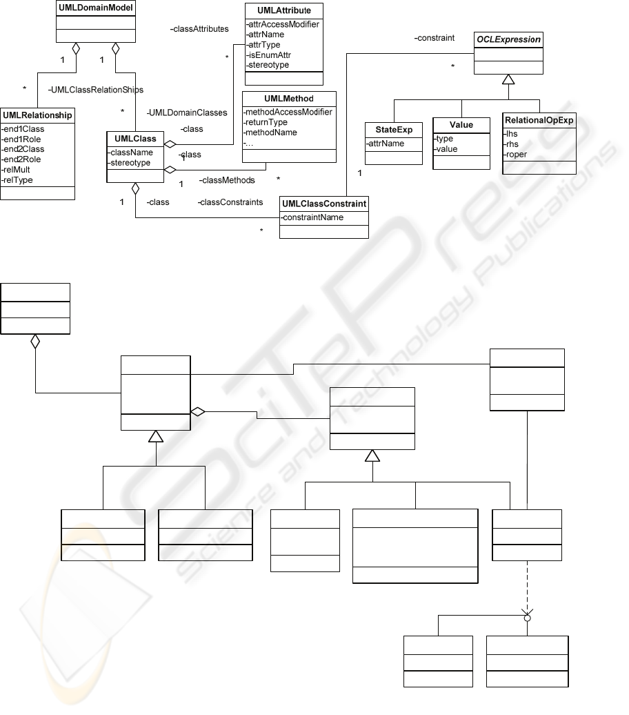
APPENDIX – Partial View of the Domain and Application Meta-Models
DomainMM metamodel:
-model
-model
-classConstraint
AppMM metamodel:
-name
Application
-name
-type
-visible
Window
-containerName
-typeOfContainer
Container
SelectionDialog viewDetailsDialog
-name
-contents
Tab
-justForSelection
-referenceToResource
-WindowToOpenOnXPTO
AggregationList
Form
-name
-actionOnPush
Button
-window
1
-buttons
*
1
-contents
*
-app1
-appWindows
*
IFormLine
FormLine FormLineEnum
-formButtons*
AUTOMATIC GENERATION OF INTERACTIVE PROTOTYPES FOR DOMAIN MODEL VALIDATION
213
