
PERFORMANCE AND COMPLEXITY EVALUATION OF
MULTI-PATH ROUTING ALGORITHMS FOR MPLS-TE
K. Abboud, A. Toguyeni and A. Rahmani
Ecole centrale de Lille, LAGIS CNRS UMR 8146, BP 48, 59651 Villeneuve d’ASCQ, France
Keywords:
MPLS Traffic Engineering, Load balancing, Differentiated Services, Topology generation, Performance.
Abstract:
This paper discusses and evaluates the behaviour of a DS-TE algorithm (DiffSev aware MPLS traffic Engi-
neering) called PEMS, and a dynamic multipath routing algorithm for load balancing (LBWDP), applied on a
huge topology that correspond to real network. To clarify network topologies and routing algorithms that are
suitable for MPLS Traffic Engineering, we evaluate them from the viewpoint of network scalability and end-
to-end quality. We characterize typical network topologies and practical routing algorithms. Using a network
topology generated by BRITE, that has many alternative paths, can provide a real simulation of the internet
and a good evaluation for the end-to-end quality and the network use. In this paper, we first review MPLS-TE,
DiffServ and load balancing. We then discuss the general issues of designing for a lot of DS-TE and load
balancing algorithms. Based on our works, a generic procedure for deploying and simulating these algorithms
is proposed. We also discuss the results and a comparison between the algorithms. Putting these together,
we present a practical issue of Traffic Engineering, load balancing and a working solution for DS-TE in the
Internet.
1 INTRODUCTION
With increasing demands for broadband IP net-
works, for enterprise intranets, ISPs (Internet service
providers), datacenters and so on, MPLS (Multi
Protocol Label Switching) (MPLS, 2001) is looking
promising as a backbone technology for broadband
IP networks. With MPLS, routes are calculated at
source routers, called Ingress Routers, which take
into account not only the network topology but
also traffic oriented constraint (such as bandwidth,
delay, hop count) and administrative constraints (i.e.
some links or nodes are preferred for certain traffic
demands). The network operator therefore has a
greater control over how traffic is routed and traffic
engineering can be more effective. This IP network
control technology is called Traffic Engineering, and
it is standardized in the IETF TE Working Group
(IETF, ). Traffic Engineering improves and controls
the total network use efficiency and end-to-end
quality of service. Specifically, it prevents congestion
being caused by traffic deviation even when there are
sufficient physical network resources.
The purpose of Load balancing is to reduce the
load of each link and to increase service availability.
Multipath routing is one of load balancing mecha-
nisms in TE. With multipath routing algorithm, an
ingress router distributes the demand on multiple
paths in the network with dynamic rates instead of
routing all the traffic on only one path. It concerns
how to select paths and distribute traffic among
those paths such that given quality of service (QoS
hereafter) constraints are met or close to the target.
Following this assessment, a new combined load
balancing algorithm for multipath QoS based on
MPLS called LBWDP (LBWDP, 2005) will be
presented (combination from WDP [Widest Disjoint
Paths] (WDP, 2002) for candidate path selection
and PER [Prediction of Effective Repartition] (PER,
2006) for traffic splitting).
MPLS has an ability to support the QoS models de-
veloped for IP by IETF to address QoS requirements
in Internet Service providers (ISPs) networks. The
two models used in IP networks for QoS provision
are: Integrated Services, which is based on Reser-
vation Protocol (RSVP) and DiffServ model. In
case of DiffServ model, traffic flows are aggregated
into a limited number of classes, each served at
routers according to a given Per-Hop-Behavior
(PHB), e.g. determining the service priority or
119
Abboud K., Toguyeni A. and Rahmani A. (2008).
PERFORMANCE AND COMPLEXITY EVALUATION OF MULTI-PATH ROUTING ALGORITHMS FOR MPLS-TE.
In Proceedings of the Third International Conference on Software and Data Technologies - PL/DPS/KE, pages 119-126
DOI: 10.5220/0001889101190126
Copyright
c
SciTePress

the discarding probability in case of congestion.
Routers only need to be able to support the different
PHBs. Furthermore, MPLS traffic engineering (TE)
capability augmented with constraint-based routing,
has the ability to compute routes with constraints on
bandwidth and delay requirements. If the two tech-
nologies are combined, then standardized DiffServ
service offerings can be made. The combination of
MPLS and DiffServ is called DS-TE (DiffServ aware
MPLS Traffic Engineering) (DS-TE, ).
This paper is organized as follows: Section 2 de-
scribes different algorithms of Traffic Engineering us-
ing MPLS. Section 3 lists and compares a set of
topology generators. Section 4 defines our simula-
tion model. Section 5 describes experiments and the
analyses of results. Finally, the conclusion gives some
perspectives of this study.
2 ALGORITHMS
2.1 Introduction
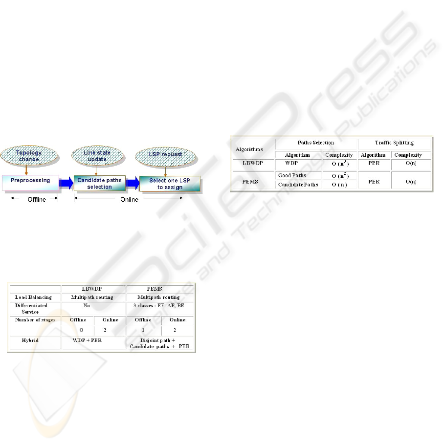
Multipath routing algorithm consists in two main
steps as depicted by Figure 1: computation of mul-
tiple paths and traffic splitting among these multiple
paths. In the first step, it computes the set of candidate
paths which is a subset of all the paths between a pair
of considered routers according to various static cri-
teria such as bandwidth, hop count, delay, error ratio
and so on ...
The second step is to split traffic among multiple
candidate paths. The repartition rate of a demand on
candidate paths depends on the evaluation of dynamic
criteria such as the blockages, the packet loss ratio,
the measured delay, the jitter, and so on ...
2.2 LBWDP (Load Balancing over
Widest Disjoint Paths)
LBWDP (LBWDP, 2005) is a hybrid algorithm that
takes advantages of the path selection of WDP (WDP,
2002) and the splitting mechanism of PER (PER,
2006). For finding the candidate path set, LBWDP
uses the existing WDP (Widest Disjoint Paths) (WDP,
2002) algorithm which focuses on the selection of
good paths. This approach is mainly based on two
concepts: path width and path distance. Path width
is a way to detect bottlenecks in the network and to
avoid them if possible. Path distance is original be-
cause contrary to most approaches, it is not a hop-
count measure but it is indirectly dependent on the
Figure 1: General schema of Multipath routing algorithm.
utilization ratio of each link defining the path. WDP
algorithm performs candidate paths selection based
on the computation of the width of the good disjoint
paths with regard to bottleneck links. The width of a
path is defined as the residual bandwidth of its bot-
tleneck link. The principle of WDP is to select a re-
stricted number of paths. A path is added to the sub-
set of good paths if its inclusion increases the width
of this subset. At the opposite, a path is deleted if this
does not reduce the width of the subset of good paths.
For the traffic splitting stage, LBWDP uses the PER
algoritm (PER, 2006). It consists of two steps: cal-
culating a distribution probability and selecting one
path using Gradient Method with Constraint band-
width traffic. For more details, please refer to (PER,
2006).
This traffic engineering scheme will be useful for re-
ducing the probability of congestion by minimizing
the utilization of the most heavily used link in the net-
work.
2.3 PEMS (PEriodic Multi-Step
Routing Algorithm for DS-TE)
Since MPLS TE (Traffic Engineering based on
MPLS) and DiffServ (Differentiated Services) can be
deployed concurrently in an IP backbone, a proposed
algorithm called PEMS (PEMS, 2006) is useful to
meet the customers’ various requirements and to give
the differentiated services for three classes in the DS-
TE network. Its goal is to develop a routing method
that optimizes differentiation of experienced service
of traffic classes in terms of two metrics, delay and
available bandwidth.
The classes managed by PEMS are: Expedited
Forwarding (EF) for delay sensitive traffic like VoIP
traffic, Assured Forwarding (AF) for soft bandwidth
and loss guarantee traffic like video and Best-Effort
forwarding (BE) for assuring the minimum quality
to best effort service like ftp or e-mail. PEMS aims
basically to minimize the maximum link utilization
over the network, and additionally to give different
service quality to each class, especially to ensure the
ICSOFT 2008 - International Conference on Software and Data Technologies
120
low delay to EF class.
PEMS, has three stages (Figure 2): preprocess-
ing stage, candidate paths computing stage and de-
mand splitting stage for LSP (Label Switched Path)
requests. In the preprocessing stage, it extracts good
paths in order to avoid online searching overhead.
This stage uses only topology information. In the
online mode, when link state information are up-
dated, new candidate paths for each class are calcu-
lated based on updated information such as measured
delay and residual bandwidth. It calculates the split-
ting probability with different weights of delay and
bandwidth depending on the class of requested traf-
fic. When a traffic demand arrives, it performs PER
algorithm (PER, 2006) to select one LSP between the
set of candidate paths to carry current flows. PEMS
aims to minimize the maximum link utilization like
LBWDP algorithm basically, at the same time to give
different service quality to each class, especially to
guarantee the low delay to EF class. For more details
of PEMS, refer to (PEMS, 2006).
Figure 2: Three stages of PEMS.
Figure 3 shows some characteristics for LBWDP
and PEMS from the view point of structure and ob-
jective.
Figure 3: LBWDP and PEMS features.
2.4 Models Scalability and Algorithms
Complexity
The proposed models must have a complexity al-
lowing them to be deployed on complex network
such like internet: it is the scalability problem. The
scalability depends on two factors: the extent of the
deployment and the complexity of the algorithms
that implement the model. In term of deployment,
LBWDP and PEMS reduce the size phenomenon
because they require a full implementation as ingress
routers only. Indeed, in the case of LBWDP, once
the network selects the ingress routers, the role of
the core routers is limited to the implementation of
mechanisms for MPLS. In the case of PEMS, the
core routers are in addition to those mechanisms to
implement the differentiation packages for Diffserv.
So, the scalability of our models is depending
on the algorithms complexity of paths selection and
load balancing algorithms implemented on the ingress
routers. This complexity can be expressed with differ-
ent criteria: the computational time and the memory
space used. In this study, we focus on the computa-
tional time to estimate routing plans after each Link
State Update. This time calculation can be theoreti-
cally approximated by the number of iterations in al-
gorithm. Figure 4 shows the theoretical complexity
of two algorithms depending on the steps that form
them. Thus, we see that the costly steps in terms of
time are those relating to the paths selection.
Figure 4: Algorithms complexity.
3 TOPOLOGY GENERATORS
3.1 Introduction
There are several synthetic topology generators avail-
able to the networking research community (Waxman
(Waxman, 1988), Inet (Inet, 2000), GT-ITM (GT-
ITM, 1997), Tiers (Tiers, 1996), BRITE (BRITE,
2001)..). Many of them differ significantly with re-
spect to the characteristics of the topologies they gen-
erate. An ideal topology generator should enable the
use and development of generation models that pro-
duce accurate representations of Internet topologies.
In this section, we focus on the BRITE generation tool
that we choosed for the simulation after a study and
a comparison done on the set of generators listed be-
fore.
3.2 BRITE
BRITE (BRITE, 2001) is designed to be a flexible
topology generator. As show in Figure 5, it sup-
ports multiple generation models (AS level, Router
PERFORMANCE AND COMPLEXITY EVALUATION OF MULTI-PATH ROUTING ALGORITHMS FOR MPLS-TE
121
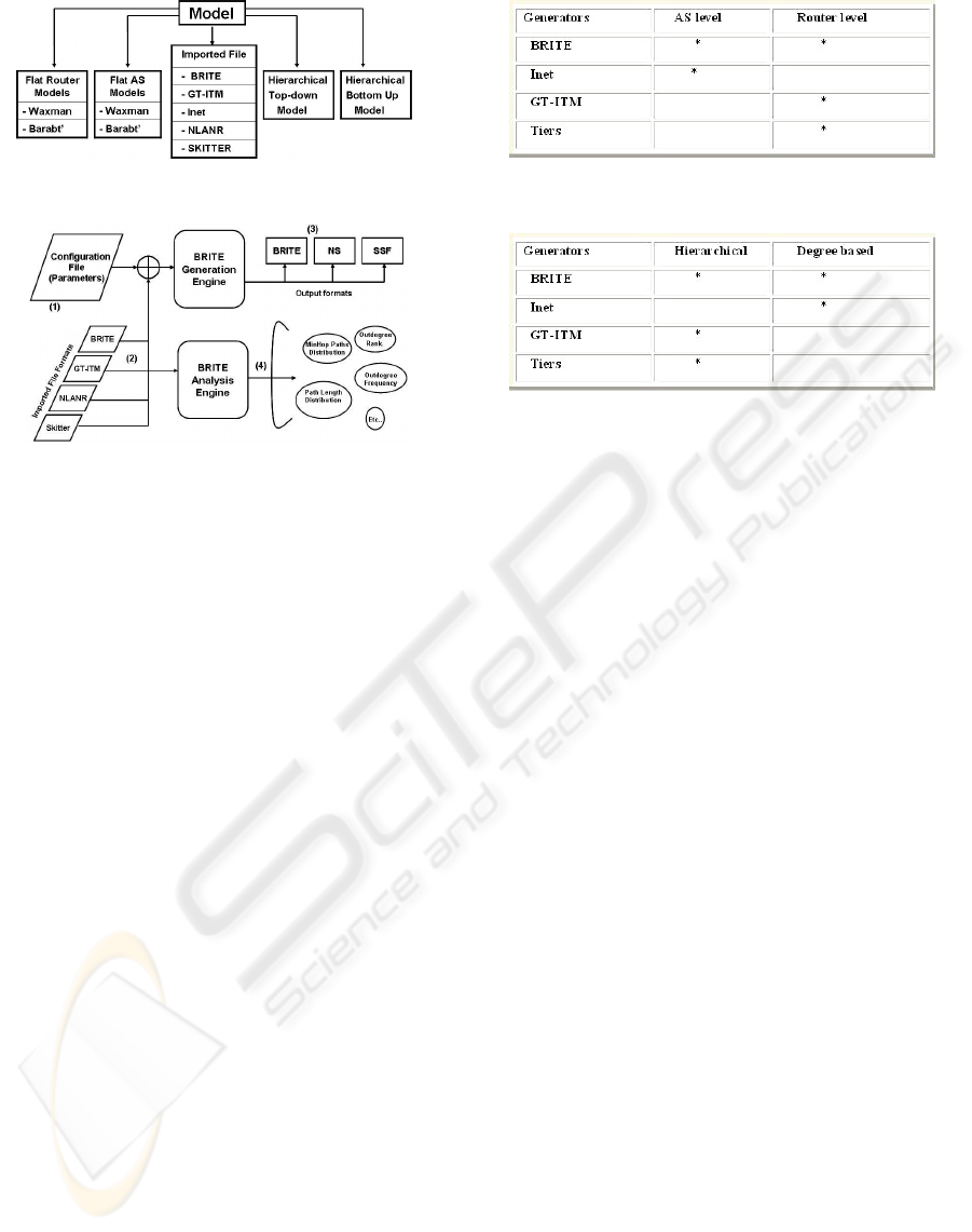
Figure 5: BRITE Structure.
Figure 6: BRITE Architecture.
level, Hierarchical ..) that has several degrees of free-
dom with respect to how the nodes are placed in the
plane (Random or Heavly tailed) and the properties
of the interconnection method to be used (Waxman or
Barabasi-Albert).
Figure 6 shows the main architecture of BRITE.
BRITE reads the generation parameters from a
configuration file (1) that can be either hand written
by the user or automatically generated by BRITE´ s
GUI. It provides the capability of importing topolo-
gies (2) generated by other topology generators
(GT-ITM , Inet , Tiers ) or topological data gathered
directly from the Internet (NLANR (NLANR, 2001),
Skitter (Skitter and McRobb, 2001)). In the current
distribution BRITE produces a topology in its own
file format (3), and it has an output capabilities for
producing topologies that can be used by the Net-
work Simulator (NS2) and the Scalable Simulation
Framework simulators.
Brite has BRITE Analysis Engine or BRIANA (4).
The idea of BRIANA is to provide a set of analysis
routines that may be applied to any topology that can
be imported into BRITE.
The specific details regarding how a topology is
generated depend on the specific generation model
being used. We can think of the generation process
as divided into a four-step process:
1. Placing the nodes in the plane
2. Interconnecting the nodes
3. Assigning attributes to topological
components (delay and bandwidth for
links...)
4. Giving the topology in a specific format
Figure 7: Level comparison.
Figure 8: Model comparison.
BRITE has two very similar implementation
methods (Java and C++) and can be extended by in-
corporating new generation models to its framework.
Since our objective caters to choice the best gen-
erator that represents efficiency and generally the in-
ternet, we present two comparison tables between
BRITE and the other generators based on two criteria:
topology nature and topology level. Figure 7 shows
a comparison in term of generation level. We can
see that BRITE provides a model in two levels: AS
and Router levels, that is not the case for the others.
Similarly, Figure 8 shows that from the view point of
topology nature (Hierarchical or Degree based), only
BRITE implements the 2 models. This two compar-
isons ensure that BRITE correlate closely with real
netwok topologies in term of topology nature and
topology level.
4 SIMULATION MODEL
4.1 Simulation Tools
We used an event-driven network simulator NS2
(NS2, ) to simulate the dynamic nature of a network.
NS2 is developed at the Lawrence Berkeley National
Laboratory (LBNL) of the University of California,
Berkeley (UCB). NS2 has been integrated with the
MNS patch. This patch gives to the simulator a good
support to the establishment of CR-LSP (Constraint
based Routing-Label Switching Path) for QoS traffic
as well as basic MPLS functions as LDP (Label
Distribution Protocol) and label switching.
ICSOFT 2008 - International Conference on Software and Data Technologies
122

As we descriped below, we used BRITE to gener-
ate the simulation topology that must be compatible
with NS2. For this end, we have developped a script
that we called brite2ns that it is capable to generate
a tcl file for each topology used to simulate the algo-
rithms.
4.2 Model
A simulation is defined by an OTcl script. Running a
simulation involves creating and executing files with
a ’.tcl’ extension. For each algorithm, we define three
tcl files.
First we define a Tcl script containing the network
topology generated by BRITE and transformed in
NS2 format by the brite2ns script. This topology in-
cludes the nodes (nodes and MPLS nodes) and links
between nodes. Then we add the routing algorithm
that it is capable to search the all path between each
source/destination pair wich we determine the num-
ber of hopcounts between it. Note that the hop count
determination has little effect in the simulation. We
insert a list of commands to configure the LDP Pro-
tocol, CR-LDP and the MPLS QoS traffic. Multiple
sources of traffic and multiple destinations are con-
nected to some of routers. The link bandwith, the de-
lay and the queue type between two routers are spec-
ified on the link between them. Moreover, the total
parametres are assumed to be the same in all cases to
equalize the topology costs. Parameters used for the
simulation topology are listed in Figure 9.
Figure 9: Topology parameters.
Secondly, we define the traffic class between I/O
LSR. In this tcl file, we determine the time of sim-
ulation, the volume of each individual demand, the
traffic distribution, the start and stop time of a traffic
session and other parametres that specifies each algo-
rithms (Traffic profile in Annex). We simulate all the
algorithms with the same traffic scenario. Figure 10
shows the traffic parametres used for the simulations.
Finally, a tcl script containing the algorithm to
simulate is made, and employed the two tcl scripts
Figure 10: Traffic parameters.
listed below (Topology and Traffic). In this script, we
collects statistics and outputs the results of the simu-
lation. Results are usually written to files, including
files for Nam.
5 EVALUATION AND ANALYSIS
5.1 Evaluation Criteria
The main purpose of Traffic Engineering and Diff-
Serv is to control the end-to-end quality by improving
an efficiency use of network resources. An evaluation
that considers both viewpoints is necessary. It is also
necessary to evaluate the scalability of our algorithms.
For this simulation experiments, end-to-end delay and
link utilization are chosen to be the performance met-
rics of interest. The link utilization which is good to
be a performance metric is selected to show whether
the network load is well balanced. End-to-end delay
is added as a new performance metric in this simu-
lation to estimate whether delay-sensitive traffic, EF
traffic, can be guaranteed its appropriate service. To
estimate delay, queue monitor is used in NS simulator.
5.2 Evaluation Graphs and Results
The simulation has been made with the purpose of a
differents numbers of highly redundant nodes MPLS
network core, basically to studying the response of
the algorithms on the topology increase, specifically
in term of network use and end-to-end quality.
We simulate topologies with a growing number
of nodes (100, 200 and 300). The graphs were
made from data obtained by the simulations of these
different topologies, and they are placed in scales in
3D form to better analyze and compare the results.
We can analyze the load-balancing capacity of two
models using the figures 11, 12 and 13. These figures
give us respectively as function of time, the maximum
rate utilization of different topologies links for each
model. They show that LDWDP gets more efficient
result for load balancing than PEMS and it seems
PERFORMANCE AND COMPLEXITY EVALUATION OF MULTI-PATH ROUTING ALGORITHMS FOR MPLS-TE
123
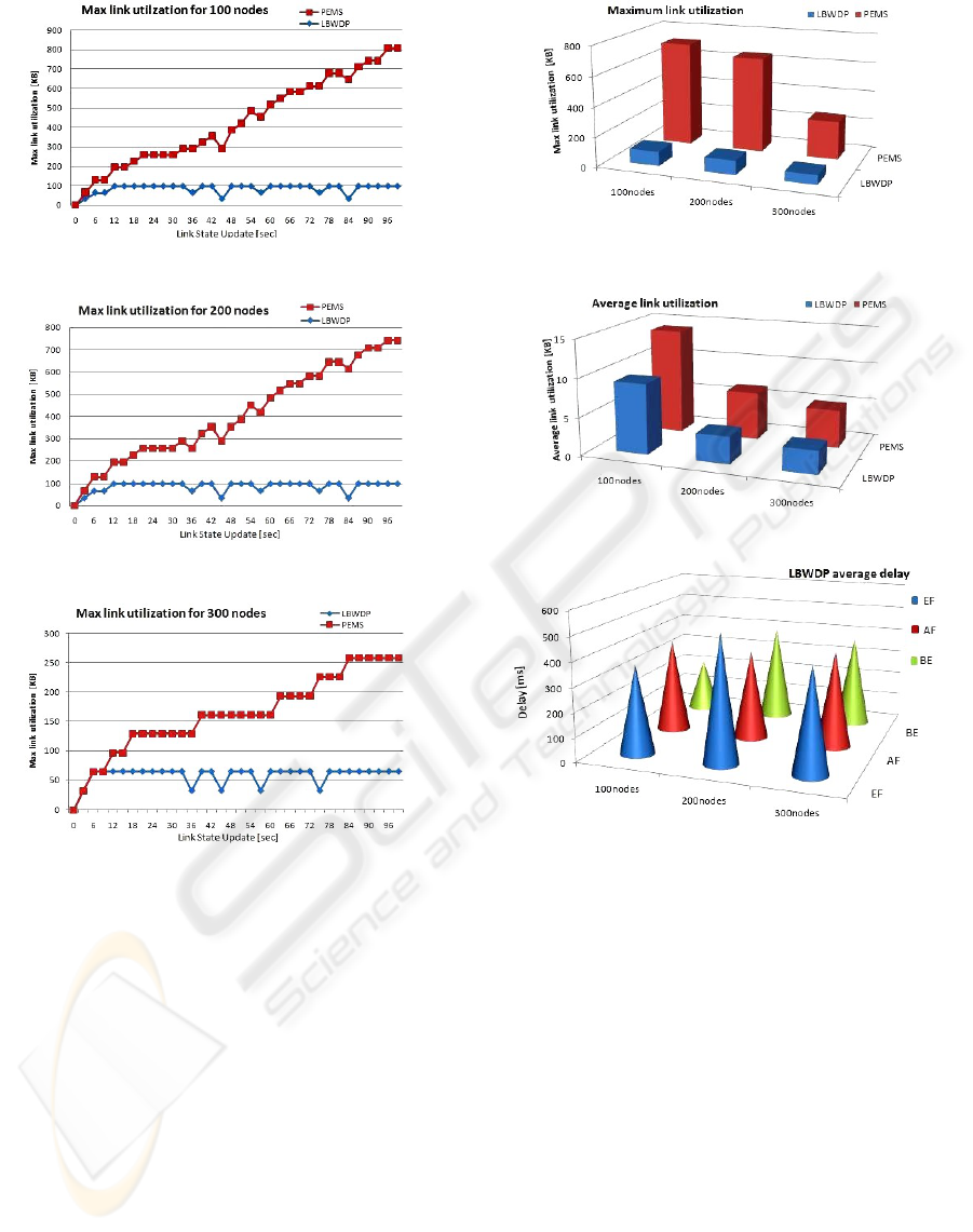
Figure 11: Maximum link utilization for 100 nodes.
Figure 12: Maximum link utilization for 200 nodes.
Figure 13: Maximum link utilization for 300 nodes.
more scalable, we can see easily that the links are less
saturated with LBWDP than PEMS.
As regards the maximum utilization (Figure 14),
LBWDP takes the minimum ”maximum utilization”
throughout all topologies simulated, and it is clear
from the difference between the scales of two mod-
els, which is also constant throughout all topologies
from 100 to 300 nodes, that the load through the net-
work still well balanced with LBWDP than PEMS.
This result can be explained by the fact that PEMS
is more complex than LBWDP especially in paths se-
lection part or in promosing certain paths to specific
traffic classes like EF that needs a low delay.
Elsewhere, this conclusion is confirmed by the
analysis of the average link utilization for the two
models (Figure 15). In this figure, we can observe that
the gap between the scales of two models is smaller
than that in the case of the maximum link utiliza-
Figure 14: Maximum link utilization.
Figure 15: Average link utilization.
Figure 16: LBWDP average delay.
tion, which expresses the proper load balancing of
LBWDP that distributes better the load on the set of
links. We remark also that the scales degrade less
and less from 100 nodes to 300 nodes, that may be
referring to the fact that when the number of nodes
increases, the possibility to get better paths increases
also.
By contrast, as regards the delay, if we look at the
graphs in figures 16 and 17, we remark that PEMS
(Figure 17) can differentiate the measured delay ac-
cording to each class of traffic and it gives the best
delay for the EF traffic in contrast with LBWDP (Fig-
ure 16) that gets results for all classes indifferently
and it didn’t privilege the EF traffic. This tendency is
also confirmed by the perturbation of LBWDP scales
in figure 16 from 100 to 300 nodes, against a remark-
able stability of PEMS scales in Figure 17.
ICSOFT 2008 - International Conference on Software and Data Technologies
124

Figure 17: PEMS average delay.
6 CONCLUSIONS
In this paper, we have described and evaluated a
framework consisted of two algorithms (LBWDP and
PEMS), and concentrated on load balancing for pro-
viding QoS and TE objective through the multipath
routing in the IP-based MPLS and DS-TE network.
We simulate them using a single topology each time
for 3 cases (100, 200 and 300 nodes), a single sig-
nalling protocol and a single type of traffic. By sim-
ulation, LBWDP gets more efficient result for load
balancing than PEMS. We have showen that LBWDP
can balance the load and minimize the maximum link
utilization better than PEMS because it does not con-
cern a specific class, while PEMS can differentiate the
measured delay according to the class, that LBWDP
gets the results for all classes indifferently. Other sim-
ulations represent subject to an actual work will be
presented in future papers.
In the future, we will integrate other load balancing
algorithms for MPLS TE and DS-TE and we will
compare them for the view point of scalability and
end-to-end quality with increasing the topology level
to prove and determine which algorithm is the best.
Also, PEMS can be improved by adapting dynami-
cally the parametres of the traffic splitting stage de-
pending on the network state, or extended for more
traffic classes. Other combinations could be made
in the future, per example the combination of WDP,
first step of LBWDP, with the traffic splitting part of
PEMS. A research is in way to implemente this work
in the ad hoc wireless technology.
REFERENCES
BRITE (2001). Boston university representative internet
topology generator. Computer Science Department
Boston University.
DS-TE. Mpls traffic engineering–diffserv aware (ds-te). In
CISCO.
GT-ITM (1997). Modeling internet topology. IEEE Trans-
actions on Communications.
IETF. In http://www.ietf.org/.
Inet (2000). Inet: Internet topology generator. University
of Michigan.
LBWDP (2005). Stable load balancing algorithm in mpls
network. In K. Lee, A. Rahmani, A. Toguyeni. LAGIS,
Ecole centrale de Lille.
MPLS (2001). Multiprotocol label switching architecture.
In http://ietf.org/rfc/rfc3031.txt. IETF.
NLANR (2001). National laboratory for applied network
research (nlanr). http://moat.nlanr.net/rawdata/.
NS2. The network simulator. http://www.isi.edu/nsnam/ns/.
PEMS (2006). Pems, a periodic multi-step routing algo-
rithm for ds-te. LAGIS, Ecole centrale de Lille.
PER, K. L. (2006). Global qos model in the isp networks:
Diffserv aware mpls traffic engineering. LAGIS,
Ecole centrale de Lille.
Skitter, C. and McRobb (2001). Measurement and vi-
sualization of internet connectivity and performance.
http://www.caida.org/Tools/Skitter.
Tiers (1996). A better model for generating test networks.
IEEE GLOBECOM.
Waxman, B. (1988). Grouting of multipoint connections.
IEEE J. Select. Areas Commun.
WDP (2002). On selection of paths for multipath routing. In
S. Nelakuditi and Z.i Zhang. University of Minnesota.
APPENDIX
Figure 18: EF Traffic in Time/Traffic source.
PERFORMANCE AND COMPLEXITY EVALUATION OF MULTI-PATH ROUTING ALGORITHMS FOR MPLS-TE
125
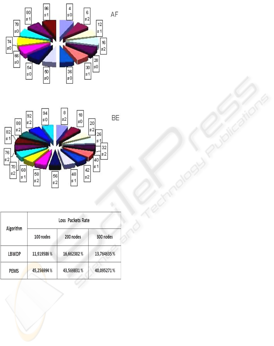
Figure 19: AF Traffic in Time/Traffic source.
Figure 20: BE Traffic in Time/Traffic source.
Figure 21: Loss packets Rate.
ICSOFT 2008 - International Conference on Software and Data Technologies
126
