
ON THE CLARIFICATION OF THE SEMANTICS OF THE
EXTEND RELATIONSHIP IN USE CASE MODELS
Miguel A. Laguna and José M. Marqués
Department of Computer Science, University of Valladolid
Campus M. Delibes, 47011 Valladolid, Spain
Keywords: Use case, extend relationship.
Abstract: Use cases are a useful and simple technique to express the expected behavior of an information system in
successful scenarios or in exceptional circumstances. The weakness of use cases has been always the vague
semantics of the relationships, in particular the extend relationship. The main contribution of this article is
an attempt to clarify the different interpretations that can be adopted. A major revision of the UML standard
would be impractical, but the extension point concept could be completed, including minimum and
maximum multiplicity attributes. Using these minor changes, the legal combination of base/extending use
cases in the requirements models would be unequivocally defined. Therefore, the ambiguity of the original
UML models would be removed.
1 INTRODUCTION
Use cases are one of the preferred techniques for the
elicitation and definition of the intended behavior of
the system under study. They are a useful and simple
technique to describe the successful scenarios
(where things occur as expected) or the problematic
situations (alternative and exceptional paths). Use
cases were an original idea of Jacobson,
incorporated in his OOSE development method
(Jacobson et al., 1994). From the first versions of
UML as standard modeling language (Rational
Software Corporation, 1997), use cases have been
chosen as the preferred technique to identify and
define the user requirements and to represent the
behavior of the system as a black box, in place of
other techniques used until then; for example, the
Rumbaugh OMT method (Rumbaug et al., 1991)
used data flow diagrams. They are basic in the
Unified Process, as this was evolved from the ideas
of Jacobson (Rumbaugh et al., 2004). Many
criticisms have been made concerning use cases; see
for example the articles of Berard (Berard, 1995),
Simons (Simons, 1999), or more recently Isoda
(Isoda, 2003). Conversely, there are many works
that try to improve or at least clarify them, such as
the classical book of Cockburn (Cockburn, 2000) or
the work of Williams (Williams et al., 2005 ).
Some authors have suggested that the most
important characteristics of use cases are the textual
details to be discussed with the end users while
neglecting the visual representation and semantics
proposed by UML. Others, such as Rumbaugh and
Jacobson, continue to promote the graphics aspects
(Rumbaugh et al., 2004). Constantine connects user
interface design methods with the use case
elicitation and refinement (Constantine and
Lockwood, 1999). Some additional relationships and
other different meta-model modifications are
proposed. More details about these questions can be
found in the related work section.
One of the major controversies is the UML’s
explanations of include and extend relationships.
These concepts remain vague, and apparently
contradictory, confusing readers (and also some
authors of software engineering books) about when
to use include or extend. Precise and unambiguous
definitions of terms are missing in the numerous
UML documents. Therefore, UML's explanations for
include and extend relationships are still subject to
ongoing debate. Some conferences have been
devoted to these and other conflicting aspects
(Génova et al., 2004).
The rest of the paper is as follows: The next
section briefly summarizes the evolution of include
and extend relationships in UML documents.
Sections 3 and 4 specifically discuss the problems
72
A. Laguna M. and M. Marqués J. (2008).
ON THE CLARIFICATION OF THE SEMANTICS OF THE EXTEND RELATIONSHIP IN USE CASE MODELS.
In Proceedings of the Third International Conference on Software and Data Technologies - SE/GSDCA/MUSE, pages 72-79
DOI: 10.5220/0001889800720079
Copyright
c
SciTePress
with the extend relationship and propose some
semantic reinterpretations and minor meta-model
modifications. Section 5 presents related work and
section 6 concludes the paper and proposes
additional work.
2 THE EVOLUTION OF THE
EXTEND RELATIONSHIP
It is well known that a use case describes an
interaction between one or more actors and the
system as a sequence of messages. Thus, a use case
diagram has two types of nodes: actors and use
cases, connected by association relationships. The
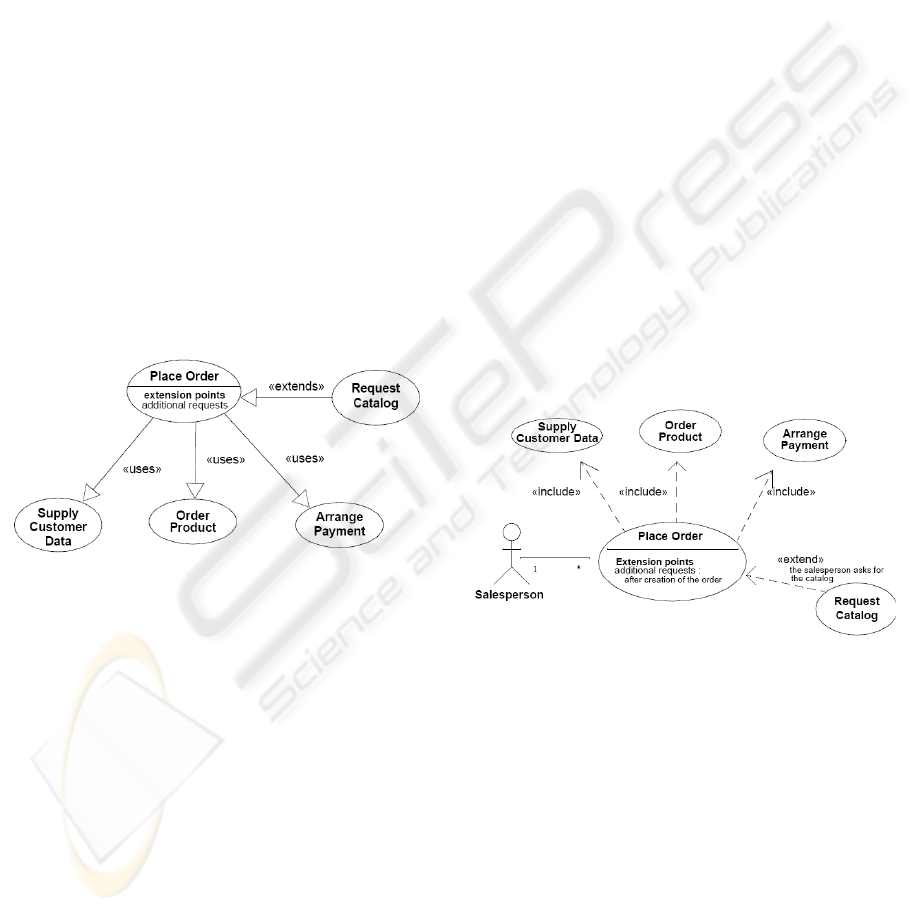
original proposal of Jacobson also included two
kinds of relationships between use cases: The uses
and extends relationships, indicated with
generalization arrows. This syntax was initially
preserved in primitive UML versions (see Figure 1)
but, beginning with the refined 1.3 version, a new
set of relationships was proposed and this definition
has essentially been kept, with minor changes, until
the actual UML 2.1.1 version.
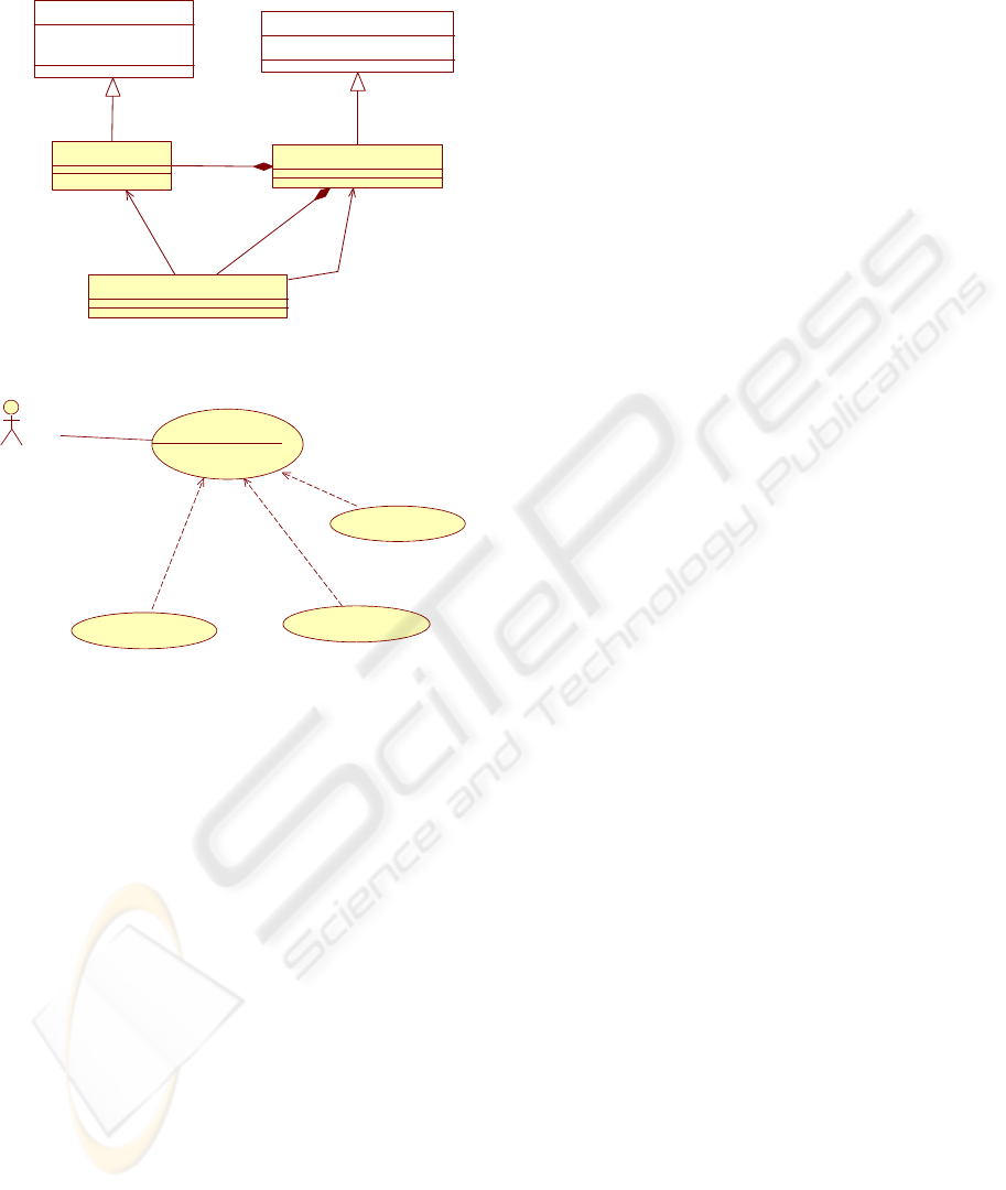
Figure 1: The syntax of the old extends and uses
relationships, as exemplified in the 1.1 version of UML
(Rational Software Corporation, 1997).
From UML 1.3, relationships between use cases
can be expressed in three different ways: with
generalization, include, and extend relationships (see
Figure 2 for extend and include examples):
• A generalization relationship between use cases
implies that the child use case contains the
behavior of the parent use case and may add
additional behavior.
• An include relationship means that the behavior
defined in the target use case is included at one
location in the behavior of the base use case (it
performs all the behavior described by the
included use case and then continues with the
original use case).
• An extend relationship defines those instances
of a use case that may be augmented with some
additional behavior defined in an extending use
case.
The semantics of include relationship has always
been reasonably clear. However, the extend
relationship has generated a lot of controversy. The
variety of diverse interpretations that different
authors use in textbooks or research papers is
surprising, but it is less surprising if we read some
fragments of the description of the UML 1.3
“clarifying” description:
“An extend relationship defines that a use case
may be augmented with some additional behavior […].
The extend relationship contains a condition and
references a sequence of extension points in the target
use case. […] Once an instance of a use case is to
perform some behavior referenced by an extension
point of its use case, and the extension point is the first
one in an extend relationship’s sequence of references
to extension points, the condition of the relationship is
evaluated. […] Note that the condition is only
evaluated once: at the first referenced extension point,
and if it is fulfilled all of the extending use case is
inserted in the original sequence. An extension point
may define one location or a set of locations in the
behavior defined by the use case. However, if an extend
relationship references a sequence of extension points,
only the first one may define a set of locations. […]”
Figure 2: The syntax of the actual extend and include
relationships, as they appear in the 2.1.1 version of UML
(Object Management Group, 2007).
Several modifications have been added to the
different versions of UML. Attempts at removing
these difficulties have been proposed in these
documents. From here until the end of the article,
we base the discussion on the official UML
documentation, version 2.1.1 (Object Management
Group, 2007). Figure 3 shows the Use Case Package
of UML 2.1.1 superstructure meta-model.
ON THE CLARIFICATION OF THE SEMANTICS OF THE EXTEND RELATIONSHIP IN USE CASE MODELS
73
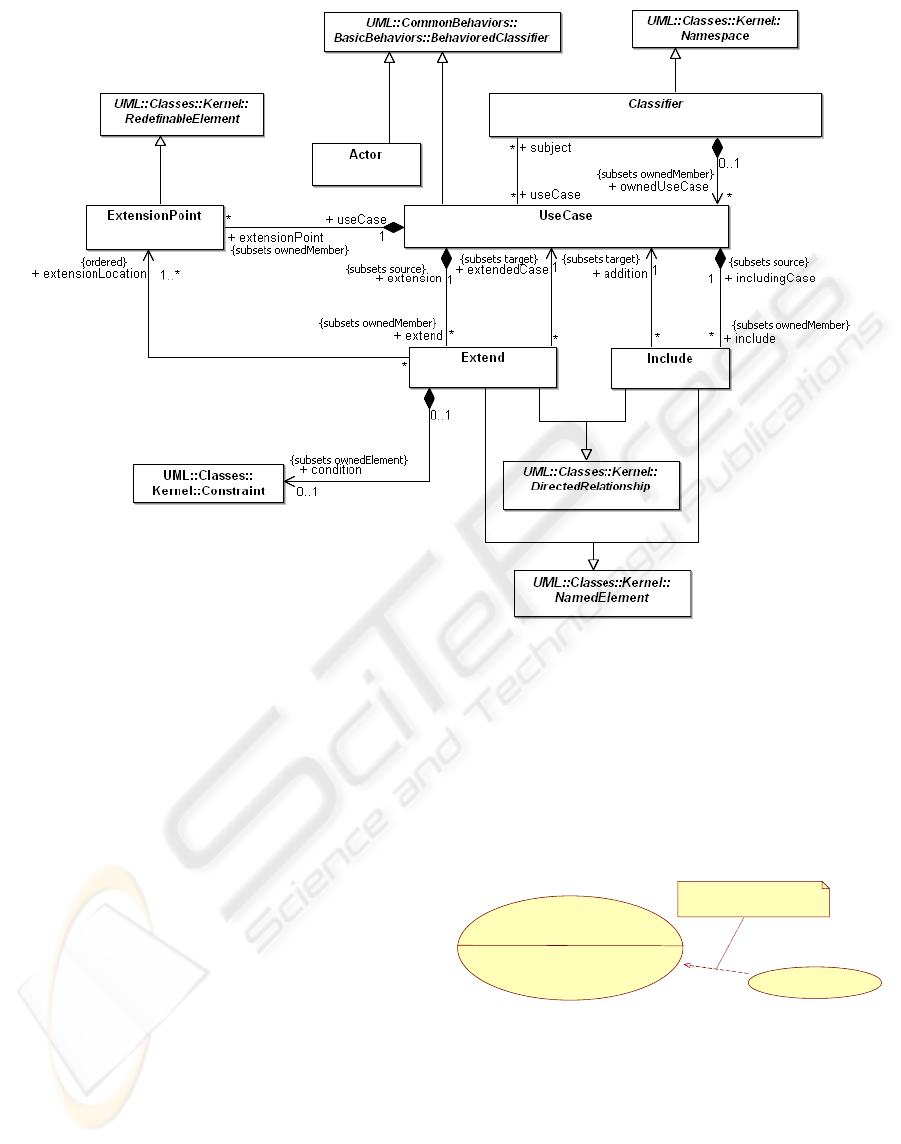
Figure 3: The Use Case Package of UML 2.1.1 Superstructure meta-model (Object Management Group, 2007).
In the UML 2.1.1 meta-model, Actor and
UseCase are both BehavioredClassifier, which itself
is a descendent of Classifier. This is problematic for
use cases, as a use case describe a set of interactions
more than a set of instances (Génova and Llorens,
2005). Some changes have been incorporated from
version 2.0 to 2.1. Actor in UML 2.0 was simply a
Classifier, not a BehavioredClassifier. These
variations make it difficult to understand the
semantics of the meta-model.
As UML documentation states, the extend
relationship specifies how and when the behavior
defined in the extending use case can be inserted
into the behavior defined in the extended use case (at
one extension point). Two important aspects are: a)
this relationship is intended to be used when some
additional behavior can be added to the behavior
defined in another use case; b) the extended use case
must be independent of the extending use case.
Analyzing the meta-model, the extension-
Location association end references the extension
points of the extended use case where the fragments
of the extending use case are to be inserted. An
extensionPoint is an owned feature of a use case that
identifies a point in the behavior of a use case where
it can be extended by another use case. The extend
condition is an optional Constraint that references
the condition that must hold for the extension to take
place. The notation for conditions has been changed
in UML 2: the condition and the referenced
extension points is included in a Note attached to the
extend relationship (Figure 4).
Perform ATM Transaction
Selection
extension points
On Line Help
<<extend>>
Condition:{HELP selected}
extension point: Selection
Figure 4: The extend and condition representation in UML
2.1.1 (Object Management Group, 2007).
Semantically, the concept of an “extension
location” is left underspecified in UML because use
cases “are specified in various idiosyncratic
formats”. UML documentation refers to the typical
textual use case description to explain the concept:
“The use case text allows the original behavioral
description to be extended by merging in
ICSOFT 2008 - International Conference on Software and Data Technologies
74
supplementary behavioral fragment descriptions at
the appropriate insertion points”. Thus, an extending
use case consists of behavior fragments that are to be
inserted into the appropriate spots of the extended
use case. An extension location, therefore, is a
specification of all the various (extension) points in
a use case where supplementary behavioral
increments can be merged.
The next sections are devoted to analyzing this
relationship and the connected extension point
concept. First, we assume the UML meta-model and
consider the different semantic interpretations of the
extension concept and the way the ambiguity can be
removed. Then, in section 4, we discuss the
necessity of the extension point concept itself.
3 THE INTERPRETATION OF
THE EXTENSION POINT
CONCEPT
In this section, we assume that the extension point is
a valuable concept and analyze the different possible
interpretations, trying to remove ambiguity.
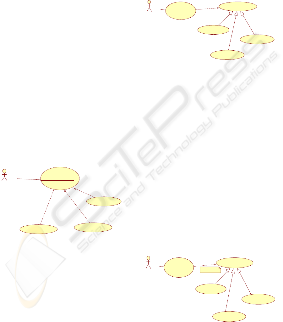
Consider the typical example of Figure 5, where a
Process Sale use case has an extension point
Payment and several use cases extend the use case at
this point.
Cashier
Process Sale
Payment
extension points
Cash Payment
Credit Payment
Check Payment
<<extend>>
<<extend>>
<<extend>>
Figure 5: The Use Case Process Sale, extended by three
alternative (?) use cases.
The question is: What exactly does the extension
point Payment mean? Is it a blank space that must be
compulsorily refilled? And, if this is true, is it
correct to add the behavior of only one of the three
use cases or is it legal to add the consecutive
behavior of two of these? For instance, if one and
only one of the use cases must be selected, we really
have a sort of polymorphism, as Figure 6 tries to
show. Really, the syntax of the figure is correct from
the point of view of UML 2. The imagination of the
modeler can add the rest: the fragments of the
Cash/Credit/Check Payments use cases can
substitute the sort of interface that the Process
Payment use case represents, and this last is needed
to complete the behavior of the Process Sale use
case.
We think that it is necessary to clarify the
different possibilities that can appear in a system:
Cashier
Process Sale
ProcessPayment
<<include>>
Cash Payment
Credit Payment
Check Payment
Figure 6: The Use Case Process Sale and a possible
interpretation of the Process Payment extension.
1) The situation is well established from the very
beginning, as in the preceding example. The
requirements for a simple store could be “All
sales imply a method of payment” and “Only
one payment method can be authorized”. In
these over-simplified situations, Figure 6 states
clearly the semantics of the real behavior better
than the pure extend relationship.
2) The situation is well established, extension is
mandatory but flexible. The requirements could
be: “All sales imply at least one method of
payment”. The problem now is that we cannot
directly express this difference in the diagram.
An illegal (i.e., not present in the UML meta-
model) multiplicity annotation in the include
relationship could help (see the interpretation of
Figure 7). Otherwise, a change of the include
relationship from a stereotyped dependence to
an association could solve the problem. Really,
the evolution of the original uses relationship to
a dependence relationship with the new name
include was a conflicting choice in the old
UML1.1 to UML1.3 transition time.
Cashier
Process Sale
Process Payment
Cash Payment
Credit Payment
Check Payment
<<include>>
1..* {illegal}
Figure 7: The Use Case Process Sale and a reinterpretation
of the Process Payment extension as a relationship with
explicit multiplicity.
ON THE CLARIFICATION OF THE SEMANTICS OF THE EXTEND RELATIONSHIP IN USE CASE MODELS
75
3) Other situations can be predictable but not
mandatory (“the SalesPerson can ask for the
catalog” as in the example of Figure 2). In this
case, the semantics correspond to an optional
behavior in a specific point of the extended use
case (“after creation of the order”). We need
here all the assortment of details: extension
point declaration, extending use case and
constraint.
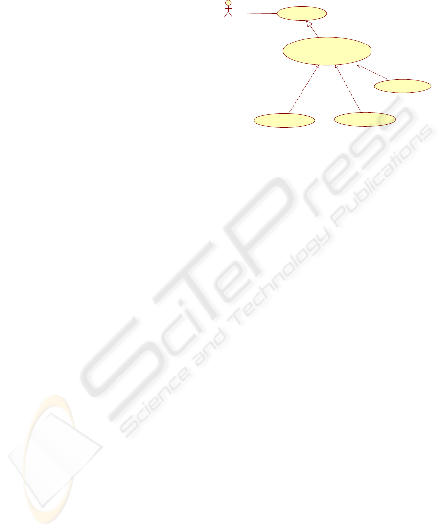
4) The last possibility, nearest to the original
extend semantics, is that the situation that we
want to solve is completely open in an
unexpected way. In this case, the mere inclusion
of an extension point in the “perhaps may be
extended in the future” use case is
contradictory. We do not know if any step of the
use case description will have an alternative
path a posteriori. The proposal is that we do not
need any extension point; the “may be
extended” use case must be able to be added as
a special step in the exception/alternative paths
set. This links to the next section’s discussion
and the solution proposed there: do not specify
extension points (we cannot do it in any case as
we cannot anticipate all the possible behavior
modifications). The interpretation can be made
explicit with the example in Figure 8. A new
use case is added, based (via a generalization
relationship) on the original unchanged use
case. This new version has all the steps of the
old use case and the new extension point. Now,
the additional behavior can be connected via the
extend relationship. As in the first and third
variants, only the possibilities of the current
UML meta-model are exploited. However, the
problematic of the three possible variants
considered in the previous situations (always
one extension, at least one, zero or more) must
be solved.
Summing up, we can use the elements of the
UML meta-model to specify most of the situations,
except for that stated in the second point (mandatory
but flexible extension). We reach a crossroads. The
radical proposal would be to modify completely the
UML use case package, clarifying its general
semantics and syntax (and this is a long awaited
demand of many requirements specialists, as the
related work section will make clear). The pragmatic
possibility is to keep the actual Use Case Package,
while suggesting minor changes. This implies facing
two different problems: well known extensible
situations (this problem refers to situations 1, 2 and
3) and unpredictable extensions (situation 4).
Solving the first problem, the second is solved in
two steps, as explained above, following the scheme
of Figure 8.
Advanced Process Sale
Payment
extensionpoints
Cash Payment
Credit Payment
Check Payment
<<extend>>
<<extend>>
<<extend>>
Process Sale
Figure 8: The Use Case Process Sale and a reinterpretation
of the Process Payment extension as an a posteriori
addition.
To solve the first set of situations, removing any
ambiguity from the visual representation of the
model, we need to complete the diagram with
multiplicity details: The proposal consists of
minimally modifying the UML meta-model, adding
a generalization relationship from ExtensionPoint to
MultiplicityElement from the Multiplicity Package.
This solution implies that the ExtensionPoint meta-
class would now have the lower and upper attributes
(Figure 9). The advantage of this solution is that the
meta-model is not essentially changed. But the
extension point would have additional and clarifying
information, which allows us to assign an integer
value to the new lower and upper ExtensionPoint
attributes:
• 0..1 multiplicity states that the extending use
case is added only in certain circumstances
(when the constraint condition is true). This is
equivalent to the actual semantic
interpretation given by UML documentation.
• 1..1 multiplicity states that one of the possibly
n extend use cases can be inserted. At the
same time, the constraint conditions of each
extend use case cannot overlap (See Figure
10).
• 1..n (with n>1) multiplicity allows more than
one use case to add behavior to the original
use case (in our example, two consecutive
payment kinds can be authorized).
The remaining possibility (situation 4, open to
extension in any unexpected way) can be handled
using the generalization relationship, as in Figure 8,
combined with the modified semantics of the
extension point. We believe that the combination of
the two interpretations covers all the practical
ICSOFT 2008 - International Conference on Software and Data Technologies
76
situations and solves the problems that the
requirements engineers face in their daily work.
MultiplicityElement
+/upper: U nlimitedNat ural
+/lower: Integer
Extend
ExtensionPoint
BehavioredClassifier
+ownedBehavior(): Behavior
UseCase
+extend
+extendedCase
+extensionLocation
Figure 9: The Use Case Package with multiplicity added.
Cashier
Process Sale
Payment [1..1]
extension points
Cash Payment
Credit Payment
Check Payment
<<extend>>
<<extend>>
<<extend>>
Figure 10: The Use Case Process Sale, extended by three
alternative use cases.
4 DISCUSSION
The previous section has shown that the use of the
extension point concept is problematic and must be
dealt with carefully. In this section, we try to answer
an earlier question: Is the presence of the extension
point concept in the use case models really
indispensable? From the point of view of the
semantics of the dependence relationship, the mere
presence of an extension point in the base use case is
confusing. To remove (or perhaps to reinterpret) the
extension point concept could perhaps be a way of
avoiding many problems.
The first intention of a dependence relationship
is to establish a directed relationship between an
independent element (the base or extended use case)
and a dependent element (the extending use case).
Therefore, if the base use case must have no
information a priori about the extending use case,
the obligation of predetermining an extension point
is contradictory. The well known open-closed
principle states that (generally speaking) a piece of
software must be completely closed from the point
of view of the existing clients (in this case, the rest
of software artifacts: classes, sequence diagrams or
simply requirements documentation artifacts) and
open to possible enhancements for new clients (new
requirements or enhancements). This idea typically
applies to inheritance relationships between classes
in object oriented designs but can also be adopted in
requirements artifacts.
The types of problems we want to solve are, for
example: a use case can evolve during the
development of several versions of a software
system; the requirements can change; new
constraints or business rules can appear, etc. The
essence of these situations is that the evolution
usually occurs “in an unexpected way”. While the
user requirements are being elicited, we have a
possible solution with plain use cases: add an
alternative sequence of steps to the set of exceptions
of the use case, referring to a step of the main
scenario. The generalization of the idea is exactly
the extension concept, useful when a) the use case is
already completely developed through a
collaboration that involves analysis or design
models, or b) the complexity of the steps that must
be added recommends separating this piece of
behavior in a new use case. In both cases, as in the
plain solution, we must be able to indicate where the
new sequence must be inserted (after the original
step n) and where the original scenario must
continue (after the original step m). This can be as
complex as needed, as in the idea of extension points
with several fragment insertions.
Surprisingly, the concept of step is not directly
present in the UML meta-model Use Case Package,
probably in order to allow different particular
implementations (visual or textual, formal,
structured or informal). Really, a Behaviored-
Classifier has an associated Behavior that can have a
set of atomic actions or states … and this could be
identified as the steps of the sequence of messages
of the original textual use cases. However,
independently of the concrete format, the concept of
sequence of steps should have to be present (or
specialized as in other packages) in this meta-model
Package.
As we do not foresee immediate changes in the
UML meta-model, we can suggest an apparently
inaccurate solution to deal with this problem:
consider that a use case has a set of steps (or
sequence of inseparable steps) called extension
points. If we think this way, quite simply, all the
steps of a use case are extensible. This interpretation
ON THE CLARIFICATION OF THE SEMANTICS OF THE EXTEND RELATIONSHIP IN USE CASE MODELS
77

implies that the use cases are completely open to
future extensions (in the same way an unaffected
class can be extended by a new one using
inheritance in object oriented languages). Really, our
intention is only conceptual: the details are in the
textual step-based description of the use cases. In
practical terms, this supposes that the extension
point concept is not used in the diagrams. In the
textual documentation of the extending use case, we
must indicate:
a) The use case modified.
b) The fragment/step where the extended use case
is modified, using the same conventions of
the alternative/exception fragments of the
monolithic use cases; in other words, the
precise step number must be referred.
c) The “return point” of the extended use case in
order to continue with the normal sequence of
steps.
The adoption of this approach means that all the
possible situations must be documented in the
textual information of the extending use case. The
extended use case remains unchanged and unaware
of the extensions.
Summarizing the idea, in many cases (in
particular in agile developments), it is preferable not
to use extension points with the original UML
semantics (or the modified version suggested in this
article). Or, changing the point of view, all the steps
of a use case can be considered as extension points.
This version smooths the learning curve of the
technique by beginners (in fact we use this approach
with our undergraduate students, avoiding many
confusing discussions in the requirements gathering
sessions).
5 RELATED WORK
Many criticisms of and suggestions for modification
of the UML meta-model have been proposed,
including the use of ontologies instead (Genilloud
and Frank, 2005). Some additional relationships
between use cases have been proposed, such as the
precedes relationships from the OPEN/OML method
(Henderson-Sellers and Graham, 1997). Rosenberg
(Rosenberg and Scott, 1999) uses the precedes and
also the invokes constructs to factor out common
behavior. Conversely, other authors such as Larman
(Larman, 2004) advocate not using the extend
relationship or using only when it is undesirable to
modify the base use case.
The BehavioredClassifier specialization of the
use cases has been analyzed in (Génova and Llorens,
2005): The Behavior meta-class is a specification of
how its context classifier (use case) changes over
time and the BehavioredClassifier is a classifier that
can have behavior specifications. In other words, a
BehavioredClassifier is rather an ordinary classifier
that can own behaviors (Génova and Llorens, 2005).
The conclusion is that the formalization of use cases
as classifiers in UML has obscure points: Two
contradictory notions of use cases coexist in UML 2:
“set of interactions” vs. “set of entities”. The authors
propose the meta-model should be changed to make
UseCase a subtype of Behavior, not of
BehavioredClassifier. Alternatively, they admit that
the meta-model may be kept as it is, but it should be
recognized that a use case is the specification of a
role. Williams et al. also analyze the UML 2 meta-
model and propose changing UseCase to a subclass
of Behavior (Williams et al., 2005 ).
Isoda states that UML 2 has a correction about
the relationship between use cases and actors, which
effectively means that UML has finally abandoned
the idea of “actors call operations of a use case”, but
the details of UML 2 in fact still retain those defects
(Isoda, 2003).
Jacobson believes that integrating use cases and
aspect oriented programming (AOP) will improve
the way software is developed. The idea is to slice
the system and keep the use cases separate all the
way down to the code. “In the long term we will get
more of extension-based software-extensions from
requirements all the way down to code and runtime;
and extensions in all software layers, for example,
application, middleware, systemware, and
extensions across all these layers” (Jacobson, 2003).
Braganza et al., discuss the semantics of use case
relationships and their formalization using activity
diagrams in the context of variability specification.
They propose an extension to the extend relationship
that supports the adoption of UML 2 use case
diagrams into model driven methods. The proposal
results from the 4 Step Rule Set, a model driven
method in which use cases are the central model for
requirements specification and model transformation
(Braganca and Machado, 2006).
The common conclusion of most of the work
done in use case semantics is that the question is not
well solved in UML and a redefinition of the
concepts is needed. We believe that our contribution
can help in this redefinition.
ICSOFT 2008 - International Conference on Software and Data Technologies
78

6 CONCLUSIONS
In this article, the problems of interpretation of the
extend semantics in use case models are analyzed.
The possible situations are studied and an
interpretation is given for each of them. A possible
improvement of the extension point concept is
proposed, assuming that the use of this construction
is useful in certain circumstances. The multiplicity
attributes added to the extension point suppose a
clarification of the expected behavior it is possible to
add in those places. We think that, without
neglecting major future modifications in the UML
meta-model, this slight change can help in the
process of elicitation and specification of functional
requirements, clarifying the intention of the final
users.
We have implemented the modified meta-model
(really the Ecore version of UML meta-model) with
the GMF/Eclipse platform. The building of a set of
experimental mini-CASE tools (we are only
interested in the use case diagrams) is a work in
process to check the usefulness of the approach. The
intention is to use this tool with undergraduate
students and validate the comprehension of the
multiplicity attribute in the extension point concept.
ACKNOWLEDGEMENTS
This work has been supported by the Junta de
Castilla y León project VA-018A07.
REFERENCES
Berard, E. (1995). Be Careful with Use Cases. Technical
report.
Braganca, A., and Machado, R. J. (2006). Exending UML
2.0 Metamodel for Complementary Usages of the
«extend» Relationship within Use Case Variability
Specification. Proceedings of the 10th international on
Software Product Line Conference. IEEE Computer .
Cockburn, A. (2000). Writing Effective Use Cases.
Addison-Wesley Professional .
Constantine, L., and Lockwood, L. (1999). Software for
Use. Addison-Wesley.
Genilloud, G., and Frank, W. F. (2005). Use Case
Concepts from an RM-ODP Perspective. Journal of
Object Technology, vol. 4, no. 6, Special Issue: Use
Case Modeling at UML-2004 , 95-107.
Génova, G., and Llorens, J. (2005). The Emperor’s New
Use Case. Journal of Object Technology, Vol. 4 No. 6,
Special Issue: Use Case Modeling at UML-2004 , 81-
94.
Génova, G., Llorens, J., Pierre Metz, R. P.-D., and
Astudillo, H. (2004). Open Issues in Industrial Use
Case Modeling. The 7th International Conference on
the Unified Modeling Language-UML'2004 Satellite
Activities. Lisbon, Portugal, October 11-15.
Henderson-Sellers, B., and Graham, I. (1997). The OPEN
Modeling Language (OML) Reference Manual. SIGS
Books.
Isoda, S. (2003). A Critique of UML’s Definition of the
Use-Case Class. Proceedings of 6th International
Conference on the Unified Modeling Language, (pp.
280-294).
Jacobson, I. (2003). Use Cases and Aspects—Working
Seamlessly Together. Journal of Object Technology,
(www.jot.fm), July/August .
Jacobson, I., Booch, G., and Rumbaugh, J. (1999). The
Unified Software Development Process. Addison-
Wesley.
Jacobson, I., Christerson, M., Overgaard, P., and Jonsson,
G. (1994). Object-Oriented Software Engineering, A
Use Case Driven Approach. AddisonWesley.
Larman, C. (2004). Applying UML and Patterns: An
Introduction to Object-Oriented Analysis and Design
and the Unified Process (3rd Edition). Addison
Wesley.
Object Management Group. (2007). Unified Modeling
Language: Superstructure, version 2.1.1. formal doc.
2007-02-05.
Rational Software Corporation. (1997). Unified Modelling
Language Version 1.1.
Rosenberg, D., and K. Scott. (1999). Applying Use Case
Driven Object Modeling with UML: A Practical
Approach. Addison Wesley.
Rumbaugh, J., Blaha, M. P., William, E. F., and Lorensen,
W. (1991). Object-Oriented Modeling and Design.
Prentice Hall.
Rumbaugh, J., Jacobson, I., and Booch, G. (2004). The
Unified Modeling Language Reference Manual (2nd
Edition). Addison-Wesley Professional.
Simons, A. J. (1999). Use Cases Considered Harmful.
29th Conf. Tech. Obj.-Oriented Prog. Lang. and Sys.,
(TOOLS-29 Europe). IEEE Computer Society.
Williams, C., Kaplan, M., Klinger, T., and Paradkar, A.
(2005). Toward Engineered, Useful Use Cases.
Journal of Object Technology, Vol. 4, No. 6, Special
Issue: Use Case Modeling at UML-2004 , 45-57.
ON THE CLARIFICATION OF THE SEMANTICS OF THE EXTEND RELATIONSHIP IN USE CASE MODELS
79
