
VISUAL ABSTRACT NOTATION
FOR GUI MODELLING AND TESTING
1
VAN4GUIM
Rodrigo M. L. M. Moreira and Ana C. R. Paiva
Faculty of Engineering of the University of Porto, Informatics Engineering Department
Rua Dr. Roberto Frias, s/n, 4200-465 Porto, Portugal
Keywords: GUI modelling, Visual GUI modelling, GUI testing, Test coverage criteria, UML Profiles.
Abstract: This paper presents a new V
isual Notation for GUI Modelling and testing (VAN4GUIM) which aims to
hide, as much as possible, formalism details inherent to models used in model-based testing (MBT)
approaches and to promote the use of MBT in industrial environments providing a visual front-end for
modelling which is more attractive to testers than textual notation. This visual notation is developed as five
different UML profiles and based on three notations/concepts: Canonical Abstract Prototyping notation;
ConcurTaskTrees (CTT) notation; and the Window Manager concept. A set of translation rules was defined
in order to automatically perform conversion from VAN4GUIM to Spec#. GUI models are developed with
VAN4GUIM notation then translated automatically to Spec# that can be then completed manually with
additional behaviour not included in the visual model. As soon as a Spec# model is completed, it can be
used as input to Spec Explorer (model-based testing tool) which generates test cases and executes those tests
automatically.
1
Work partially supported by FCT (Portugal) under
contract PTDC/EIA/66767/2006.
1 INTRODUCTION
GUI testing is an area of increasing importance,
where the tests are performed from the end users
point of view. Software companies have the best of
interests on finding defects on their products before
their costumers’ do, not only to meet user demands
and therefore increase confidence in relation to their
software, but also to induce correctness and
commitment with them. For these reasons, GUI
testing is extremely necessary. It is particularly time
consuming, labour-intensive, expensive and
difficult. Presently used GUI testing methods are
almost ad hoc and require test engineers to manually
develop the necessary scripting to perform test
execution, and though evaluate if the GUI is
effectively tested. However, there are some tools
that can help improving GUI testing process. Some
of these tools exploit a broadly accepted method that
generates GUI test scripts which relies on the
capture/playback technique. Such technique requires
testers to perform labour-intensive interaction with
the GUI via mouse events and keystrokes. During
interaction user events are recorded into scripts
which and can be automatically played later for GUI
testing. However, when different inputs are required
to conduct the test or even if the GUI changes, it is
then required to re-generate the test scripts. In
addition, it is hard to cover all possible test cases for
all GUI components and capture/playback method
often records redundant data (Utting and Legeard,
2007).
The use of a model to describe the behaviour of a
system is an established and key advantage
regarding testing. Models can be used in numerous
ways, for instance, to improve quality of software
documentation, code generation and test case
generation. Model-based testing represents the
automation of the design of black-box tests. The
usage of a model to describe the behaviour of a GUI
in combination with an automated test tool to
generate test cases, execute those tests and report
104
M. L. M. Moreira R. and C. R. Paiva A. (2008).
VISUAL ABSTRACT NOTATION FOR GUI MODELLING AND TESTING - VAN4GUIM.
In Proceedings of the Third International Conference on Software and Data Technologies - SE/GSDCA/MUSE, pages 104-111
DOI: 10.5220/0001894001040111
Copyright
c
SciTePress

errors found, can dramatically reduce the time
required meant for testing software.
In recent times, model-based testing has been
receiving attention due to the potential to automate
test generation and increasing model driven software
engineering practices. Nevertheless, the usage of
uncommon modelling notations, the lack of
integrated tool environments and support, the
difficulties inherent to the constructions of models,
the test case explosion problem, the gap between the
model and the implementation, remain as obstacles
regarding the adoption of model-based GUI testing
approaches. In addition, the models used are often
textual models and usually testers and modellers
prefer working with visual/graphical notations.
The goal of this research work is to
Develop a visual modelling front-end hiding
as much as possible the formal details from
modellers and testers.
Define a set of rules to translate the visual
notation into Spec# (Barnett et al., 2005) (an
extension of C# with contracts).
Develop a tool to automate the translation
from visual model to Spec# and ensure
consistency between both models.
2 STATE OF THE ART
In current times, GUIs play an important role in
most of software systems, as they represent the
fore-front of systems. UML is a natural candidate for
GUI modelling since it represents a standard
notation for object-oriented modelling of
applications. GUIs can be decomposed in two main
groups: a dynamic or behaviour group and a static
or layout group (Blankenhorn and Walter, 2004).
While the dynamic group can be modelled using
existing UML diagrams and elements, GUI layout
cannot, due to the fact that all existing UML
diagrams are not layout-aware. In addition, it is not
clear and simple to identify how UI elements, such
as user tasks and display, are supported by UML. As
such, it is necessary to make use of UML extension
mechanisms, like constraints, tagged values, and
stereotypes, in order to provide more flexibility to
the existing UML notation. With these extension
mechanisms it becomes possible to style several
UML profiles for GUI modelling.
2.1 UML Profile for GUI Layout
Several researchers have recognized the lack of
support for layout information in UML and thus
have taken different approaches. Kai Blankenhorn
and Wilhelm Walter (Blankenhorn, 2004) have
developed an UML Profile for GUI Layout, which is
a UML 2.0 profile that uses Diagram Interchange to
store layout information while staying fully conform
to standards. The diagram-interchange specification
originates XMI from the XML metadata interchange
format, which is used for storing information about
the elements of a UML diagram. The profile’s
meta-model makes use of stereotyped classes that
are linked by constrained associations, taking benefit
from UML 2.0 extension mechanisms. In order to
improve the usefulness of the graphical language
and to transfer the general look of designer sketches
to models, the authors have developed a set of
stereotype icons. They claim that their approach
yields benefits for those involved in the design
process of GUIs. Designers are their main audience.
The profile is best suited for creating an initial
model of the layout and navigational concept of the
application. However it does not model the
behaviour of the GUI.
2.2 UMLi
The UMLi notation (Silva and Paton, 2000) aims to
be a light-weight extension to the UML notation
with the purpose to provide greater support for UI
design, becoming possible to model both behaviour
and structure of a system. However, modelling the
behaviour of a system via UMLi is not indeed
straightforward due to its complexity. UMLi
notation has been influenced by model-based user
interface development environment (MB-UIDE)
technology. In addition, the authors of UMLi believe
that the MB-UIDE technology offers many insights
into the abstract description of user interfaces that
can be adapted for use with the UML technology,
such as techniques for specifying static and
dynamic aspects of user interfaces using declarative
models. The notation defines three distinct types of
models: presentation model, domain model and
behaviour model. The presentation model
represents the visual part of the user interfaces that
can be modelled using object diagrams composed of
interaction objects. Domain models specify classes
and objects that represent the system entities, the
domain elements. Behaviour models describe object
collaboration and common interaction behaviour,
such as tasks, actions and events.
2.3 Wisdom Profile
The Wisdom Profile is proposed by Nunes and
Cunha (Nunes and Cunha, 2000), for the
VISUAL ABSTRACT NOTATION FOR GUI MODELLING AND TESTING - VAN4GUIM
105

documentation, specification and design of
interactive systems. They propose a minimal set of
extensions for a UML profile for interactive systems
development taking advantages of human-computer
interaction domain knowledge under the notation
and semantics of the UML. The Wisdom approach
suggests two important models: the analysis model
and the interaction model. The latter includes the
information, dialogue and presentation dimensions,
mapping the conceptual architectural models for
interactive systems, while maintaining the desired
separation of concerns. The analysis model
encompasses the UML profile architecture and
shared information. During the design phase, the
interaction model embraces two other models: the
dialogue model and the presentation model. The
former specifies the dialogue structure of the
application, using an UML based approach of the
ConcurTaskTrees (CTT) notation. The latter defines
the physical realization of the interactive system,
centring on the structure of the different presentation
entities in order to realize the physical interaction
with the user. The authors propose a set of UML
extensions to support the design model.
2.4 usiXML
usiXML (User Interface eXtensible Markup
Language) is a XML-compliant markup language
that describes the User Interface (UI) for multiple
contexts of use such as Character User Interfaces
(CUIs), Graphical User Interfaces (GUIs) and
Multimodal User Interfaces (Vanderdonckt et al.,
2004). With usiXML it becomes possible to specify
a user interface at different levels of abstraction
while maintaining the mappings between those
levels, whenever required. This notation is based on
five main concepts: expressiveness of UI (depends
on the context of use), central storage of models,
transformational approach (each model may be
subject to several transformations supporting various
development keys), multiple development paths, and
flexible development approaches (top-down,
bottom-up, wide-spreading). The main audience for
usiXML are analysts, modellers, designers, and
others.
2.5 Canonical Abstract Components
The concept of abstract user interface prototypes
offers designers a form of representation for
specifying and exploring visual and interaction
design ideas that are between abstract task models
and realistic or representational prototypes. They
represent an intermediate form that can speed the
user interface design process and improve the
quality of the result. As abstractions, they can serve
as an intermediate bridge between task models and
realistic designs, smoothing, simplifying, and
systematizing the design process. Canonical
Abstract Prototypes (CAP) are an extension to
usage-centred design which provides a formal
vocabulary for expressing visual and interaction
designs without concern with details of appearance
and behaviour. CAPs embody a model specifically
created to support a smooth progression from
abstraction toward realization in user interface
design. Each Canonical Abstract Component is
comprised by a symbolic graphical identifier and a
descriptive name. The graphical symbols aim to
serve as learned shorthand for the various functions
available. The notation is quite simple, since it is
built on two basic symbols: a generic tool or action
and a generic material or container. Materials are
the containers, content, information or data. Tools
are the actions, operators, mechanisms, or controls
that can be used to create, manipulate, transform or
operate upon materials. The combination of a
container and an action form a generic hybrid
component.
2.6 ConcurTaskTrees
The ConcurTaskTrees (CTT) is one of the most
widely used notations for task modelling,
specifically tailored for UI model-based design. This
notation has been developed taking into account the
previous experience in task modelling and adding
new features to better obtain an easy-to-use powerful
notation, to describe the dialogue in interactive
systems. In fact, CTT provides the concept of
hierarchical structure, exposing a wide range of
granularity allowing large and small structures to be
reused and, enables reusable task structures to be
defined at both low and high semantic level. CTT
introduces a rich set of graphical temporal operators,
with a higher expressiveness than those offered by
concurrent notations. In a model-based GUI testing
approach, task models can be used to define the
behaviour of user interfaces (Silva et al., 2007).
2.7 Spec#
The Spec# programming system represents an
attempt to develop a more cost effective way to
maintain software in high standards, and has been
developed at Microsoft Research lab, in Redmond,
USA. The Spec# system consists of three
ICSOFT 2008 - International Conference on Software and Data Technologies
106
components: the Spec# programming language, the
Spec# compiler, and the Spec# static program
verifier (Barnett et al., 2005). The Spec#
programming language extends the existing object-
oriented .NET programming language C# and
expands the type system to include non-null types
and checked exceptions. It also provides method
contracts in the form of pre- and post-conditions,
and also invariants. Since all of the specifications
written in Spec# may be executable, it is possible to
specify invariants, pre- and post-conditions, and
executable method bodies in a high-level action
language, with primitives to change the value of
state variables, and even call external methods
defined in .NET assemblies. Spec# provides the
ability to build a formal specification of an
interactive application, describing the actions that a
user may perform when interacting with the system,
in the terms of changes to the state of the
application. Using Spec#, one can build a formal
specification of an interactive application, describing
the actions a user can perform at each moment, and
the expected effect of each user action, in terms of
changes to the state of the application (according to
a model of the application state as perceived by the
user) and possible effects to the environment (Paiva,
2007). The effect of user actions may depend not
only on the current state of the application, but also
on environment conditions. The state of the
application is described by means of state variables.
The GUI Spec# models can be used as input to
Spec Explorer (Campbell et al., 2005) (model-based
testing tool) which generates test cases and executes
those tests automatically.
3 VAN4GUIM OVERVIEW
The VAN4GUIM (Visual Abstract Notation for GUI
Modelling) was developed based on UML extension
mechanisms, UML Profiles. An UML Profile can be
useful for building UML models for particular
domains. They are based on stereotypes and tagged
values that are applied to elements, attributes,
methods, links, and link ends. Those extensions
together with added restrictions define UML
meta-models that can be used to construct models
for such particular domains.
The VAN4GUIM UML Profiles are based on
three notations/concepts:
Canonical Abstract Prototyping which is a
notation introduced by Larry Constantine
(Constantine, 2003). The prototypes are an
extension to usage-centred design that provide
a formal vocabulary for expressing visual and
interaction designs without concern for details
of shape and behaviour.
A commonly accepted and widely applied
notation, ConcurTaskTrees (CTT) (Paternò
et al., 1997), which initial goal was to support
designers of interactive systems. The CTT is a
notation for task modelling being able to
graphically represent a hierarchical structure,
with a set of temporal operators capable of
describing concurrent behaviour.
Window Manager Concept is useful to
describe the common behaviour of windows
showing up and disappearing during the
execution of a window application.
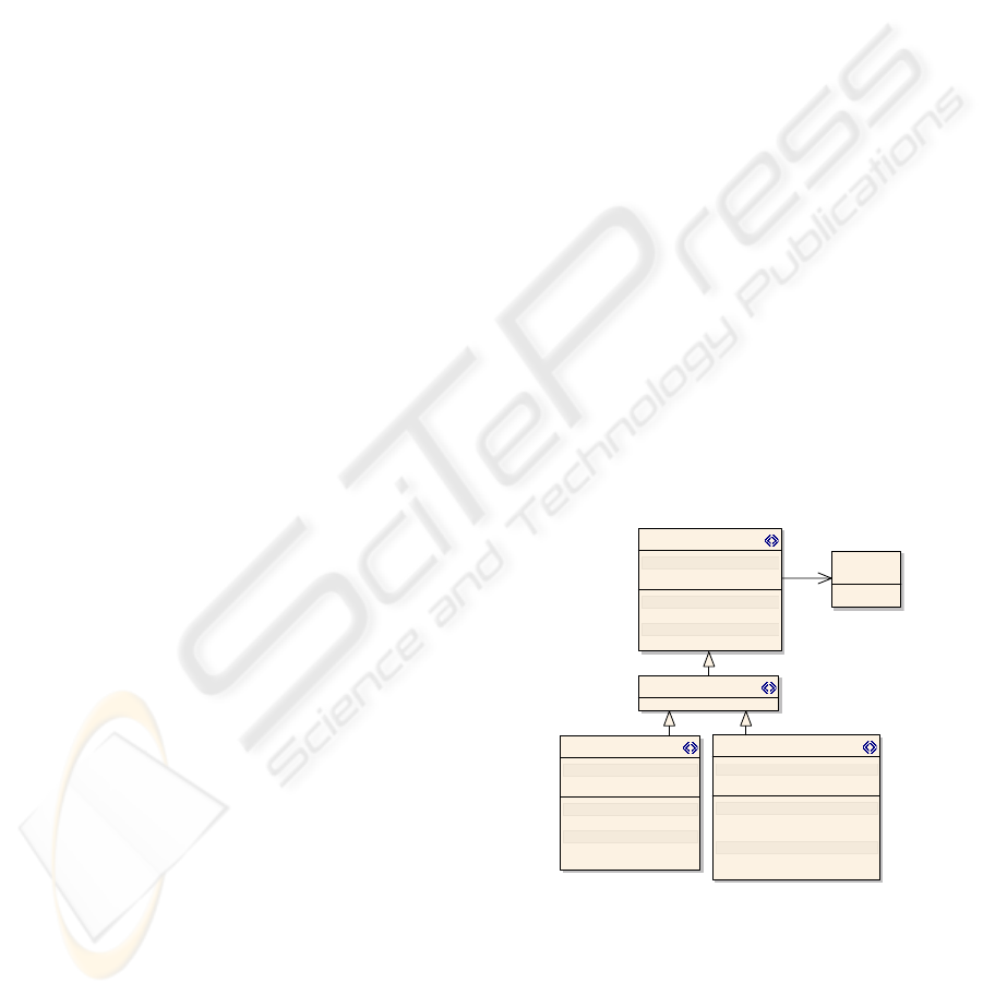
The Canonical Abstract Prototyping notation was
extended with behaviour (state, properties with
associated set and get methods (Figure 1), methods
and restrictions such as pre- and post-conditions)
and the CTT notation was extended with restrictions
over the operators which define how to use them
correctly (from the VAN4GUIM point of view).
VAN4GUIM is composed of five different UML
Profiles:
Containers – Is a subset of Canonical
Abstract Components which act as holders of
user interface objects (generically called
DataStores). A Container extends DataStore
and can hold an object (Element) or a set of
objects (Collection) (Figure 1).
Collection
«Property»
# elements: Set of Object = {}
«property get»
+ Getelements() : Seq of Object
+ Isenabl ed() : bool ean
«property set»
+ Setelements(Seq of Object) : void
+ Setenabled(bool ean) : voi d
Contai ner
«Property»
# enabled: bool ean = True
«property get»
+ Isenabl ed() : bool ean
«property set»
+ Setenabled(boolean) : void
Element
«Property»
- state: Object
«property get»
+ Isenabl ed() : bool ean
«property set»
+ Setenabled(bool ean) : voi d
«metaclass
»
Da ta S to re
E d it a ble
«extends»
Figure 1: Containers UML Profile.
User Actions – Is a subset of Canonical
Abstract Components which represent tools
(actions, operators, mechanisms, or controls)
that can be applied upon containers
(generically called InteractionFunctions). An
Action extends InteractionFunction and can
VISUAL ABSTRACT NOTATION FOR GUI MODELLING AND TESTING - VAN4GUIM
107
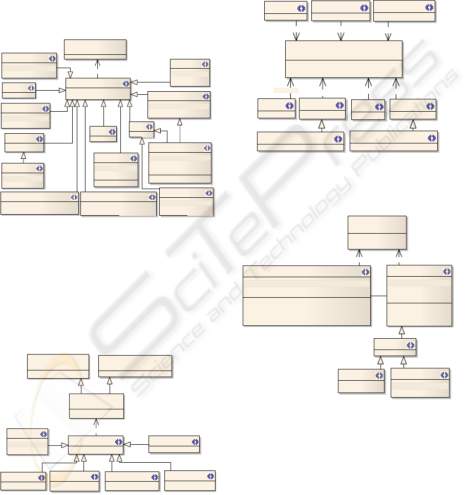
model several different user actions, such as,
Modify, which updates an Editable container,
and Move, which moves an object from a
source to a target object (Figure 2). Move has
additional restrictions to model behaviour,
such as, its parameters cannot be null
(represented by an exclamation mark "!" at the
of the parameter's type) and a pre-condition
stating that the source should be different from
the target (source != target).
Select
«Pro p erty»
- state: SelectableCollection
Duplicate
+ DuplicateObj(object!, object!) : void
Toggle
«Property»
- state: boolean
Mov e
+ PerformMove(object!, object!) : void
Action
«metaclass»
InteractionFunction
View
«Pro p erty»
- state: Collection
+ ViewAction() : void
Start
«Property»
- state: Collection
Stop
Modify
«Property»
- state: Editable
Create
«Property»
- state: InputAccepter
Delete
Perform
Delete
«Property»
- state: EditableElement
Delete
«Property»
::Se lect
- state: SelectableCollection
+ DeleteSelection() : void
Start
«extends»
Figure 2: User Actions UML Profile.
Hybrids – Are combinations of DataStores
and InteractionFunction (Figure 3). They are
used to model user actions that take place over
specific containers. For instance, a
SelectableCollection is the combination
between a Collection Container and a Select
Action (Figure 2) which is per si a restriction
on its behaviour.
«metacl ass»
Contai ner s:: Da taStore
«metaclass»
User Acti ons::Interacti onFuncti on
«metaclass»
Interaction
Activ eMaterial
I nputAcc epte r
«Property»
+ content: object
EditableElement
EditableCollection
SelectableCollection
SelectableActionSet
SelectableViewSet
«extends»
Figure 3: Hybrids UML Profile.
CTT Connectors – Is based on CTT notation
and describes relationships between two
elements of the VAN4GUIM (Figure 4). E.g.,
the EnablingWithInfoExchange connector
transfers information between its source and
its target and, at the same time, sets the
enabled property of the target to true. This is
described by the following post-condition
source.enabled == true.
«metaclass»
Connector
+ direction: Di rection = Source -> Desti...
+ ki nd: ConnectorKi nd
Hierarchy
Enabling
Choi c e
EnablingWithInfoExchange
OrderInde pe ndency
Concurrent
ConcurrentWi thInfoExchange
Disabling
Suspend/Resume
«extends» «extends»
«extends»
«extends»
«extends»
«extends»
«extends»
Figure 4: CTT Connectors UML Profile.
Window Manager – To describe the
windows' behaviour (Figure 5).
Manager
«Property»
- WindowMapping: Map<Window, WindowInf> = {|->}
+ AddWindow(Window, WindowInf) : void
+ IsEnabled(Window) : void
+ IsOpen(Window) : void
+ RemoveWindow(Window) : void
Window Inf
«Property»
- isModal: boolean
- parent: WindowInf
+ GetName() : string
+ GetParent() : WindowInf
+ GetType() : boolean
«metaclass»
Window
+ enabled: boolean
+ name: String
AckMsgBox
+ Ack() : voi d
QueryMsgBox
«Property»
+ answer: Set<object>
Notification
1 0..*
«extends»«extends»
Figure 5: Window Manager UML Profile.
VAN4GUIM profiles extend UML state
machines by allowing states to represent, for
instance, user actions and transitions to represent
restrictions between the executions of two user
actions (e.g., concurrent transitions mean that the
two states linked by these transitions may be
executed in any order).
The behaviour added to the VAN4GUIM
notations is taken into account by the translation
process to Spec#.
ICSOFT 2008 - International Conference on Software and Data Technologies
108
4 GUI MODEL
The GUI model constructed in VAN4GUIM is a
state machine diagram in which states can be
instances of any element within Containers, User
Actions, Hybrids and Window Manager Profiles.
Transitions between states are elements within CTT
Connectors Profile.
A GUI model constructed in VAN4GUIM
notation will have, at least, two levels:
A Navigation map diagram – this diagram
shows the set windows of the GUI and the
possible transitions between them which
represent the possible actions the users can
perform to open/close a specific window of
the GUI.
Behaviour of each Window – this diagram
describes the behaviour of each window, e.g.,
the containers and the set of actions the user
can perform and the relationship between
elements of the diagram. At this level of
abstraction, it is possible to have AckMsgBox
and QueryMsgBox but it is not possible to
have other kind of windows from the Window
Manager Profile.
However, situations may occur where more than
two model levels can be useful. It is responsibility of
the modeller to decide how many levels the GUI
model should have.
5 VISUAL TO TEXTUAL
TRANSLATION RULES
GUI models constructed based on VAN4GUIM are
translated to Spec# textual notation according to
some rules that are presented next. The behaviour
within the GUI model and GUI Profiles are taken
into account.
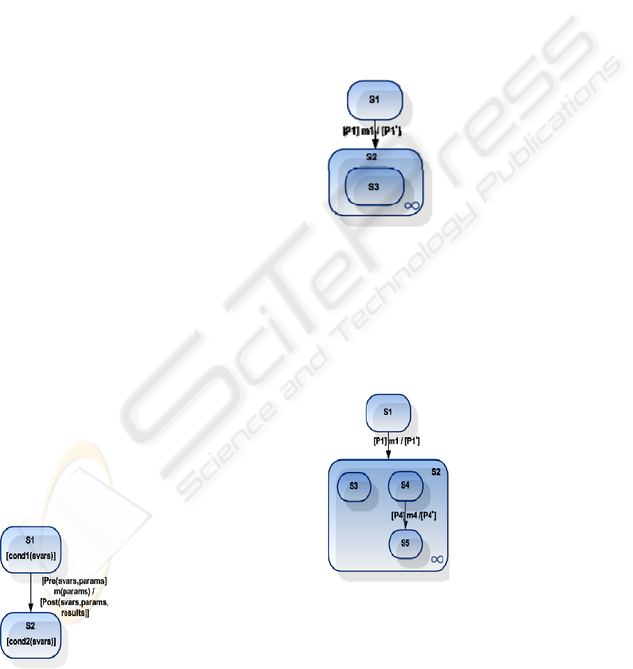
5.1 Simple Transition
[Action] m(params)
requires cond1(svars)
&& Pre(svars,params);
ensures
Post(svars,params,results)
&& cond2(svars); {
//TODO
}
S1 and S2 represent an instance of a stereotype
available from any of the Profiles defined.
In order to simplify the state machines and
expressions, from now on, it is assumed that Si is a
condition over state variables in state i; whenever
states represent windows, Ni is the name of the
window i and [Pi]mi/[Pi'] are transitions between
states in which [Pi] is a pre-condition over state
variables and parameters, mi is a function with
(omitted) parameters and [Pi'] is a post-condition
over state variables, parameters and result of the
executed function.
5.2 Transition to a Composite State
namespace N1;
using WindowManager;
[Action] m1
requires S1 && [P1];
ensures [P1'] && S2
&& S3; {
AddWindow(N2,(true,S1));
//TODO
}
S1 and S2 are instances of the windowInf stereotype;
S3 can be any instance of any stereotype of any
profile (except a windowInf).
5.3 Transition to a Composite State
with Two or More Possible Initial
States
namespace N1;
using WindowManager;
[Action] m1
requires S1 && [P1];
ensures [P1'] && S2
&& S3 && S4; {
//TODO
}
namespace N2;
using WindowManager;
[Action] m4
requires S4 && [P4]
ensures [P4’] && S5 {
//TODO
}
S1 and S2 represent instances of windowInf
stereotype; S3, S4 and S5 can be instances of any
stereotype of any profile (except windowInf).
This rule can be generalized to any number n of
initial states inside S2. In this case, the
post-condition of m1 should be
VISUAL ABSTRACT NOTATION FOR GUI MODELLING AND TESTING - VAN4GUIM
109
[P1'] && S2 && S3 && S0 &&...&& Sn && S4
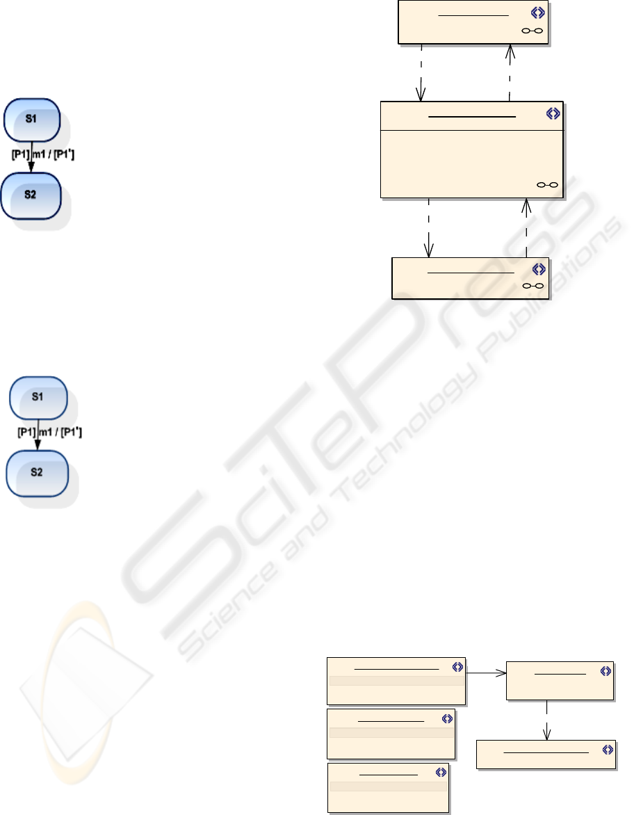
5.4 Transition to a Acknowledge
Message State
[Action] m1
requires S1 && [P1];
ensures [P1'] && S2 &&
IsOpen(N2);{
AddWindow(S2,(true,S1));
//TODO
}
[Action] Ok
requires IsOpen(N2);
ensures [P1’] && !IsOpen(N2);{
RemoveWindow(N2);
//TODO
}
S1 represent an instance of any stereotype of any
profile; S2 is an instance of the stereotype
AckMsgBox (modal window).
5.5 Transition to an Alert Message
State
[Action] m1
requires S1 && [P1];
ensures [P1'] && S2 &&
IsOpen(N2); {
AddWindow(N2,(true,S1));
//TODO
}
[Action]ChooseOp(string op)
requires IsOpen(N2) && S2;{
//TODO
}
S1 is an instance of any stereotype of any profile
(except windowInf). S2 is an instance of the
QueryMsgBox stereotype (modal window).
States inside composite states can be again
composite states, in which case translation rules 5.2
and 5.3 may be applied, or single states in which
case any other translation rule different from 5.2 and
5.3 may be applied.
A GUI model is finite, it cannot have infinite
composite states inside composite states, so the
translation process is also finite.
6 CASE STUDY
The Microsoft Notepad text editor is used to
illustrate the approach.
Tagged values are translated to instance variables
(e.g., fileName, and text in Notepad window).
Sav eAs :WindowInf
Notepad :WindowI nf
tags
exit = false
fileName = "'"
fi ndWhat = '"'
text = ""
Find :WindowInf
Save
«Concurrent»
SaveAs
«EnablingWithInfoExchange»
Cancel
«Concurrent»
Fi nd
«Enabl ingWithInfoExchange»
Figure 6: Part of the Navigation map.
The Spec# specification generated automatically
from the diagram in Figure 6 is listed below.
namespace Notepad;
using WindowManager;
//state variables
string fileName = "";
string text = "";
// Actions
[Action]
public void Find_Cancel_Notepad()
requires IsEnabled("Find");
ensures !IsOpen("Find”);
{ //TODO }
[Action]
public void Notepad_Find_Find()
requires IsEnabled("Notepad") && text != ""
&& !IsOpen("Replace");
ensures Find.findWhat == findWhat &&
IsEnabled("Find");
{ // TODO }
FindNext :Start
FindWhat :InputAccepter
«Property»
::InputAcc epter
+ state: object
CannotFind :AckMsgBox
Direction :Toggle
«Property»
::Toggle
- state: boolean
MatchCase :Toggle
«Property»
::Toggle
- state: boolean
«Enabling»
«Enabling»
Figure 7: Find window behaviour.
ICSOFT 2008 - International Conference on Software and Data Technologies
110

Part of the Spec# specification generated
automatically from the diagram in Figure 7 is listed
below.
namespace Find;
using WindowManager;
//state variables
private boolean directionState = false;
private string findWhat = null;
private boolean matchCaseState = false;
// Properties
public string DirectionState {
[Action(kind=Probe)] get
requires IsEnabled("Find");
{ return directionState;}
[Action] set
requires IsEnabled("Find");
{ directionState = value;}
}
// similar properties for FindWhat and
// MatchCase states
//Actions
[Action] public void
FindNext(object obj)
requires IsEnabled("Find") && findWhat!= "";
ensures !MyNotepad.FindWord(findWhat,
matchCase, direction) =>
IsEnabled("CannotFind");
{
AddWindow("CannotFind", "Find", true);
}
[Action] public void
CannotFindAckMsgBox() {
requires IsEnabled("CannotFind");
ensures !IsOpen("CannotFind"); {
Ack(); //TODO
RemoveWindow("CannotFind");
}
7 CONCLUSIONS
This paper has presented a new visual modelling
language for GUI modelling called VAN4GUIM. It
extends previous notations found in the literature,
namely Canonical Abstract Components and CTT,
by defining five different UML Profiles. The
elements within those profiles may have attributes,
properties, restrictions (invariants, pre- and
post-conditions) and operations which are taken into
account when translating VAN4GUIM into Spec#.
It is our strong belief that such a notation will
increase the acceptance of Model-Based GUI testing
in industry since it is more pleasant and based on the
widely used and known UML modelling language.
The VAN4GUIM together with the automatic
translations mechanism provides savings in the time
spent with the modelling activity around 40% when
compared with the GUI modelling directly in Spec#.
REFERENCES
Barnett, M., Deline, R., Jacobs, B., Fähndrich, M., Leino,
K. R. M., Schulte, W. & Venter, H. (2005) The Spec#
Programming System: Challenges and Directions.
VSTTE2005.
Blankenhorn, K. (2004) A UML Profile for GUI Layout.
Department of Digital Media. University of Applied
Sciences Furtwangen.
Blankenhorn, K. & Walter, W. (2004) Extending UML to
GUI Modeling. IN R. KEIL-SLAWIK, H. S., G.
SZWILLUS (Ed.) Mensch & Computer 2004.
Allgegenwärtige Interaktion, München, Oldenbourg
Verlag.
Campbell, C., Grieskamp, W., Nachmanson, L., Schulte,
W., Tillmann, N. & Veanes, M. (2005) Model-Based
Testing of Object-Oriented Reactive Systems with
Spec Explorer. Microsoft Research.
Constantine, L. L. (2003) Canonical Abstract Prototypes
for Visual and Interaction Design. Interactive Systems.
Design, Specification and Verification DSV-IS'03.
Springer LNCS 2844.
Nunes, N. J. & Cunha, J. F. E. (2000) Towards a UML
profile for interaction design: the Wisdom approach.
IN SELIC, A. E. A. S. K. A. B. (Ed.) Third
International Conference. York, UK, Springer.
Paiva, A. C. R. (2007) Automated Specification-Based
Testing of Graphical User Interfaces. Department of
Electrical and Computer Engineering. Porto,
Engineering Faculty of Porto University (Ph.D thesis).
Paternò, F., Mancini, C. & Meniconi, S. (1997)
ConcurTaskTrees: A Diagrammatic Notation for
Specifying Task Models. Interact'97.
Silva, J. L., Campos, J. C. & Paiva, A. C. R. (2007)
Model-based user interface testing with Spec Explorer
and ConcurTaskTrees. 2nd International Workshop on
Formal Methods for Interactive Systems. Lancaster,
UK.
Silva, P. P. D. & Paton, N. W. (2000) UMLi: The Unified
Modeling Language for Interactive Applications.
Third International Conference UML2000 - The
Unified Modeling Language. Advancing the Standard.
Utting, M. & Legeard, B. (2007) Practical Model-Based
Testing: A Tools Approach, San Francisco, Morgan
Kaufmann Publisher.
Vanderdonckt, J., Limbourg, Q., Michotte, B., Bouillon,
L., Trevisan, D. & Florins, M. (2004) USIXML: a
User Interface Description Language for Specifying
Multimodal User Interfaces. WMI'04: Proceedings of
the W3C Workshop on Multimodal Web Applications.
VISUAL ABSTRACT NOTATION FOR GUI MODELLING AND TESTING - VAN4GUIM
111
