
MATHS VS (META)MODELLING
Are we Reinventing the Wheel?
D. H. Akehurst, W. G. J. Howells
Department of Electronics, University of Kent, Canterbury, U.K.
B. Bordbar
School of Computer Science, University of Birmingham, Birmingham, U.K.
K. D. McDonald-Maier
Department of Computing and Electronic Systems, University of Essex, Colchester, U.K.
Keywords: Theory of metamodelling, formal mathematical analysis.
Abstract: In the past, specification of languages and data structures has traditionally been formally achieved using
mathematical notations. This is very precise and unambiguous, however it does not map easily to modern
programming languages and many engineers are put off by mathematical notation. Recent developments in
graphical specification of structures, drawing from Object-Oriented programming languages, has lead to the
development of Class Diagrams as a well-used means to define data structures. We show in this paper that
there are strong parallels between the two techniques, but that also there are some surprising differences!
1 INTRODUCTION
Science originally evolved as a branch of
mathematics. It could well be argued that maybe it
should always have stayed a branch of mathematics
because then our programs would be ‘proved’ to
work before being executed. However, the set of
programs for which we can ‘prove’ things is much
smaller than the set of programs that we actually
want to write, and more importantly, smaller than
the set we want to use.
If mathematics were the language of
programming, either there would be a much larger
number of mathematicians in the world or computers
and software would simply not have permeated our
culture as much as they have. The traditional
mathematical approach to writing algorithms is
declarative, whereas the typical programming
approach is imperative. This, in our opinion, is one
of the most significant differences between
mathematics and programming. A consequence of
this difference is an increase in the semantic
complexity in traditional programming languages
compared to the semantic simplicity of declarative
languages.
The complexity of the programs we write
naturally leads us to the need for modelling.
Modelling is an old discipline, possibly as old as
engineering in general. The actual age of modelling
is dependent on what one takes as the definition of
modelling. Physical sculpture as modelling is pre-
historic, mankind has be fashioning models of things
in the real world for as far back in his history as he
can look.
Modelling as an engineering discipline is also a
significantly old discipline; any engineering project
involves construction of a model, for small projects
this may only be a ‘mental model’ but for any
project of significant size or complexity, especially
if it involves multiple engineers, a more concrete,
real world, model is created in order to aid
communication and exploration of the problems and
specification of the final product. Models strive to
efficiently communicate the important abstract
properties of the problem being modelled.
Mathematics has traditionally been used as a tool
for constructing such models. Mathematical models
313
H. Akehurst D., G. J. Howells W., Bordbar B. and D. McDonald-Maier K. (2008).
MATHS VS (META)MODELLING - Are we Reinventing the Wheel?.
In Proceedings of the Third International Conference on Software and Data Technologies, pages 313-322
DOI: 10.5220/0001897403130322
Copyright
c
SciTePress

of the stock market, of the weather system, of the
forces involved in sending a rocket to the moon,
they are all essential to mankind’s understanding and
ability to interact with, build, or predict things about,
the environment in which he lives. Programming, on
the other hand, is simply a tool. It is, at the simplest
level, a set of instructions for a machine to execute
in order that the machine performs some useful task
(though in some cases the actual usefulness is
dubious). The complexity and the variety of the
tasks to which we want to put our machines are
increasing astonishingly quickly, thus it becomes
more and more essential for us to be able to
understand, predict and communicate about the
programs that are written; hence the use of models.
Models, in the sense of the Unified Modelling
Language (UML) (OMG, 2003), have evolved as the
non-mathematician, software engineer’s tool for
facilitating communication and analysis of the
complex programs that they build. A huge part of
the modelling languages developed for this purpose
focus on the structural elements of the program
rather than the behaviour, which after all is the main
purpose of the program. This split between structure
and behaviour, is in itself a very interesting topic for
discussion, however, although we may touch on it in
this paper it is not the primary focus.
Techniques and languages for modelling
software have changed over the years to reflect the
programming languages in common use. Early
modelling approaches of flow charts, structure
diagrams, data flow modelling, have been replaced
with the current favoured approach of Object-
Oriented modelling. Although the UML consists of
multiple different modelling languages with
different modelling features for example: state based
modelling, component based modelling, and activity
flow based modelling. The core and most widely
accepted and used part of the UML is the humble
Class Diagram. This diagram type is fundamentally
based on the notions of object-orientation:
composition, abstraction, inheritance, modularity,
polymorphism and encapsulation.
The UML Class Diagram language arose towards
the end of the 1990’s, as a result of the coming
together of (initially) three different languages that
had been separately developed for a very similar
purpose. Booch’s development focussed approach
(Booch method) closely related to OO
programming; Rumbaugh’s Object Modelling
Technique (OMT) coming from the Relational
Database world; and Jacobson’s Use Case based
approach, OOSE.
The primary case study carried out and published
as part of the definition of the “new” Unified
Modelling Language was the definition of itself!
Thus right from the very start, the UML
(predominantly class diagrams) has been used as a
language to model languages. Such a model of a
language has come to be known as a metamodel (a
model of a model).
The use of UML as a means to model languages
has been part of the fuel for the recent advances in
the OO modelling community, and in particular
Model Driven Development (MDD (Atkinson, 2003,
Kleppe, 2003, Selic 2003)) research, which has
inspired a new interest in language specification.
This new interest comes under the title of Domain
Specific Languages (DSL (Chen, 2005, Greenfield,
2003, van Deursen, 2000, Vokac, 2003, Wile,
2001.)). As a result, numerous languages are being
defined, and in particular, numerous metamodels for
those languages.
Prior to UML alternative (traditional) modelling
techniques were employed to significant effect in
order to define languages. Set theory, logic, and
other branches of mathematics were used to give
precise and formal definitions of languages
including their semantics. These languages were
predominantly text based and Backaus-Naur-Form
(BNF) is used to define the language syntax. It is
useful at this point to note a significant difference, to
a language specification reader, between a BNF
grammar and a UML class diagram. In BNF, the
syntax is presented in an entirely text based format
and although complete and theoretically fit for
purpose, it presents a possible conceptual barrier to
the ease of understanding for a typical human reader.
Further, BNF is overly specific regarding the nature
of the syntax whereas the graphical based format of
UML primarily introduces the abstract concepts in
an easily accessible and pictorial manner. Recent
works such as (Alanen, 2004, Wimmer, 2005)
explore the relationships between BNF based
definitions of syntax and metamodels.
Mathematical modelling of algorithms has
evolved to a very high degree. Denotational
semantics (Stoltenberg-Hansen, 1994, Stoy, 1977)
allows a detailed analysis of algorithms to be made
and conclusions to be drawn regarding their
behaviour and efficiency. However, the very
mathematical nature of Denotational Semantics
makes it highly inaccessible to traditional
programmers and therefore its practical uptake has
been limited. Alternatively, many practical logics
have been developed for specific problem domains
and theorem proving tools designed (Hanna, 1992,
Hanna, 1990) to help verify and validate software
systems. Again however problems associated with
the complexity of such systems has limited their
ICSOFT 2008 - International Conference on Software and Data Technologies
314

practical employment and in some cases has actively
hindered the verification process due to errors
introduced by human operators within the program
validation stage (Cohn, 1989).
The primary aim of the paper is to investigate the
use of the graphical Object-Oriented approach of
metamodelling in contrast to traditional approaches
for the specification of languages. It seeks to
compare the practical issues related to clear and
precise modelling offered by the mathematical
techniques with the human accessibility and, by
implication, practical utility, offered by the graphical
approach. To achieve this aim, three contrasting
examples are discussed in the following sections.
Section 2 introduces the simplistic nation of a
Directed Graph. Subsequently section 3 enhances
the discussion to Petri-Nets and Section 4 addresses
a significantly different example in the form of the
Lambda Calculus. The paper then draws conclusions
based on the relative merits of the proposals in
Section 5.
2 MODELLING DIRECTED
GRAPHS
One of the most common structures used in both
mathematics and computing is that of a directed
graph. A graph G=(N,E) is a pair of sets; N is a
finite set of nodes or vertices and E is a set of pairs
of elements of N. In depiction of graphs, nodes are
points in some space and edges form connections
from one node to another.
Table 1: Mathematical Model of a Directed Graph.
G = (N, E)
N ⊆ { n | n ∈ Ζ } // where N is finite
E ⊆ { (n1,n2) | n1,n2 ∈ N }
A very simple mathematical model of such a
graph is shown in Table 1. This specifies the concept
of a directed graph as a pair of sets. One set being a
set of nodes, which for simplicity are represented by
integers. The other set, representing the edges in the
graph, is a set of pairs (tuples); each of the pairs
containing two integers representing the nodes
which are connected by the edge.
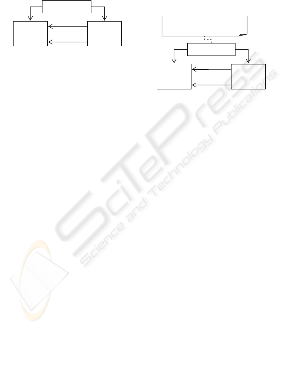
To model the same kind of structure using OO
modelling, Class Diagrams, we would typically
define classes DirectedGraph, Node and Edge, and
then define associations between the classes that
indicate the relationships between nodes and edges
and the graph as a whole. This is illustrated in the
simplest form by Figure 1.
Figure 1: Typical OO Model of a Directed Graph.
Interestingly, even with this simple graph
structure, there are significant differences between
the mathematical and OO forms of model. If we
interpret each class in the typical OO programming
context, then there is an implicit property of each
class/object (equitable to the memory location of the
object representation) that defines the objects
identity. In the case of the Node class, a ‘label’
property has been given, but there is nothing in the
model that specifies that this property defines the
identity of Node objects.
In the mathematics, the identity of the nodes (N)
are made explicit by defining a node as an integer;
however, neither graph (G) nor edge (E) have an
explicit identity other than the implicit identity of
the tuple and set on which they are defined.
With respect to the OO model the question arises
as to whether two edge objects that refer to the same
two nodes are a single edge or two separate edges. In
the mathematics, the definitions of identity for tuples
clearly indicates that, not only are two pairs of the
same two nodes, the same edge, but that a graph
cannot have two edges between the same two nodes
(something can only appear once in a set.)
Another difference is that the mathematical
model specifies that the two ends of an edge are
members of the set of nodes. The OO model does
not make this restriction; the edges in this model
may be node objects that do not appear in the set of
nodes for the graph.
Table 2: Mathematical version of OO Model of a Directed
Graph.
Graph = (id, nodes, edges )
id ∈ Ζ
nodes ⊆ { (id, label) | id, label ∈ Ζ }
edges ⊆ { (id, n1, n2) | id ∈ Ζ, n1 ∈ Node, n2
∈ Node }
So is our mathematical model wrong, or is it the
OO model that is incorrect? Neither, they just
happen to model two different structures. A
mathematical model of the same structure as defined
by the OO model of Figure 1 is shown in Table 2.
In this structure we have explicit modelled the
‘memory location’ identity as an Integer, and we
start
[1]
DirectedGraph
Integer
[*] nodes
Edge
[*] edges
finish
[1]
MATHS VS (META)MODELLING - Are we Reinventing the Wheel?
315
define edges to reference two elements of the set of
all Node objects as opposed to two elements from
the set of nodes in the graph.
Figure 2: Another OO Model of a Directed Graph.
An OO model that provides a slightly better
match to the original mathematical definition from
Table 1 is illustrated in Figure 2.
This second OO model directly models the nodes
of a graph as a set of integers. However, using this
simple class diagram language, there is no way to
provide a completely equivalent model:
1. We have no means to define the identity of
classes/objects. In the case of an Integer, one
has to assume that its value is its identity, but
for the Graph and Edge classes, there is the
implicit notion of ‘memory location’ identity
which we have no means to override. Ideally we
would define the identity of an edge as being
equivalent to the set of its ends.
2. We also have no way to define that the ends of
an edge must be a subset of the nodes in the
graph.
To enable the precision of specification easily
achieved with the mathematical approach, we must
add a means for defining/overriding the identity of
objects and a way to add constraints.
Both of these things have been addressed (to an
extent) by the designers of the UML. Additional
constraints can be added to a model using the OCL,
and there is a basic mechanism for defining that
certain properties of a class define its identity
1
.
Using this extended language of class diagrams we
can now give an equivalent structural specification
of our original mathematical definition of a graph,
shown in Figure 3.
This OO model of a directed graph is a much
more precise specification. However, even though it
does match the mathematical definition, it seems
somewhat clumsy with the need for the additional
constraint. Also the use of the Integer class directly
for modelling nodes does not seem quite like the OO
approach to modelling.
If we make use of bi-directional associations and
extend the use the UML 2.0 notion of subsetting
2
we
can construct a new model as illustrated in Figure 4.
Figure 3: OO version of Mathematical model of a Directed
Graph.
In this model:
• Node objects are identified by their label – the
label property is marked as an identifying
property.
• Edges are identified by the nodes they connect –
the start and finish properties are marked as
identifying
• The ends of an edge are constrained to be nodes
in the same graph – the start and finish properties
are constrained to be subsets of the nodes in the
graph.
In addition the model provides bi-directional
navigation between Node objects and the edges that
connect them, which although non-essential is likely
to be very useful.
This final OO model of directed graphs is, in our
opinion, by far the most effective model. The initial
OO model, although simple and intuitive, was not
precisely correct. By looking at the traditional
mathematical model it becomes apparent that the
notion if identity is important, as is a mechanism for
constraining the ends of edge objects to be part of
the same graph as the edge itself.
There are mechanisms designed into the UML
language of class diagrams that nearly enable us to
model as precisely as the traditional maths, however
these notions are not quite sufficient, and more
importantly are seen as ‘additions’ to an OO model
rather than primary things to consider aspects of the
semantic behaviour implied by those structures.
This example has looked solely at models of
structure (a graph has no behaviour). In the next two
sections we look at modelling more complex
structures (languages) and at specifying some.
start
[1]
DirectedGraph
Intege
r
[
*
]
nodes
Edge
finish
[1]
[
*
]
ed
g
es
DirectedGraph
Intege
r
[*] nodes
nodes->includesAll(
edges.start.union(edges.finish) )
start {id}
[1]
Edge
finish {id}
[1]
[*] edges
1
We extend the official UML facility slightly, allowing us to
mark multiple properties as jointly defining an object’s identity
and allowing those properties to be association ends as well as
attributes.
2
Officially, association ends should only subset othe
r
associations ends with the same source object.
ICSOFT 2008 - International Conference on Software and Data Technologies
316

Figure 4: Better OO model of Directed Graph.
3 PETRI-NETS
A more interesting example than simple graphs is
that of Petri-nets (Murata, 1989). A Petri-net is
directed, weighted, bipartite graph, together with an
initial state called the initial marking, M
0
. Petri-net
graphs consist of two types of nodes, called places
and transitions, whereas edges are either from places
to transitions or from transitions to places. If there is
an arc from a place p to a transition t, we say p is an
input place of t, and t is an output transition of p.
Places are depicted as circles and transitions as
rectangles. Arcs are labelled with positive integers,
called weight. A marking of a Petri-net assigns a
non-negative number, known as the number of
tokens, to each place. A marking M is in effect an
integer valued vector of dimension m, where m is
the number of places. Hence, each coordinate of M
denotes the number of the number of tokens in the
corresponding place. Table 3 presents a formal
definition of a Petri-net, taken from (Murata, 1989).
Table 3: Mathematical definition of a Petrinet.
PN = (P, T, F, W, M
0
)
P = {p
1
,p
2
…p
m
} is finite set of Places
T = {t
1
,t
2
,…t
n
} is a finite set of transitions
F ⊆ (P×T) ∪ (T×P) is a set of arcs
W: F → {1,2,3,…} is a weighting function
M: P → {0,1,2, …} is a marking.
M
0
is the initial marking.
An OO model would be more likely to define
Petri-nets as illustrated in Figure 5. A Petri-net being
a containing class for Place, Transition and Arc
objects. There being two kinds of Arc, Place-
>Transition Arcs and Transition->Place Arcs. The
additional definition of Markings is as
shown in
Figure 6.
As with the directed graph definition, it is
necessary to augment the class diagram with
additional constraints, which in the mathematical
model are unnecessary. In this case the constraints
ensure that the ends of the arcs are members of the
sets of places and transitions in the petri-net.
The other major difference between these two
specifications is the explicit definition of types for
Arcs in the OO model, which in the maths
specification are defined jointly as the union of
tuples (place,transition) and (transition,place).
3.1 Semantics
With the definition of a language, in this case Petri-
nets, we can go a step further than we did with the
graph model. The runtime semantics of Petri nets are
defined using the traditional mathematical
specification approach. In the OO modelling world
this is less often defined; however, it is perfectly
feasible to do so, using the standard UML/OCL
language facilities.
Semantics of a Petri net can be interpreted as a
labelled transition system, in which each state of the
Petri is a marking of the Petri net. Change of one
state of a Petri net to another state is governed by the
firing rules:
1) A transition t is called enabled if for each of its
input places p has at least w(p,t) tokens, where
w(p,t) is the weight of the arc from p to t.
2) An enabled transition t may fire, in which case
w(p , t) tokens are removed from each input
place p of the transition t and w(t , p’) tokens
are added to the each output place p’ of t.
Firing of an enabled transition t under a marking
M resulting in new marking M’ is denoted by M [t>
M’. A Reachable marking (state) of a Petri net is a
marking M
k
such that there are marking M
1
, M
2
, …,
M
K+1
and transition t
1
, t
2
, …, t
k
satisfying the
following
M
0
[t
1
> M
1
[t
2
> M
2
[t
3
> … [t
K+1
> M
K+1
[t
K
> M
K
In this case the sequence of transitions t
1
t
2
…t
k
is
called a run.
start {subsets graph.nodes }
[1]
DirectedGraph
Node Edge
[*] nodes
label : Integer {id}
[*] edges
finish {subsets graph.nodes }
[1]
graph
[1]
Graph
[1]
Outgoing
[*]
Incoming
[*]
MATHS VS (META)MODELLING - Are we Reinventing the Wheel?
317
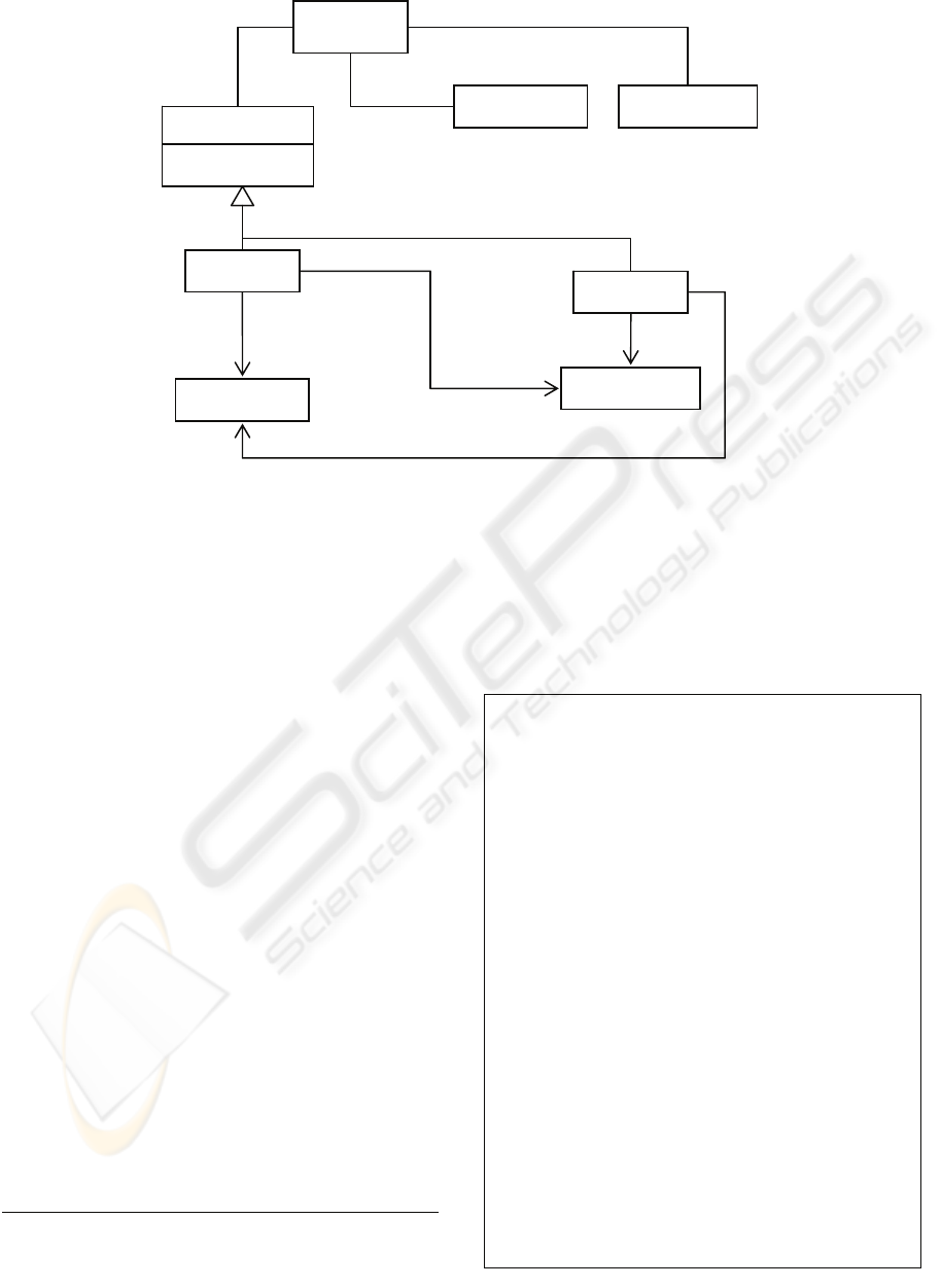
Figure 5: OO (Meta) Model of Petri-Nets.
To add this semantics to the OO model of Petri-
nets we can define operations on the classes that
provide the firing behaviour, the body of the
operations can be given using OCL expressions
3
.
To facilitate more concise OCL expressions, we
would also adapt the OO model making more use of
bi-directional associations.
Figure 6: OO (Meta) Model of PetrNets.
shows an evolved specification of the model
from Figure 5, including the specification of
Markings and use of bi-directional associations.
(The constraints have been left out for clarity.)
Given this specification of the model of a Petri-
net, we can define the behaviour of the operations as
shown in Table 4.
Using these definitions we could define further
operations that would simulate execution of the
Petri-net, or search the reachable Markings. One
could even go so far as to build various model-
checking operations.
It can be seen from these specifications that a
graphical OO definition of the language can be as
precise as the more traditional definition. It is also
possible, using the OO approach, to define
operations that aid the semantic interpretation of the
language.
One distinct advantage of the OO definition, over
the traditional, is that the MDD and code generation
techniques (Akehurst, 2007, Budinsky, 2003) enable
this definition of the language to be used to
automatically produce an executable version of the
model that can be used as a first cut evaluator for the
language.
Table 4: Definitions for Petri-net behaviour.
context
Transition::isEnabled(current:Marking) :
Boolean
body: incoming->forAll( arc |
let mark = current.mark-
>any(m|m.place=arc.src) in
mark.tokens >= arc.weight
)
context Transition::fire(current:Marking)
: Marking
body: let
unaffected = current.mark->reject( m |
incoming.src-
>union(outgoing.dst)->includes(m.place) ),
lost = incoming.src->collect( arc |
let mark = current.mark-
>any(m|m.place=arc.src) in
Mark { place = arc.src,
tokens =
mark.tokens-arc.weight } ),
gained = outgoing.dst->collect( arc |
let mark = current.mark-
>any(m|m.place=arc.src) in
Mark { place = arc.dst,
tokens =
mark.tokens+arc.weight } ),
in
Marking {
mark =
unaffected.union(lost).union(gained)
}
PetriNe
t
Place Transition
src [1] {subsets net.places}
[*]
places
[
*
]
transitions
PTArc
TPArc
dst [1]
{subsets net.transitions}
A
rc
[
*
]
arcs
Transition
Place
{subsets net.transitions} [1] src
dst [1] {subsets net.places}
weight : Integer
ne
t
[1]
ne
t
[1]
net [1]
3
We find it necessary to use an extension of OCL that allows us
to create instances of user model objects. Creation of such objects
is similar to the creation of tuples in standard OCL.
ICSOFT 2008 - International Conference on Software and Data Technologies
318
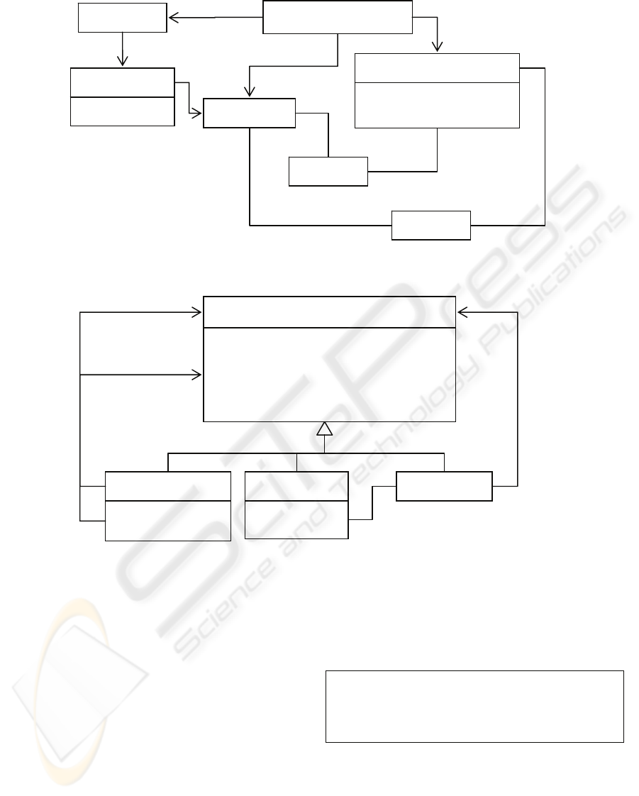
Figure 6: OO (Meta) Model of PetrNets.
Figure 7: OO (Meta) Model of Lambda Calculus.
Another, more subjective, observation is that the
graphical specification of the concepts of Place,
Transition and Arcs conveys more information to the
reader about the structure of expressions in the
language than does the text based more traditional
specification.
4 UNTYPED LAMBDA
CALCULUS
The third example we will look at is one of the
fundamental languages of computer science -
lambda calculus. The definition of this language
(taken from (Thompson, 1991)) is given as a
grammar shown in Table 5. The definition of this
language differs from the previous two examples, in
that the language definition is given using its syntax,
in BNF, rather than being a set theory based
definition.
Table 5: Grammar for Lambda Calculus.
expr = ID
| 'λ' ID '.' expr
| expr expr
;
Further definition of the language is then given
using text definitions and illustrated by examples.
The semantic of the language are given by defining
the notions of substitution (α-conversion) and β-
reduction. These definitions are shown in Table 6.
Using OO modelling techniques we can provide
equivalent definitions, but using a metamodel of the
Mark
tokens : Integer
PetriNet
Place
Transition
incoming
[*]
[*] places
[*] transitions
PTArc
TPArc
dst
dst
src
Marking
initialMarking
[*]
[*]
outgoi
ng
[*] outgoing
incoming
[*]
src
fire(c:Marking):Marking
isEnabled(c:Marking):Boolean
name : String{id}
Expr
Variable Abstraction
expr [1]
param [1]
Application
hasFree(v:Variable) : Boolean
substitute(v:Variable,w:Expr) : Expr
reduce() : Expr
createVariable() : Variable
[0..1]
arg [1]
func [1]
MATHS VS (META)MODELLING - Are we Reinventing the Wheel?
319

lambda calculus concepts, and OCL to define the
substitution and reduction functions. A mapping can
be given from a concrete syntax to the metamodel,
but the details of this are not in the scope of this
paper. A metamodel for the Lambda calculus is
given in Figure 7. It shows an abstract Expr type
which is realised by the three kinds of expression
that can be formed, a function Application, a
Variable, and a function Abstraction.
Table 6: Definitions of substitution and reduction.
The substitution of f for the free occurrences of
x in e, written e[f/x] is defined thus.
• x[f/x] ↑
df
f and for a variable y ⎣ x, y[f/x] ↑
df
y
• For applications, we substitute the two parts:
(e1 e2)[t/x] ↑
df
(e1[t/x] e2[t/x])
• If e ↑ λx.g then e[f/x] ↑
df
e. If y is a variable
distinct from x, and e ↑ λy.g then
- if y does not appear free in f,
e[f/x] ↑
df
λy.g[f/x].
- if y does appear free in f, e[f/x]
↑
df
λz.(g[z/y][f/x])
• In general, it is easy to see that if x is not
free in e then e[f/x] is e.
The rule of β-reduction states that, for all x, e
and f, we can reduce a function application by
substituting the argument for the bound variable
• (λx.e) f φ
β
e[f/x]
And if e φ
β
e' then
• (f e) φ
β
(f e')
• (e g) φ
β
(e' g)
• λy.e φ
β
λy.e'
Based on this metamodel, the notion of
substitution can be defined as an operation that
returns a new Expr. The behaviour of such an
operation needs to be defined on each kind of
expression and these definitions are given in Table
7.
Reduction is the expansion of a function
application, substituting the argument for the
function parameter. This also can be defined by
operations on the Expr sub-classes, as shown in
Table 8.Further concepts such as equivalence,
normalization or η-reduction can be defined as
additional operations that make use of the reduction
and substitution functions. It is interesting to note
that the addition of a transitive closure operation
within OCL would ease the definition of some of
these additional operations.
It is of course a very subjective issue as to
whether the traditional BNF based specification of
this language is better or worse than the OO version.
Your preference as a reader of the definition
probably depends largely on your background and
previous experience of specifications. However, as
is the case with the Petri-net example, this definition
can be used to generate an executable model of the
language. It is also interesting to see the difference
between basing the language definition on the syntax
or the concepts. The traditional approach defines the
syntax of the language and uses this on which to
base the definition of the semantic functions. In
contrast the metamodel defines only the concepts of
the language (potentially enabling multiple
syntaxes), but still provides precise definition of the
semantic substitute and reduction functions.
Table 7: OCL Definitions for substitution (α-conversion).
context Variable::hasFree(v:Variable) :
Boolean
body: self==v
context Application::hasFree(v:Variable)
: Boolean
body: func.hasFree(v) and arg.hasFree(v)
context Abstraction::hasFree(v:Variable)
: Boolean
body: param <> v and expr.isFree(v)
context Variable::substitute(v:Variable,
w:Expr) : Expr
body: if self==v then w else self endif
context
Application::substitute(v:Variable,
w:Expr) : Expr
body: Application { func =
func.substitute(v,w),
arg =
arg.substitute(v,w) }
context
Abstraction::substitute(v:Variable,
w:Expr) : Expr
body: if w.hasFree(param) then
let z = createVariable() in
Abstraction { param = z,
expr =
expr.substitute(param,z).substitute(v,w)
}
else
Abstraction { param = param,
expr =
expr.substitute(v,w) }
endif
5 CONCLUSIONS
The paper has employed Object-Oriented graphical
specification techniques to model three separate
well-known languages or data structures. These
ICSOFT 2008 - International Conference on Software and Data Technologies
320

Table 8: OCL Definition for β-reduction.
. context Variable::reduce() : Expr
body: self
context Abstraction::reduce() : Expr
body: self
context Application::reduce() : Expr
body: if func.oclIsKindOf(Abstraction) then
func.substitute(func.oclAsType(Abstraction).param,arg)
else
self
endif
examples are initially specified using traditional
mathematical techniques and it has been shown that
these may equally well be expressed using the O-O
graphical methods. Further, the paper has sought to
demonstrate the increased ease of comprehension of
the O-O graphical techniques by contrasting the two
alternative specification techniques.
The major observations may be summarised as
follows:-.
• It is surprising that OO modelling seems to have
forgotten the importance of identity. Notions of
identity, naturally assumed in mathematical
specifications are not the same as the default
notions in OO models. Relational modelling,
itself an ancestor of UML, in contrast, makes this
importance clear via primary keys.
• An important advantage of the OO graphical
approach may be deduced by the assumption that
mental pictures will be created by a reader when
digesting a specification. When reading
mathematical or text based specifications, the
mental picture is constructed by the reader. In
contrast, by explicitly giving the picture as part
of the specification (class diagram) this helps the
specification writer ensure that his own mental
picture is better communicated to the reader.
This significantly improves the ability to
mentally communicate and/or interpret the
abstract concepts involved.
• By modelling languages using class diagrams we
gain the added advantage of being able to
automatically generate tool support for the newly
created language. The Model Driven
Development (MDD) and code generation
techniques developed for aiding rapid
development of general software systems can be
readily employed as part of the Domain Specific
Languages (DSL) or grammarware engineering
(Klint, 2003) discipline supporting the rapid
development of tools to support new or new
versions of a language. Such support is not
generally available if given a specification in a
traditional mathematical formalism, other than
perhaps that given by compiler compilers.
• OO Modelling gives a more complex set of basic
concepts for producing models, whereas
mathematics uses a much simpler set. For
example, notions of extensibility in OO
techniques are not generally primitive concepts
in traditional specification techniques. Due to the
simplicity of the primitives used within the
mathematical models, the expressions tend to be
more precise and unambiguous.
• Ironically, the ease of comprehension possessed
by OO graphical techniques means that a human
reader is likely to infer fewer ambiguities in this
presentational style than would be the case for
the mathematical techniques, even though the
mathematical techniques will actually contain
fewer ambiguities.
Metamodelling is a practical engineering
approach to modelling a language whose primary
goal is to aid the designer in producing a working
solution to a problem. In contrast, the mathematical
approach is primarily driven by the need for
precision and accuracy rather than practical utility.
Although metamodelling can be as precise as a
mathematical approach, some of the underlying
concepts do not encourage this precision.
So, is metamodelling reinventing the wheel?
Yes, but the wheel is a different colour! Specifically,
many of the same concepts are available but their
utility is improved by the improved accessibility of
the concepts concerned. I.e. this colour of wheel is
easier on the eye!
MATHS VS (META)MODELLING - Are we Reinventing the Wheel?
321

ACKNOWLEDGEMENTS
This research is supported at the Department of
Electronics at University of Kent and at
LIFL/INRIA Futurs at the University of Lille though
the European Union ERDF Interreg IIIA initiative
under the MODEASY grant.
REFERENCES
OMG, "UML 2.0 Infrastructure Specification," Object
Management Group ptc/03-09-15, September 2003
2003.
OMG, "UML 2.0 Superstructure Specification," Object
Management Group ptc/03-08-02, August 2003 2003.
C. Atkinson and T. Kuhne, "Model-driven development: a
metamodeling foundation," Software, IEEE, vol. 20,
pp. 36-41, 2003.
A. G. Kleppe, J. B. Warmer, W. Bast, and A. Watson,
MDA Explained: The Model Driven Architecture:
Practice and Promise: Addison-Wesley Professional,
2003.
B. Selic, "The pragmatics of model-driven development,"
Software, IEEE, vol. 20, pp. 19-25, 2003.
K. Chen, J. Sztipanovits, and S. Neema, "Toward a
semantic anchoring infrastructure for domain-specific
modeling languages," Proceedings of the 5th ACM
international conference on Embedded software, pp.
35-43, 2005.
J. Greenfield and K. Short, Software factories: assembling
applications with patterns, models, frameworks and
tools: ACM Press New York, NY, USA, 2003.
A. van Deursen, P. Klint, and J. Visser, "Domain-specific
languages: an annotated bibliography," ACM
SIGPLAN Notices, vol. 35, pp. 26-36, 2000.
M. Vokac and J. M. Glattetre, "Using a domain-specific
language and custom tools to model a multi-tier
service-oriented application-: Experiences and
challenges," Lecture notes in computer science, pp.
492-506.
D. Wile, "Supporting the DSL Spectrum," Journal of
Computing and Information Technology, vol. 9, pp.
263-287, 2001.
M. Alanen and I. Porres, A Relation Between Context-free
Grammars and Meta Object Facility Metamodels:
Turku Centre for Computer Science, 2004.
M. Wimmer and G. Kramler, "Bridging grammarware and
modelware," Satellite Events at the MoDELS 2005
Conference: MoDELS, pp. 159–168, 2005.
V. Stoltenberg-Hansen, I. Lindström, and E. R. Griffor,
Mathematical theory of domains: Cambridge
University Press New York, NY, USA, 1994.
J. E. Stoy, Denotational Semantics: The Scott-Strachey
Approach to Programming Language Theory: MIT
Press Cambridge, MA, USA, 1977.
F. K. Hanna and N. Daeche, "Dependent Types and
Formal Synthesis," Philosophical Transactions:
Physical Sciences and Engineering, vol. 339, pp. 121-
135, 1992.
F. K. Hanna, N. Daeche, and G. Howells, "Implementation
of the Veritas Design Logic," Proc. of the
International Conference on Theorem Provers in
Circuit Design: Theory, Practice and Experience, pp.
77-94, 1992.
F. K. Hanna, N. Daeche, and M. Longley, "Specification
and verification using dependent types," IEEE
Transactions on Software Engineering, vol. 16, pp.
949-964, 1990.
A. Cohn, "The notion of proof in hardware verification,"
Journal of Automated Reasoning, vol. 5, pp. 127-139,
1989.
T. Murata, "Petri Nets: P
roperties, Analysis and
Applications," Proceedings of the IEEE, vol. 77, pp.
541-580, 1989.
D. Akehurst, G. Howells, and K. McDonald-Maier,
"Implementing associations: UML 2.0 to Java 5,"
Software and Systems Modeling, vol. 6, pp. 3-35,
2007.
F. Budinsky, Eclipse Modeling Framework: A Developer's
Guide: Addison-Wesley, 2003.
S. Thompson, Type theory and functional programming:
Addison-Wesley Wokingham, England, 1991.
P. Klint, R. Lämmel, and C. Verhoef, "Toward an
engineering discipline for grammarware," ACM
Transactions on Software Engineering and
Methodology (TOSEM), vol. 14, pp. 331-380, 2005.
ICSOFT 2008 - International Conference on Software and Data Technologies
322
