
A UML-BASED VARIABILITY SPECIFICATION FOR PRODUCT
LINE ARCHITECTURE VIEWS
Liliana Dobrica
Faculty of Automation and Computers, University Politehnica of Bucharest
Spl. Independentei 313, Bucharest, Romania
Eila Niemela
VTT Technical Research Center of Finland, Oulu, Finland
Keywords: Software architecture, service, UML, product line, variability.
Abstract: In this paper we present a rigorous and practical notation for specifying variability in product line
architecture views expressed in the Unified Modeling Language (UML). The notation has been used for the
explicit representation of variations and their locations in software product line architectures based on a
design method already established. The improvement consists in a service orientation of architectural
models. The benefit of a more familiar and widely used notation facilitates a broader understanding of the
architecture and enables more extensive tool support for manipulating it. The specification notation paves
the way for the development of tools.
1 INTRODUCTION
Product line (PL) software development requires a
systematic approach from such multiple perspectives
as business, organizational, architecture and process.
In the PL context, the architecture is used to build a
variety of different products. For several years the
focus of our research has been product line
architecture (PLA) design and analysis. One of our
goals was to define a Quality-driven Architecture
Design and quality Analysis (QADA) method
(Matinlassi et al., 2002) for modeling middleware
services architectures. An important issue in our
research was to explicitly represent variation and
indicate locations for which change is allowed. In
this way, the diagrammatic description of the PLA
defined by using our method helps in instantiating
PLA for a particular product or in its evolution for
future use. From the PLA documented
diagrammatically, it is easy to detect what kind of
modifications, omissions and extensions are
permitted, expected or required.
The QADA
SM
method was described by defining
and using a framework that consisted of the
following ingredients: (1) an underlying model,
referring to the kinds of constructs represented,
manipulated and analyzed by the model; (2) a
language, which is a concrete means of describing
the constructs, considering possible diagrammatic
notations; (3) defined steps, and the ordering of
these steps; (4) guidance for applying the method;
and (5) tools that help in carrying out the method. In
order to achieve an optimal method for a certain
development effort, these ingredients can be defined
or selected more properly. Some of these ingredients
may already be available (e.g. from the literature,
from tool vendors, etc.), whereas others may have to
be specially developed, configured or extended.
The work in this paper puts in practice this idea
of method improvement with the purpose of defining
the UML extensions for the management of
variability in space in the software architectures of
PLs. The improvement consists in a service
orientation of architectural components. The
extensions are described through the viewpoints
defined by the QADA
SM
method. The method will
benefit a more familiar and widely used notation,
therefore facilitating a broader understanding of the
architecture and enabling more extensive tool
support for manipulating it. Also the service oriented
approach of QADA improvement is more practical,
easier to follow and benefits of advantages provided
by service engineering. Our goal is to describe
modeling constructs that manage variability and
234
Dobrica L. and Niemela E. (2008).
A UML-BASED VARIABILITY SPECIFICATION FOR PRODUCT LINE ARCHITECTURE VIEWS.
In Proceedings of the Third International Conference on Software and Data Technologies - SE/GSDCA/MUSE, pages 234-239
DOI: 10.5220/0001899202340239
Copyright
c
SciTePress

represent a part of a profile of the extended or
applied UML concepts intended primarily for use in
modeling the PLAs. These new constructs have to be
used in combination with the other UML modeling
concepts and diagrams to provide a comprehensive
modeling tool set.
The beginning of this paper is a brief description
of the viewpoints of the QADA
SM
method, with the
focus on modeling elements and relationships with
UML extension mechanisms and notation. The next
section examines some of the structural and behavior
constructs that model variability, trying to interpret
them based on UML concepts. UML extension
mechanisms are used if a refinement of the UML
metamodel is necessary. The final result of our
research is the definition of a UML profile for
designing software architectures based on the
QADA
SM
method. We think that standardization of
the UML profile defined in our study will be of
benefit to the software architecture developer
community, especially for software PLs where a
systematic approach is mostly required.
2 MODELING CONSTRUCTS
The modeling constructs used by the QADA
SM
method for representing software architectures for
PL development are partitioned into four groups:
structural view, behavioral view, deployment view
and development view. Variation in space is an
integral part of the first three views. The
development view includes technologies and work
allocation. There are also two levels of abstraction to
be considered in PLA descriptions: the conceptual
level and the concrete level. Entities of each view
are defined in detail in (Purhonen et al., 2004).
Conceptual Views
Structural Behavior Dep loy men t
Elem ents
MultipleDomains,
Domain, Service
Relationships
Passes-data -to - «data»
Passes-contro l-to - «control »
Uses - «uses»
Elem ents
Service(Instance)
Relationships
Ordered-
sequence-
of actions
Elements
Deployment No de
Unit of deplyoment
Relationships
Is -a lloca ted-to
Figure 1: Entities of the conceptual view.
Extended QADA defines a Service as the behaviour
of producing some outputs that other services want.
Services are identified based on a specific feature
model (Dobrica and Niemela, 2008). A Domain
consists of services that are related based on certain
factors, such as hardware or architect’s experience.
MultipleDomains is required to design architectural
views in the context of system-of-systems, where
systems of yesterday become components of today.
Figure 1 presents the entities of three major
conceptual views that embody variation in space.
Variation in time is managed through the conceptual
and concrete development views, but that is outside
the scope of this paper. On a concrete level there are
other architectural elements (i.e. capsules, ports,
state diagrams, deployment diagrams, etc.) and
relationships between them in each of the views.
To address UML extensions in accordance with
the QADA
SM
method we have defined and applied a
framework, accompanied by a set of activities and
techniques, for identifying differences between the
UML standard and the QADA
SM
viewpoint
descriptions. The framework is based on the
following activities: (1) Mapping: Identifies what
information is overlapping between the existing
QADA
SM
language and UML; (2) Differentiation:
Identify differences between the UML standard
model elements and those defined by QADA
SM
; (3)
Transformation: By using UML extension
mechanisms or other techniques we try to integrate
the UML standard with the new required elements.
UML supports the refinement of its specifications
through three built-in extension mechanisms (OMG
UML, 2003): (1) constraints that place semantic
restrictions on particular design elements and are
defined by using Object Constraint Language
(OCL); (2) tagged values that allow new attributes
to be added to particular elements of the model, and
(3) stereotypes that allow groups of constraints and
tagged values to be given descriptive names and
applied to other model elements. The semantic effect
of stereotypes is as if the constraints and tagged
values were applied directly to those elements.
These mechanisms are used to define extended
metaclasses in a package that is called UML profile.
Tabular forms for specifying the new extensions
have been organized (Figure 2). For stereotypes, the
tables identify stereotype name, the base class of the
stereotype that matches a class or subclass in the
UML metamodel, the direct parent of the stereotype
being defined (NA if none exists), an informal
description with possible explanatory comments and
constraints associated with the stereotype. Finally,
the notation of the stereotype is specified. For
example, based on QADA
SM
, the conceptual
structural view is used to record conceptual
structural components, conceptual structural
A UML-BASED VARIABILITY SPECIFICATION FOR PRODUCT LINE ARCHITECTURE VIEWS
235

relationships between components and the
responsibilities these elements have in the system.
Specifically in QADA
SM
, the constructs for
modeling this view are summarized in Figure 1.
Tabular form of a Stereotype
definition
• Stereotype: Service
• Base Class: Subsystem
• Parent: Architectural element
• Description: ...
• Constraints: None or
self.isMandatory=true
• Tags: None
Notation: A UML package
stereotyped as «service»
Tabular form of a Constraint definition
• Constraint: isMandatory
• Stereotype: Service
• Type: UML::Datatypes::Boolean
• Description: Indicates that the
Service is Mandatory
Tabular form of a Tag definition
• Tag: isDynamic
• Stereotype: Capsule
• Type: UML::Datatypes::Boolean
• Description: Identifies if the
associated capsule class may be
created and destroyed dynamically.
Figure 2: Stereotype, constraint and tag definitions.
Typically, UML provides class diagrams for
capturing the logical structure of systems. Class
diagrams encapsulate universal relationships among
classes – those relationships that exist in all contexts.
Components of a conceptual structural view are
mapped onto the Subsystem UML concept. We
identified a hierarchical description of components
that introduces differences between them and
requires transformations using new stereotypes. The
stereotypes enhance additional conceptual-specific
semantics onto the various aspects that are
associated with the UML-based classes. We
proceeded with mapping elements and identifying
the new required stereotypes.
«stereotype»
«stereotype»
Service
«stereotype»
MultipleDomains
«stereotype»
«stereotype»
Domain
«metaclass»
Subsystem
«metaclass»
GeneralizableElement
«metaclass»
Classifier
«stereotype»
ArchitecturalElement
Figure 3: Stereotype in a graphical representation.
A graphical equivalent of the stereotype declarations
previously described for tabular form is presented in
Figure 3. This shows the relationships among UML
metaclasses and the new stereotypes they represent
in architectural views. Generalization and predefined
«stereotype» dependency are included here.
3 MODELING VIEWS
An important aspect of PLAs is variation among
products. UML provide the means to use specific
variation mechanisms (Webber and Gomaa, 2002)
(Jacobson et al., 1997) to describe hierarchical
systems (ways to decompose systems into smaller
subsystems). However, the UML does not support a
description of variation, as QADA
SM
requires.
3.1 Conceptual Structural View
We consider variation in the conceptual structural
view to be divided into internal variation (within
Service components) and structural variation
(between Service/Domain components). To enable
variation, we separate components and
configurations from each other. Flexible
representations are needed to instantiate components
and bind them into configurations during product
derivation.
3.1.1 Structural Variation
The structural conceptual view has to offer the
possibility of preventing automatic selection of all
Service components included in a Domain during
product derivation. Variability is included in this
view by using specific stereotypes for the
architectural elements (Figure 4).
«mandatoryService»
Service1
(from Domain1)
«optionalService»
Service2
(from Domain1)
«alternativeService»
Service4
(from Domain1)
B
«alternativeService»
Service3
(from Domain1)
A
«optionalAlternativeService»
Service5
(from Domain1)
A
«mandatoryService»
Service6
(from Domain1)
«control(opt)»
«control(alt)»
«control»
«data(optAlt)»
«uses(alt)»
«mandatoryDomain»
Domain1
Figure 4: Variation in the conceptual structural view.
Thus we consider that a Service could be further
stereotyped in: «mandatoryService» «alternative
Service»; «optionalAlternativeService» «optional
Service». We recommend that in case of
«alternative» or «optionalAlternative» variability of
a Service, the inclusion of a letter “A” or “B”, etc.,
at the bottom of the UML package symbol. The
letter anticipates the product identifier that requires
that architectural variation.
ICSOFT 2008 - International Conference on Software and Data Technologies
236

Variation points included in the conceptual
structural view are shown in Figure 4. Domain1 is a
«mandatoryDomain» that consists of
«mandatoryService» components (Service1 and
Service6), «optionalService» component (Service2),
«alternativeService» (Service3 of product A and
Service4 of product B) «optionalAlternativeService»
(Service5 of product A). In this way, variation points
identify locations at which the variation will occur.
Some of the constraints that govern variability
cannot be expressed by the UML metamodel. They
concern the following: (a) If a «mandatory Domain»
only consists of «optionalService» components, at
least one of them must be selected during the
derivation process; otherwise, a «Domain» that only
consists of «optionalService» components must be
an «optionalDomain». (b) Two «alternativeService»
components of different products are exclusive,
meaning that only one can be selected for a product.
The product is specified at the bottom of the
notation. (c) There should be no relationships
between alternative or optionalAlternative
components; they belong to different products. The
relationships are appropriately stereotyped (Table 1).
Table 1: Stereotypes of relationships for variability.
Stereotype Represents
«control»
«data»
«uses»
Control/ Data/ Uses association
between two
mandatory services
(UML).
«control (opt)»
«data (opt)»
«uses (opt)»
Control/ Data/ Uses association
between two services (UML). At
least one of them is an
optional
stereotype.
«control (optAlt)»
«data (optAlt)»
«uses (optAlt)»
Control/ Data/ Uses association
between two services (UML). At
least one of them is an
optionalAlternative stereotype.
3.1.2 Internal Variation
We define internal variation only for mandatory
Service components. A Service component is on the
lowest hierarchical level and may perform a required
functionality that may vary depending on products.
«mandatoryService»
ServiceName
vp <<m|o><VariationName>>|
<<a|oa><VariationName><ProductId>>
Figure 5: Internal variation of a mandatoryService.
The internal variation of Service components is
designated by a ● symbol (Figure 5). Although the
symbol is not included in the UML standard,
(Jacobson et al., 1997) and later (Webber and
Gomaa, 2002) introduced the ● symbol for variation
points. The UML tag syntax
vp <<m|o><VariationName>> |
<<a|oa><VariationName><ProductId>>
shows the reuser the parts of an internal variation so
that the reuser can build a product. Mandatory (m)
or optional (o) functionality (VariationName) of a
Service component is specified in the tag syntax. In
the case of alternative (a) or optionalAlternative (oa)
the product identifier (ProductId) is also specified.
3.2 Conceptual Behavior View
The conceptual behavior view may be mapped
directly onto a hierarchy of UML collaboration
diagrams. The elements of this view are
roles/instances of the Service stereotypes defined in
the conceptual structural view.
Variable parts of a collaboration or interaction
diagram can be represented with dashed lines.
Optional messages between ServiceComponents use
dashed lines with solid arrowheads (Figure 6).
1: mandatoryMessage
:OptionalServiceComponen
t
1
3: optionalMessage 2.2: optionalMessage
:MandatoryServiceComponent2
:MandatoryServiceComponent3
2.1: optionalMessage
Figure 6: Optional interactions.
:OptionalServiceComponent
3: optio nalMessage
:MandatoryServiceComponent
4: alternativeMessage (P_Id)
:AlternativeServiceComponent (P_Id)
:OptionalAlternativeServiceComponent (P_Id)
5: optAltMessage (P_Id)
1: m and atorylMessag e
Figure 7: Variability in the conceptual behavior view.
Collaboration diagrams describe each operation that
is part of the specification requirements. Similar to
the conceptual structural view, alternative and
optionalAlternative Service instances may be
represented in this view. An identifier of the specific
A UML-BASED VARIABILITY SPECIFICATION FOR PRODUCT LINE ARCHITECTURE VIEWS
237
product that requires a particular interaction should
be introduced and represented in the diagram. The
notation used in collaboration diagrams for
variability representation is shown in Figure 7. A
dashed line is the notation for optional message, a
dotted line indicates alternative message and a dash-
dotted line is used for optional alternative.
3.3 Conceptual Deployment View
In UML a deployment diagram shows the structure
of the nodes on which the components are deployed.
The concepts related to a deployment diagram are
Node and Component. DeploymentNode in
QADA
SM
is a UML Node that represents a
processing platform for various services. The
notation used for DeploymentNode is a Node
stereotyped as «DeploymentNode». UML notation
for Node (a 3-dimensional view of a cube) is
appropriate for this architectural element.
A DeploymentUnit is composed of one or more
conceptual service components. Clustering is done
according to a mutual requirement relationship
between services. It cannot be split or deployed on
more than one node. The stereotype,
«deploymentUnit» is a specialization of the
ArchitecturalElement stereotype and applies only to
Subsystem, which is a subclass of Classifier in the
metamodel. The other three stereotypes
«mandatory», «optional» and «alternative» are
specializations of the DeploymentUnit stereotype
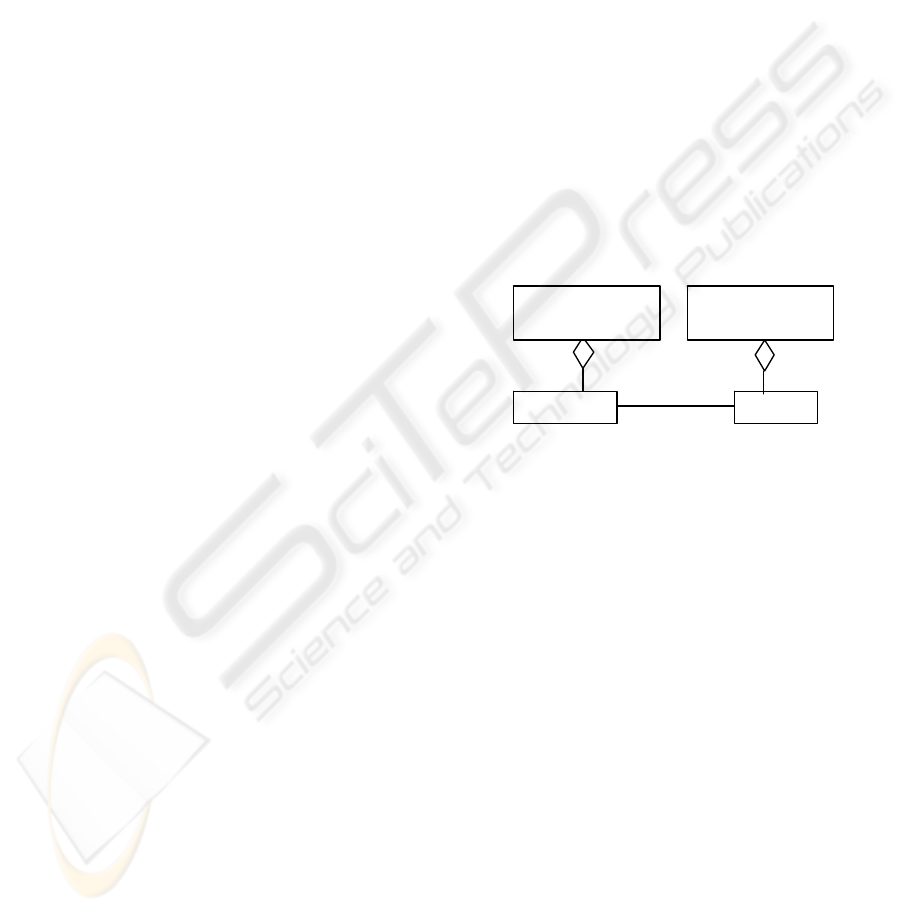
and also apply to Subsystem. Figure 8 describes a
class diagram that defines alternative
deploymentUnits. DeploymentUnitA is alternative to
DeploymentUnitB; if there are at least two elements
- a ServiceA in DeploymentUnitA, and a ServiceB
in DeploymentUnitB - those exclude each other.
Exclude is a new stereotype of UML association
introduced in this diagram.
4 RELATED WORK
Other researchers have tried to use and extend UML
notation for variability specification in PLA. The PL
developed by FSB (Flight Software Branch)
(McComas et al., 2000) is using UML. A special
symbol <<V>> to represent variability is created.
Elements that are not tagged by a <<V>> are
interpreted as common. This symbol is applied to
operation, attributes, and arguments of operations.
In KobrA (Atkinson et al., 2000), each Komponent
(KobrA component) in the framework is described
by a suite of UML diagrams and it’s specification
consists of four models. The structural, behavioral
and functional models constitute the specification
models as the Komponent is used in all applications.
The decision model contains information about how
the models change for the different applications and
thus describes the different variants. In PRAISE
project that focuses on the design and representation
of a PLA with UML (El Kaim et al, 2000), UML
package is used to represent a variation point or hot
spot with the stereotype <<hot spot>>. Also any
collaboration is tagged with a variant with “variation
point”. The usage of the package in this method to
represent variation points is not clearly stated. A
package is already used to designate a common core
component and a class that is contained in such a
component may also participate in a variation point.
Elements in a UML package must be contained in
only one package; therefore this did not allow the
package to be used to designate a variation point. It
is more desirable to use the UML package to model
common core components and use the UML tags to
identify the variation points that they contain.
0..1 0..1
*
*
1 «exclude» 1
«alternative»
DeploymentUnitB
«alternative»
DeploymentUnitA
ServiceA ServiceB
Figure 8: Alternative deploymentUnits.
SPLIT (Coriat et al, 2000) considers variation
points to have attributes and therefore uses the UML
classifier, class, to depict a variation point. The
variation point technique is very attractive in the
sense that variability is immediately visible in the
UML models. The mechanism associated to each
variation point defines the transformation to apply
when doing the derivation. However, using this
technique systematically requires development of
specific scripts and programs to manage it, since it is
not integrated in UML. By using a class to represent
a variation point gives the variation point attributes,
but not behavior. The attributes provide information
for a reuser to choose a variant. Webber (Webber
and Gomaa, 2002) goes a step further and shows a
reuser how to build a variant in variation point
model (VPM). Her approach provides an excess of
information to be managed by the designer in a low-
level specification. However, this research inspired
us in extending UML notation for our method.
A domain modeling method for software PL
with UML is described by (Gomaa and Gianturco,
2002). This allows the explicit modeling of the
ICSOFT 2008 - International Conference on Software and Data Technologies
238

similarities and variations among members of the
PLs or combinations of PLs. Various views of the
UML, in particular the use case view and the static
view are extended and used for modeling PLs and a
domain of PLs using a view integration approach.
The method introduces new stereotypes in modeling
the use case view. It also integrates the feature
model, which is used for modeling the common and
variable requirements in software PLs with the
UML. The UML package notation is used to depict
use cases that are grouped into the same feature.
Classes and class diagrams are used for static
modeling for the PL domain. UML stereotypes
distinguish between kernel, optional and variant
classes. Additionally, the <<alternative>> stereotype
is used to represent “1 and only 1” choices for
classes in the class diagram. Aggregation and
Generalization/Specialization hierarchies are used to
represent the static view of the domain model.
Variability in multiple-view models of software PL
has also been discussed in (Gomaa and Shin, 2003).
This paper uses UML notation for functional view,
which is represented through use cases, for static
model view through a class model and a dynamic
model view through collaboration model and
statechart model. This is a more general approach.
Here we propose UML notation extensions that are
applied particularly in modeling PLA for
middleware distributed services.
5 CONCLUSIONS
This paper has described how UML standard
concepts can be extended to address the challenges
of variability management in space of software
PLAs at conceptual level. A service based approach
has been considered in modelling architectural
views. In particular, a new UML profile has been
defined to be integrated in a systematic approach, a
quality-driven architecture design and quality
analysis method. Standard UML extensibility
mechanisms can be used to express diagrammatic
notations of each view of the architecture modeled
using the method. The detailed description of each
required extension presented in this paper would
allow a possible standardization of this profile.
Integrated use of a standard profile and a design
method as described here would allow extensive and
systematic use, maintenance and evolution of the
software PLAs. By using UML notation extensions,
our method models the variability, and hence
explicitly describes, where in the PLA views
software evolution can occur. A variation point
specification is needed in PLA views to
communicate to reusers where and how to realize a
PL-member-unique variant.
In the area of tool support a feasibility analysis of
the implementation of the new UML extensions was
also performed. We investigated whether or not
concrete CASE tool for software design supports the
new UML refinement. In the experiment we have
evaluated the Rational Rose RT tool (Rational,
2003). With regard to how the tool can be
configured or what other new components it needs,
our evaluation showed that the conceptual views are
affected by the missing required extension
constructs. We believe that with smaller adaptations
the required extensions can be made available in a
CASE tool.
REFERENCES
Atkinson C., J. Bayer, D. Muthig, 2000, Component-based
Product Line Development: The KobrA Approach,
Procs. of SPLC1, Kluwer Acad, pp. 289-310.
Coriat M., J. Jourdan, F. Boisbourdin, 2000, The SPLIT
Method,
Procs. of SPLC1, , pp. 147-166.
Dobrica L. and E. Niemela, 2008 An approach to
reference architecture design for different domains of
embedded systems,
Procs. of SERP 2008, CSREA
Press (to appear).
El Kaim, W., Cherki, S., Josset, P., Paris, F., 2000,
Domain Analysis and Product-Line Scoping: A
Thomson-SCF Product-Line Case Study,
Procs. of
SPLC
, Kluwer Acad.
Gomaa H., Shin M.E., 2003, Variability in Multiple-View
Models of Software Product Lines,
Procs. of SVM.
Gomaa H and M. Gianturco, 2002, Domain modeling for
World Wide Web based on Software Product Lines
with UML,
ICSR-7, LNCS 2319, pp. 78-99.
Jacobson I., M. Griss, P. Jonsson, 1997
, Software Reuse-
Architecture, Process and Organization for Business
Success, ACM Press.
Matinlassi M., E. Niemelä, L. Dobrica, 2002,
Quality-
driven architecture design and quality analysis
method – A revolutionary initiation approach to
product line architecture
, VTT Publications 456.
McComas, D., Leake, S., Stark, M., Morisio, M.,
Travassos, G., WhiteM
, , 2000, Addressing
Variability in a Guidance, Navigation, and Control
Flight Software Product Line,
Procs. SPLC1, PLA
Workshop.
OMG Unified Modeling Language Specification, 2003.
Purhonen A., E. Niemelä, M. Matinlassi, 2004,
Viewpoints of DSP software and service architectures,
Journal of Systems and Software.
Rational Rose RealTime CASE tools, http://www-
306.ibm.com/software/rational/.
Webber D. and H. Gomaa, 2002, Modeling variability
with the variation point model,
ICSR-7, LNCS 2319.
A UML-BASED VARIABILITY SPECIFICATION FOR PRODUCT LINE ARCHITECTURE VIEWS
239
