
A HW/SW CO-REUSE METHODOLOGY BASED ON DESIGN
REFINEMENT TEMPLATES IN UML DIAGRAMS
Masahiro Fujita, Takeshi Matsumoto and Hiroaki Yoshida
VLSI Design and Education Center, University of Tokyo, 2-11-16 Yayoi, Bunkyo, Tokyo, Japan
Keywords:
HW/SW reuse, System-on-a-Chip, HW/SW co-design, UML, architecture template, design template.
Abstract:
In general, a design refinement process of an electronic system including both hardware and software traces a
similar process of other systems in requirements analysis and system-level design. It is more true especially
when they belong to the same product domains. Therefore, we can reuse various documents easily by making
templates of the design refinement. In thispaper, we propose a methodology that generates those templates and
illustrate that the template made from the design refinement process of Compact-Flash (CF) memory interface
controller can actually be used in that of ATM switch. Both of them are typical HW/SW co-designs where
most of the control is performed by software. The generated templates can be applied to various designs which
have the structure of “IO + intelligent buffers”. We use UML to describe the design templates and prove the
efficiency of the use of the templates by showing the similarity of UML diagrams.
1 MOTIVATION
Due to the increased complexity of electronic systems
such as SoC, it is essential to have a design method-
ology where various HW/SW IPs can be easily and
precisely reused. Reuse of existing HW/SW designs
in all design levels is the key to improve design pro-
ductivity. A lot of studies have been made on reuse of
intellectual property (IP), but most of those deal with
the problems involved in RTL or lower design levels,
that is, they are discussing about only hardware im-
plementation reuse. Little attention has been given to
reuse of designs in requirements analysis and system-
level design where both hardware and software com-
ponents can be reused.
In this paper, we propose a reuse methodology
based on design refinement templates by which we
can reuse various documents on design decisions eas-
ily in higher-level design. In general, a design re-
finement process of an electronic system traces sim-
ilar process of other HW/SW combined systems in
requirements analysis and system-level design phase.
The tendency is more true especially when they be-
long to the same product domains. Therefore, in or-
der to improve productivity, it is important to create
templates of the design refinement processes which
contain many essential decisions on system design in-
cluding decisions on HW/SW partitioning. We use
UML (Unified Modeling Language (Booch, 1998)) to
describe the design templates since, with UML, we
can easily describe the design templates in require-
ments analysis and system-level design.
2 RELATED WORK
An SoC has one or more microprocessors inside
where some parts of the system can be executed as
software. Therefore, both hardware and software
parts of SoC should be seamlessly designed. As we
mentioned in Section 1, a lot of design reuse is being
done in SoC design, such as IP reuse. However, at the
beginning of the SoC designs, design decisions are
made in ad-hoc ways. To decrease the extra tasks of
refining designs and shorten the design period, much
more systematic design flows are needed. One of the
methodologies to realize the requirement is reusing
existing designs in earlier design stages. In the field
of software design, there is a methodology called de-
sign pattern, which categorizes existing designs, gen-
erates templates from them, and applies the templates
to other similar designs. Some researchers are try-
ing to apply the design pattern to software/hardware
co-design. Fernando Rinc´on et al proposed the de-
sign methodology in which data storages and data
computing algorithms are handled separately(Rinc´on
et al., 2005). Their design methodology is similar to
STL (Standard Template Library) in C++. In the de-
scription of algorithms, iterators are used to access
240
Fujita M., Matsumoto T. and Yoshida H. (2008).
A HW/SW CO-REUSE METHODOLOGY BASED ON DESIGN REFINEMENT TEMPLATES IN UML DIAGRAMS.
In Proceedings of the Third International Conference on Software and Data Technologies - SE/GSDCA/MUSE, pages 240-245
DOI: 10.5220/0001900102400245
Copyright
c
SciTePress
data storages, so that any kind of data storages can be
adopted. When the sufficiently various types of stor-
ages and algorithms are provided, the templates can
be easily applied to a new system. To apply the de-
sign methodology, however, designers have to come
up with the combination of the components in the li-
brary in ad-hoc ways. Also, it is difficult to design
a new system which significantly differs from the ex-
isting designs. To avoid these problems, design reuse
should be done in earlier stages and in larger scale.
3 OUR BASIC APPROACH
3.1 Specifications of UML
We use UML diagrams to represent our analysis and
design. UML is a standardized language that includes
nine types of diagrams to realize object-oriented anal-
ysis and design. By combining the use of (subset of)
these nine diagrams, object-oriented analysis and de-
sign methods can be realized, as presented in (Rum-
baugh et al., 1990; Booch, 1993; Jacobson, 2000).
UML, however, just provides a standardized way to
describe various diagrams related to object-oriented
analysis and design methodologies, and does not have
any particular ways to utilize the diagrams. There-
fore, there are many ways to use UML diagrams in
analysis and design, although the differences may not
be so large.
In our study, we use four types of the diagrams:
use-case diagram, class diagram, sequence diagram,
and state chart diagram. A use-case diagram is used
to analyze how the target system reacts and functions
to the environments (Fig. 2 and 6). A class diagram is
used to statically describe and analyze the target de-
signs by defining classes and their relationships(Fig.
3, 4, 7, and 8). A sequence diagram gives a snap-
shot of behaviors of the target system by defining se-
quences of messages among the objects inside the tar-
get system and the environments.
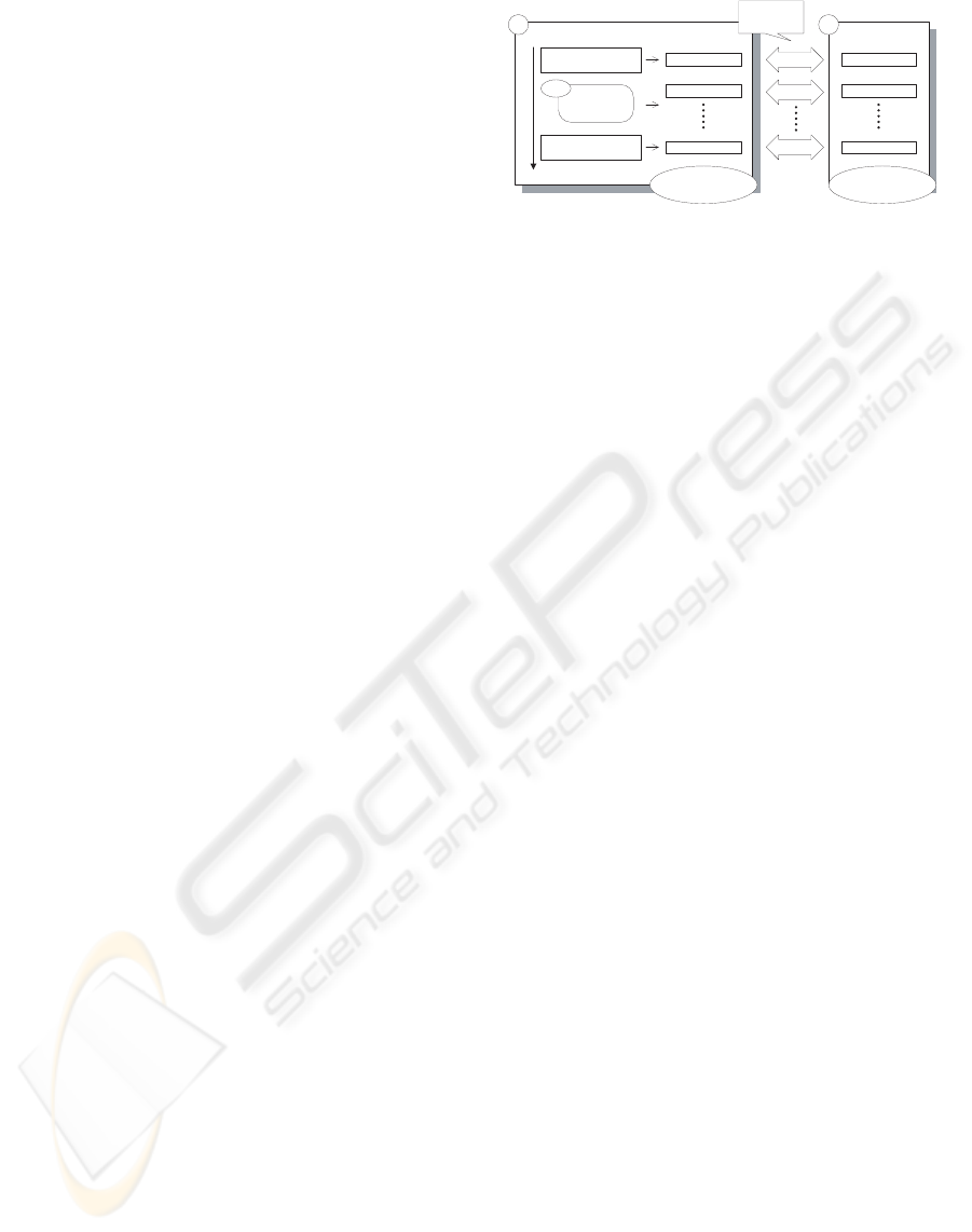
3.2 Basic Approach for Reuse
Our methodology appears in Fig. 1. It consists of two
phases as follows:
The First Design Phase. Requirements analysis, de-
cisions about functional structures and how to im-
plement them are performed manually. Some de-
sign templates are created based on the design of this
phase.
Reused Design Phase. The design refinement tem-
plates of the first phase are reused in this phase, and
The first design
Requirements analysis
System-level design
Processors
Memories
Buses
IPs
UML (Phase 1)
UML (Phase 2)
UML (Phase n)
Reused design
UML (Phase 1)
UML (Phase 2)
UML (Phase n)
Mapping
Mapping
Mapping
Existing design or
one in libraries
New UML
diagrams for new
design
1 2
Automate
with our tool
Refinement
Figure 1: Our basic approach for reuse.
new designs are performed semi-automatically. We
try to find similar designs by referring to existing de-
signs (including ones stored in libraries). Once some
similar designs are found, we try to apply the same
refinement steps for more detailed designs.
An important point to emphasize is the fact that
a design refinement process of an electronic system
usually traces a similar process of other systems in re-
quirements analysis and system-level design. There-
fore, one template is applicable to a lot of designs,
which results in the improvement of design produc-
tivity.
3.3 Design Flow for First Design
In the first design phase, designers extract require-
ments of the design target by use-case analysis, then,
describe class diagrams which realize the required be-
havior. At the beginning of the flow, designers start
with simple and abstracted diagrams. Along with the
refinement steps explained in the following, design-
ers make them into detailed ones taking characteris-
tic of the design target into account. UML diagrams
and associated notes about design decisions in each
refinement step are stored into the database and used
as templates for other designs later. Note that the dia-
grams/documents that are not finally adopted are also
stored into the database, since these alternatives can
be used for other designs in future. The detailed ex-
planation of the design flow for the first design is ex-
plained in Section 4.
3.4 Design Flow for Designs with Reuse
When there are existing designs available as design
template, designers search for designs which are sim-
ilar to a new design, and design it by reusing the re-
finement process of existing designs. Existing designs
are used in two ways in general. The first way is ap-
plied when the new design and the existing design are
similar to each other. In this case, the new design is
designed quickly by tracing the refinement process of
the existing design. In the second way, the existing
A HW/SW CO-REUSE METHODOLOGY BASED ON DESIGN REFINEMENT TEMPLATES IN UML DIAGRAMS
241
design is used in part. The existing design is used to
find classes and use-cases which can be used in the
current design. For example, from documents of ex-
isting designs, designers can find that classes of in-
terfaces most likely use a class of serial/parallel con-
version, a class of error collection, and so on. To de-
tect similarity or find typically used elements effec-
tively, existing UML diagrams have to be stored in
the format which is easy to handle with computers. In
this paper, we use XMI (XML Metadata Interchange)
(Keienburg and Rausch, 2001) as a format to handle
UML diagrams, because most of the UML drawing
tools are able to use XMI format. The detailed ex-
planation of the design flow for reused design is ex-
plained in Section 5.
4 CASE STUDY OF A NEW
DESIGN
Object-oriented design methodologies (OODMs)
have been widely adopted for better IP reuse and
also easier changes of specifications. With this in
mind, we try to apply object-oriented analysis and
design methodology for HW/SW co-design process.
Our OODM can generate these behavioral descrip-
tions from the start of the analysis of the target de-
sign. We applied our OODM for HW/SW co-designs
to the design of a Compact-Flash (CF) memory in-
terface controller, a typical example of HW/SW co-
design.
4.1 Use-Case Analysis and Scenario
Generation
So far, requirementanalysis for the target system have
been made by designers in rather ad-hoc ways espe-
cially for hardware part. In our design methodology,
we apply object-oriented analysis to this requirement
identification. We use use-case diagrams to list up
the required functionalities paying enough attentions
to interactions between inside and outside of the tar-
get designs. The goal is to clarify what functionalities
should be realized by the target designs.
In our OODM, the following two points must be
well taken care of for proper use of use-case diagrams.
The first point is that appropriate system boundaries
and actors should be identified. What are inside the
target designs and what are not must be clarified. Ac-
tors are basically either users of the target designs or
the things that can directly be manipulated by users.
The other point is that use-cases must be extracted
considering only functionality of the target designs.
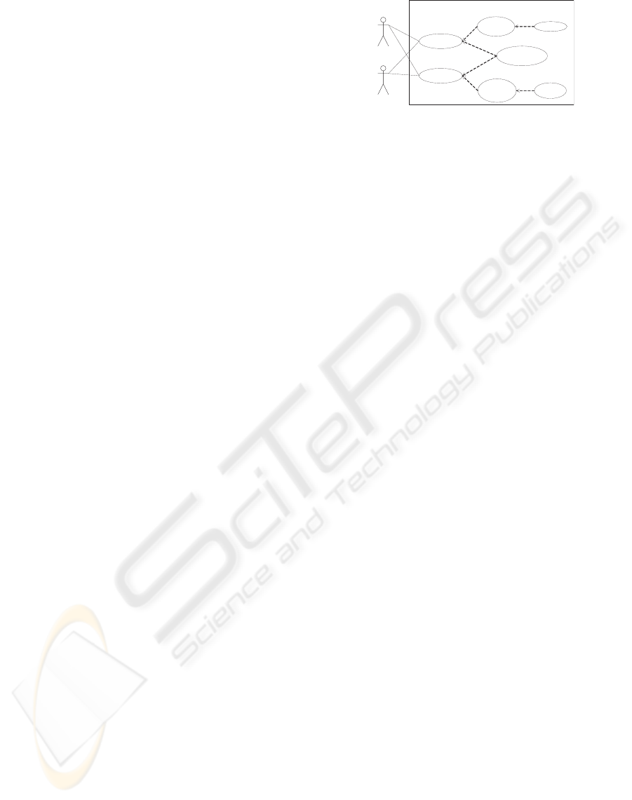
Design target
PCMCIA
Check
ecc
Add eccSerialize
Deserialize
Convert address
space
Load data
Save data
Flash memory
Figure 2: Use-case diagram of CF-memory interface.
The required performance for the target designs is not
included in the use-cases.
The next step is to describe scenarios for the use-
cases identified. The required behaviors to realize
each use-case should be analyzed. With the use-
cases and their related scenarios, rough specifications
of the target designs can be made. Use-case scenar-
ios should be generated with the following points in
mind.
• The words available for use-case scenario, the
contents to describe should be defined as rules be-
forehand. Use-case scenario should be written by
the rules. It is required to generate use-case sce-
narios and make them understoodby other design-
ers easily.
• When generating behaviors, alternative behaviors
should also be listed up and well considered. This
is good for reuses and redesigns as well.
• The results must be reviewed enough by other de-
signers as well.
In the case of CF-memory interface controller, one of
the generated use-case diagrams is shown in Figure 2.
4.2 Class Diagram in Requirements
Analysis
In order to realize the functionality defined in use-
case diagrams, we need to group together them and
identify a good set of problem domains. This is done
by using class diagrams. One way to do this is to
extract common “nouns” and “verbs” from the use-
case diagrams and scenarios, and assigning classes
to “nouns” and methods for classes to “verbs”. This
method is very effective especially in early phases of
analysis phases, although the quality of the extracted
class diagram pretty much depends on the quality of
the use-case scenarios.
With this class diagram for analysis, design reuses
as IPs and also changes of specifications can be rela-
tively much easier to be accommodated. Class dia-
grams for analysis phases should be generated with
the followings in mind:
ICSOFT 2008 - International Conference on Software and Data Technologies
242
Byte transfer
conversion
P/S conversionInternal Buffer
PCMCIA
Read()
write()
Flash memory
Read()
write()
data
request
address
data
PCMCIA IF Flash IF
Figure 3: Class diagram of CF-memory interface in the first
analysis phase.
• When generating candidates of classes, similar
words/concepts to the one shown in use-case sce-
narios should also be included.
• Each class should have clear responsibility in
terms of the functionality of the target designs. It
should also be considered whether each class gen-
erated can be reused easily or not.
• It is not good at all to directly map each use-case
scenario to a flow in class diagrams. If we do this
way, there will be too many relationships among
classes, and the resulting class diagrams will not
be easy to understand. Instead it is essential to cat-
egorize the functionality shown in the scenarios.
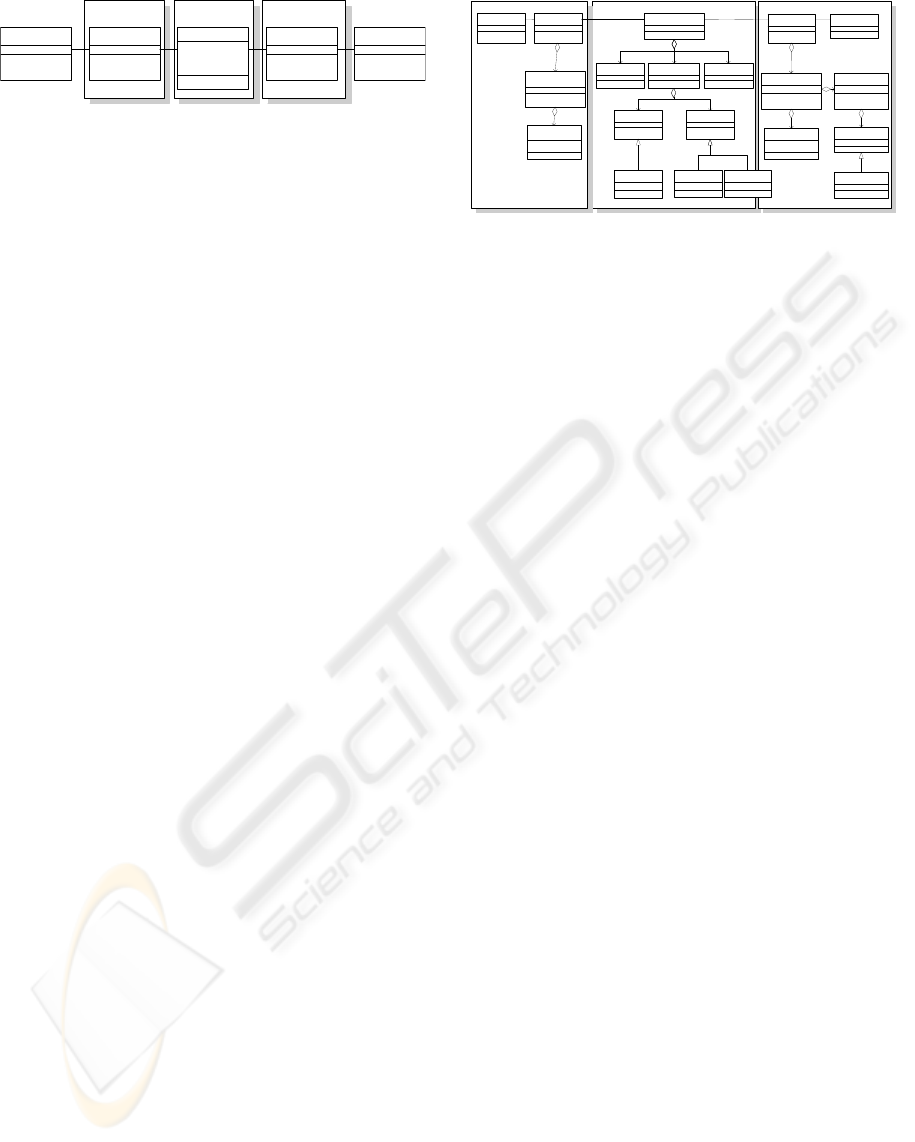
4.3 Class Diagram in System-Level
Design
Following the analysis phase, our OODM has the
second phase for system-level design considerations.
In this phase, based on the results of the analysis,
classes that should be implemented in hardware are
recognized and refined to have clear interfaces. Af-
ter this phase, each class in class diagrams can be
mapped into a function in SpecC (Gajski et al., 2000)
or SystemC (Accellera Organization, 2004) descrip-
tions, and they can be further processed for imple-
mentations.
When generating class diagrams for system-level
design, the following points must be considered:
• Sufficient sets of methods for each class to realize
the required functionality must be extracted.
• Things to be stored after each method should
be clarified. In the case of hardware implemen-
tations, they will be actual hardware facilities.
Since how they can be used and also shared are
critical for hardware implementation costs, life-
time analysis of the stored data is applied.
• Mainly for hardware realization, instances of
classes should also be generated, if multiple in-
stances of the classes are necessary. This is based
on hardware resource / performance trade-offs.
• For each class or instance of class, interfaces
must be clearly defined including what are ac-
tually transferred: pointers or actual data them-
Internal Buffer P/S conversionByte transfer conversion
Internal Buffer
addressManager
storageAddress
storageNumber
hostAddress
PCMCIA IO
receive()
send()
converte r
convert()
table
address
PCMCIA IO
Manager
sendByteData()
receiveByteData()
Byte transfer
converter
PCMCIAProtocol
dataManager
Flash IO Manager
sendSerialData()
receiveSerialData()
P/S converter
FlashProtocol
Flash IO
receive()
send()
eccManager
result
errorCheck()
addChecker()
error Checker
parity
FlashMemory
PCMCIA
requestManager
Figure 4: Class diagram for final design (CF memory IF).
selves. These interfaces are decried as newclasses
in class diagrams for system-level design. This
is essential for hardware implementation of the
classes and should be well considered.
Note that from this class diagram it is fairly easy
to generate system-level design descriptions.
4.4 Design Period and Design
Refinement Template
From the real and previous design experience on sim-
ilar hardware designs, we know that it needs about 12
man-months from behavior or RTL codings to the im-
plementation for this design. Also, the time spent for
analysis phase in the previous designs is about a cou-
ple of man-months although that was a very informal
process. Our proposed analysis and design method
took 3 man-months, and so we could say the time
spent is pretty much similar to the traditional informal
ones. Our method, however, generates lots of docu-
ments on design information including design deci-
sions. The documents can be utilized in other design
processes following our design methodology.
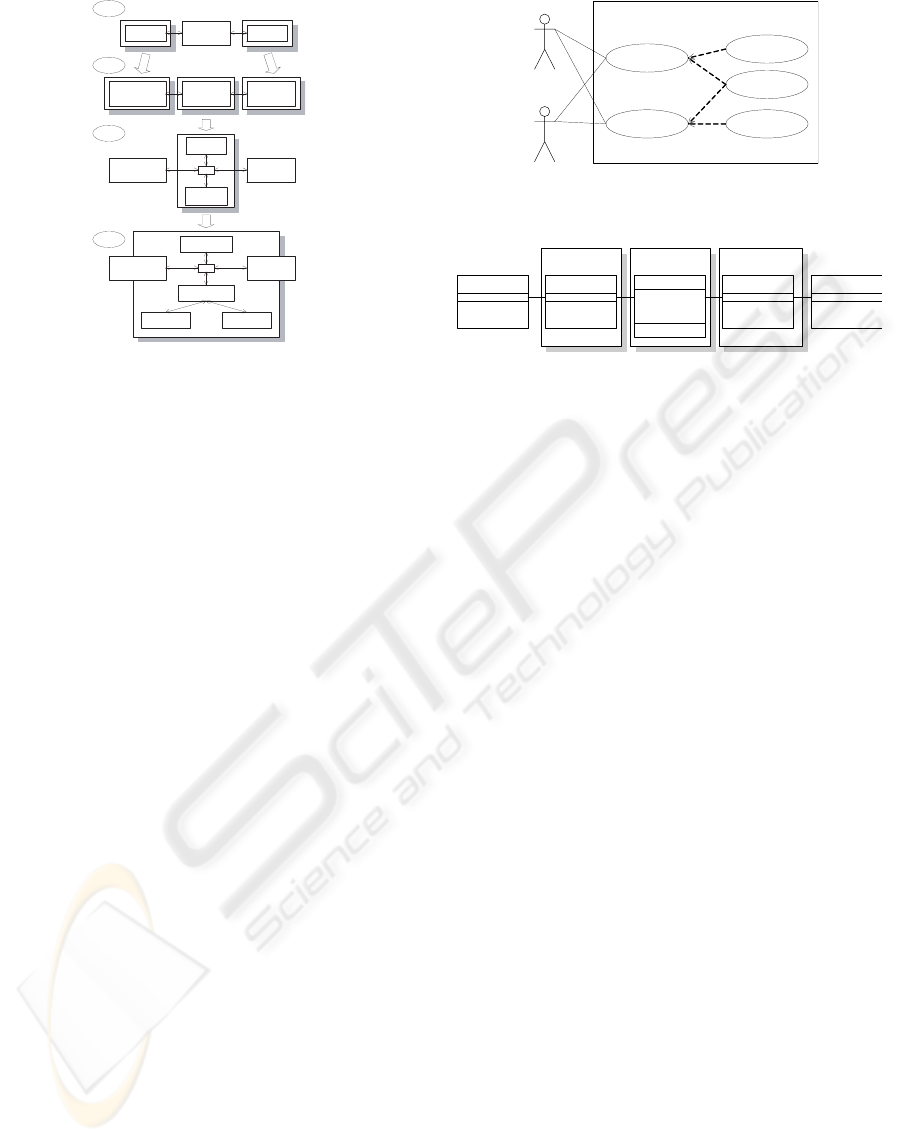
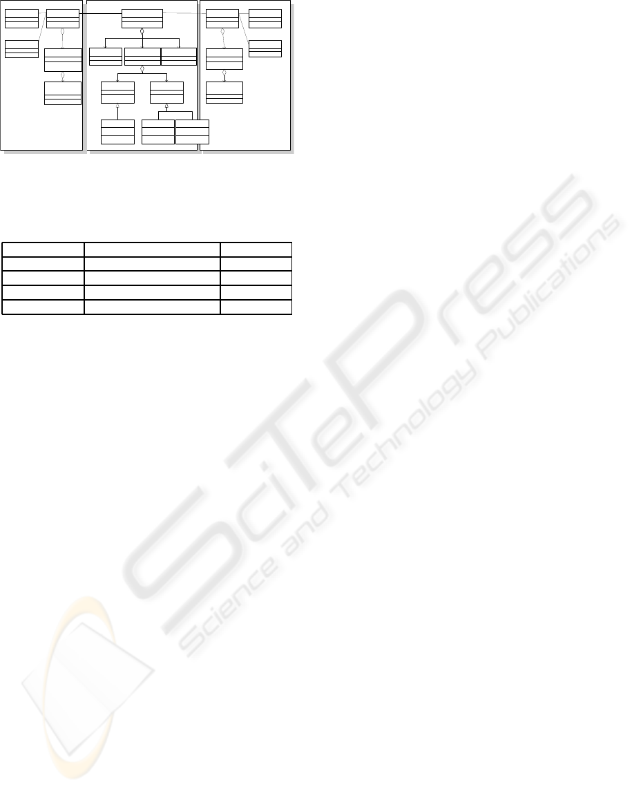
Figure 5 shows the design refinement process of
CF-memory interface controller using the simplified
class diagrams. In the phase 1, most primitive dia-
gram of the design is shown. In the phase 2, essential
factors of interface protocols for interfaces on each
side are reflected on the design. Then in phase 3,
the classes which represent address conversion and
required operation for using the flash memory are
added. Finally in phase 4, the classes to realize ad-
dress conversion are added into the diagram.
From these four diagrams, we can see that the se-
ries of works represent a generic design refinement
process of “IO + intelligent buffers” system. There-
fore, we can expect that some of the interface cir-
cuits are designed quickly by tracing this design re-
finement process. In the next section, we proof this
notion by applying the design refinement process of
CF-memory interface controller into the design re-
finement process of ATM switch.
A HW/SW CO-REUSE METHODOLOGY BASED ON DESIGN REFINEMENT TEMPLATES IN UML DIAGRAMS
243
Phase1
Phase2
Phase3
Phase4
PCMCIA
Internal
Buffer
Flash
Byte transfer
conversion
Internal
Buffer
P/S
conversion
Byte transfer
conversion
P/S
conversion
Address
Used
Address
Empty
Byte transfer
conversion
P/S
conversion
Address Used
Address Empty
R/W cont Counter
Figure 5: The design refinement template in interface cir-
cuits domain.
5 CASE STUDY OF DESIGN
WITH REUSE
5.1 Design Refinement Process of ATM
Switch
ATM switch has two inputs and two outputs of data
packets with control signals, and some functionalities
for routing the packets. The result of the requirement
analyses is shown in Fig. 6.
Comparing Fig. 7 with Fig. 3, we can say the two
diagrams are alike in the four points below.
• Both designs receive the data from a certain port
and send them to other ports without modifying.
• In both designs, the addresses are modified: ad-
dress conversion in CF-memory interface con-
troller and packet routing in ATM switch.
• A command is sent via particular port along with
data: via PCMCIA interface in CF-memory inter-
face controller and in the header attached to an
ACM packet in ATM switch.
• Input/output operations include serial/parallel
conversion.
From these four points, we apply the design re-
finement process of CF-memory interface controller
to that of ATM switch. First, we related Fig. 6 to the
phase 1 in Fig. 5. Then, we refined the design of ATM
switch referring to the process from the phase 1 to the
phase 2 in Fig. 5, and lead to Fig. 7. Fig. 3 and Fig. 7
look similar to each other, although some classes have
different name, attributes and methods, reflecting the
differences between requirements of the two design
targets.
Design target
Input1,2
Send out
data
Receive data
Output1,2
Routing
Serialize
Deserialize
Figure 6: Use-case diagram of ATM switch.
S/P conversion P/S conversionInternal Buffer
input
Send()
output
data
header
address
data
input IF output IF
Figure 7: Class diagram of ATM switch in the first analysis
phase.
We refined the design further in the same way. The
refinement processes correspond to the phase 2, 3, 4
in Fig. 5. We decided an abstract functional structure,
concrete implementation, and function modules in the
processes. Not only class diagrams but also sequence
diagrams are created at the same time to check the
behavior of the system in each design refinement step.
Figure 8 shows the most refined version of the
class diagram for ATM switch. This diagram is used
as input for C-based design.
5.2 Evaluation of Reuse Methodology
We evaluated the performance of the reuse and the
amount of works spent to design ATM switch. We
evaluated how much amount of the design of CF-
memory interface controller is reused by comparing
Fig. 4 with Fig. 8. Comparing the two class dia-
grams, the classes in the two diagrams can be catego-
rized into three categories.
Classes whose Name, Attributes, Methods are not
Modified. They are the ones that are not modified in
the design refinement process of ATM switch.
Classes whose Name, Attributes or Methods are
Modified. In this category, classes that have the cor-
responding classes in the other class diagram are in-
cluded, according to their functions or their place-
ments in the diagram. They are the same classes as
the counterparts in abstract diagrams, and get apart in
the design refinement process.
Classes Deleted or Newly Created. These classes
are specific to each target design. In designing ATM
switch, some classes are newly generated and refined
in the process explained as the first design phase.
ICSOFT 2008 - International Conference on Software and Data Technologies
244
Internal Buffer S/P conversionP/S conversion
internalBuffer
routingDecision
outputPort
portNumber
inputPort
inputIF
receive()
selector
select()
fifo
address
inputManager
P/S conversion()
P/S converter
dataManager
outputManager
S/P conversion()
S/P converter
outputIF
send()
output1
output2
input1
input2
headerAnalyzer
Figure 8: Class diagram for final design (ATM switch).
Table 1: The number of reused class in class diagrams for
final design.
CF memory IF → ATM switch
5 Reused without changing 5
11 Reused with a few changes 13
4 Added manually 1
20 Total 19
Table 1 shows how many classes correspond to
each category. If we define the reused classes as the
classes which categorized into the first and the sec-
ond categories, we can say that 80 % of the classes
in CF-memory interface controller are reused in ATM
switch. Therefore, it seems reasonable to conclude
that our proposed methodologycan shorten the period
for requirements analysis and system-level design. In
fact, the analysis and design of the ATM switch was
completed in only two man-weeks.
In addition, we strongly believe that reusing IPs
and changing specifications can be much easier to
be accommodated in our methodology, since we fi-
nally have various documents in UML diagrams for
not only final designs but also alternative designs.
6 CONCLUSIONS
In this paper, we proposed a design methodology
which reuses the process of requirement analysis and
system-level design refinement both for hardware and
software designs. We used UML to describe each
step of design refinement process, which resulted in
that designers could easily describe design decisions
and communicate to other designers. Also, applying
the object oriented analysis, we can pick up require-
ments thoroughly, accommodate to changes of speci-
fications, and carry out IP reuse easily.
In our design methodology, documents such as
UML diagrams and notes in natural languages are
reused as design templates in later designs. At the
first design, our design methodology requires almost
the same amount of works as conventional design
flows. From the next similar design, we can signif-
icantly decrease design period by reusing the design
process of the previousdesigns. In the experiment, we
designed CF-memory interface controller and found
that the design process can be categorized into “IO +
intelligent buffer”. Then, based on this observation,
we designed ATM switch tracing the design process
of CF-memory interface. The design of ATM switch
took only 2 man-weeks, and reused 80 % of the de-
sign from CF-memory interface controller design.
As our future work, we will implement and auto-
mate our methodology such as detecting similarity be-
tween diagrams and searching for the related classes.
Also, we should consider to define how to describe
notes on design decisions in some formal way.
REFERENCES
Accellera Organization, I. (2004). SystemC 3.1a
Language Reference Manual. available from
http://www.systemc.org/.
Booch, G. (1993). Object-Oriented Analysis and Design
with Applications (2nd Edition). Benjamin Cummings
Publishing Company.
Booch, G. (1998). The Unified Modeling Language User
Guide. Addison-Wesley Publishing.
Gajski, D., Zhu, J., D´omer, R., Gerstlauer, A., and Zhao, S.
(2000). SpecC: Specification Language and Method-
ology. Kluwer Academic Publishers.
Jacobson, I. (2000). Object-Oriented Software Engineering.
Addison-Wesley Publishing Company.
Keienburg, F. and Rausch, A. (2001). Using xml/xmi for
tool supported evolution of uml models. In Proc. of
34th Annual Hawaii International Conference on Sys-
tem Sciences. IEEE.
Rinc´on, F., Moya, F., Barba, J., Carlos, J., and L´opezR
(2005). Model reuse through hardware design patterns
templates. In Proc. of Dsign Automation and Test in
Europe.
Rumbaugh, J. R., Blaha, M. R., Lorensen, W., Eddy, F.,
and Premerlani, W. (1990). Object-Oriented Modeling
and Design. Printice Hall.
A HW/SW CO-REUSE METHODOLOGY BASED ON DESIGN REFINEMENT TEMPLATES IN UML DIAGRAMS
245
