
ANALYZING DECENTRALIZED GOVERNABILITY OF BUSINESS
PROCESSES BY EXTENDED PETRI NETS AND MODAL LOGICS
Takashi Hattori
NTT Communication Science Laboratories, 2-4, Hikaridai, Seika-cho, Keihanna Science City, Kyoto, Japan
Hiroshi Kawakami, Osamu Katai, Takayuki Shiose
Graduate School of Informatics, Kyoto University, Yoshida Honmachi, Sakyo, Kyoto, Japan
Keywords:
Decentralized Control, Discrete Event System, Petri Net, Modal Logic.
Abstract:
We introduce a novel notion of decentralized governance structure of event-driven processes together with
the notions of their behavioral and structural correctness. The ways for attaining correct process behavior, as
well as the notion of decentralized governability, are examined based on temporal logical analyses of process
behavior via Petri net representations of process structures. Also, the deontic and temporal logical prescrip-
tions of normative constraints (tasks) on the processes are introduced that are then translated into extended
hierarchical Petri net structures. The conflicts among these tasks are examined on this hierarchical structure.
1 INTRODUCTION
As e-businesses grow, users have gained power in
obtaining information and combining various service
applications. For instance, if a user decides to go on
a trip, s/he may use an access map, train informa-
tion, a hotel search, and a defrayment service. Thus,
users are nowadays active, unlikethose of the past that
only passively followed the line prepared by service
providers. In other words, a single service provider is
not as powerful now as before, and processes are not
as centralized as before.
This paper proposes a theoretical framework for
such decentralized multi-agent (in this case, users and
service providers) systems that can represent agents’
behavior and their policies or control rules. The be-
haviors of agents are represented by a Petri net (Pe-
terson, 1981), which offers rich mathematical analy-
sis, and introducing modal logics (Hughes and Cress-
well, 1968) enables us to represent policies and con-
trol rules. It is known that a Petri net is conventional
and now its successors, e.g., a Unified Modeling Lan-
guage (UML) (Saldhana and Shatz, 2000), are popu-
lar tools for system modeling. Applying a Petri net is
still a hot topic for those researchers that place empha-
sis on checking the behavior of system design (Hu and
Shatz, 2004). Modal logics, e.g., temporal and deon-
tic logics, are also known as conventional theories.
They have been applied to several systems (Black-
burn et al., 2006) and their theoretical studies still
progress (Nute, 2004).
For further development of e-business, decentral-
ized governance is inevitable. Growing numbers of
services and applications may lead to overlap of ser-
vices, which may sometimes cause interference. Our
framework enables us to check the existence of inter-
ference among services’ control and user’s policies.
Furthermore, it shows us how to eliminate the inter-
ference.
The rest of this paper consists of the followingsec-
tions. Section 2 introduces the outline of the frame-
work. In this framework, components of a target sys-
tem are classified into two portions from the view-
point of whether it is a prefixed structural element or
an element that may change over time like users’ poli-
cies and service providers’ control rules. The former
portion is encoded into a conventional Petri net. The
latter half is first represented by modal logic formulae,
which are then translated into extended Petri nets that
we call “task unit graphs.” The two portions are then
integrated into a single extended Petri net. In section
3, the framework introduced in section 2 is applied to
the modeling of decentralized governance problems.
Based on the model, we discuss the correctness of
process behavior and centralized/decentralized gov-
ernability in sections 4 and 5.
29
Hattori T., Kawakami H., Katai O. and Shiose T. (2008).
ANALYZING DECENTRALIZED GOVERNABILITY OF BUSINESS PROCESSES BY EXTENDED PETRI NETS AND MODAL LOGICS.
In Proceedings of the International Conference on e-Business, pages 29-36
DOI: 10.5220/0001907500290036
Copyright
c
SciTePress

2 MODELING SYSTEMS BY
PETRI NET AND MODAL
LOGIC
This section proposes a method for modeling decen-
tralized systems based on a kind of Petri net and
modal logic. Hereafter, we present the procedure of
system modeling by using an example of a travel-
ers’ decision on itineraries with the assistance of e-
applications.
Example System. Assume that in the near fu-
ture, many e-applications will work as sophisticated
agents, and help users by cooperating with each other.
Now a traveler has arrived at Porto station. S/he
enters an internet cafe, and launches the following
agents: e-landmark map agent (A1), e-hotel search
(A2), e-train connection information (A3), and an e-
defrayment system (A4).
S/he has two itineraries to decide on. One is find-
ing a hotel to stay at and a way to get there by train.
The other is finding sightseeing spots and how to ac-
cess them. In the former mission, s/he first searches
for a hotel by using A2, which submits the hotel’s lo-
cation to A3, as well as her/his current location. A3
determines the route between Porto and the nearest
station to the hotel. After the route is decided, defray-
ment is executed by A4. In the latter mission, s/he
decides on two scenic sites s/he wants to visit with
the help of A1, which hands over the location of the
sites to A3 and defrayment is again executed by A4.
Anyway, A3 requires two locations and searches for
the optimal route between them.
2.1 Petri Net Representation of
System’s Event-Driven Aspect
A Petri net is known as a conventional representation
scheme for modeling a physical structure and event-
driven behavior of discrete event systems (Karatke-
vich, 2007). It is also known that a k-bounded stan-
dard Petri net can be translated into an equivalent 1-
bounded Petri net. We employ a 1-boundedone called
the condition/event system (C/E system) (Reisig,
1982) where a transition can only fire if all “its output
places” are empty.
For instance, the example described above is the
case where the upper-bound of “the number of stored
locations” is two (2-bounded). Thus it can be mod-
eled as a C/E system as shown in Fig. 1, where a token
in place P
i
means the following:
P
1
: Both A1 and A2 are idling,
P
2
: A1 is working,
P
3
: A2 is working,
P
4
: cache memory of A3 stores a location,
P
5
: second memory of A3 stores a location,
P
6
: A4 is idling,
P
7
: A4 is working.
Each of the transitions τ
2
and τ
4
means a submission
of the location of a hotel or a landmark, τ
5
means the
“data transfer from the cache to the second memory”
and “flushing cache,” and the firing of τ
6
makes A3
search for a train connection between two locations
and give train fees to A4.
τ1 τ2
τ3
τ4
τ5
τ6
τ7
P2
P1
P3
P4
P5
P6
P7
A1
A2
A3
A4
agent. territory
A1 P
1
, P
2
, τ
1
, τ
2
A2
P
1
, P
3
, τ
3
, τ
4
A3
P
4
, P
5
, τ
5
, τ
6
A4
P
6
, P
7
, τ
6
, τ
7
Figure 1: Petri net representation of a decentralized discrete
event system.
When we correspond a place of a C/E system to
a proposition, we can represent the true/false value of
the proposition by putting/removing a token in/from
the place. In this case, each transition leads the value
alteration of the proposition. For instance, in Fig. 1,
the firing τ
6
leads P
4
, P
5
, P
6
to turning from true to
false, and P
7
to turning from false to true.
2.2 Modal Logic Representation of
Tasks
Next, we represent the tasks that state “when the fo-
cused state should be true” as propositions by intro-
ducing temporal and deontic logic.
2.2.1 Temporal Modalities
A temporal logic is given by the propositional logic,
modal operators, and an axiom system. This paper
employs the following modal operators:
ICE-B 2008 - International Conference on e-Business
30

T A: A will be true at the next state S
1
,
G A: A will be true from now on S
0
, S
1
, S
2
, ··· ,
F A: A is true at S
0
, or will be true at some time
in the future S
i
(i > 0),
AU B: B is true at S
0
or A will be true from now
on until the first moment when B will be the
case,
where A, B denote logic formulae, and S
0
/S
i
(i > 0)
mean current/future states (worlds) respectively.
Axiom systems of temporal logic vary depending
on the viewpoint of time. This paper employs one
of the discrete and linear axiom systems K
SU
(Katai
and Iwai, 1983), which is an extension of the mini-
mal axiom system K
t
(Rescher and Urquhart, 1971).
Introducing Y (yesterday) as the mirror image of T
(tomorrow), the axiom system claims that ⊢ T ¬A ≡
¬T A, ⊢ Y ¬A ≡ ¬Y A, and ⊢ T Y A ≡ Y T A ≡ A. In-
troducing S (since) as the mirror image of U (until),
G A ≡ AU ⊥, where ⊥ denotes the contradiction, and
F A ≡ ¬G ¬A, K
t
is rewritten as
⊢ AU B ≡ B∨ (A∧ T (AU B)), (1)
⊢ AS B ≡ B∨ (A∧ Y (AS B)),
⊢ { (A ⊃ T (A∨ B))U C} ⊃ {A ⊃ AU (B∨C)},
⊢ { (A ⊃ Y (A∨ B))S C} ⊃ {A ⊃ AS (B∨C)},
where A, B and C denote logic formulae.
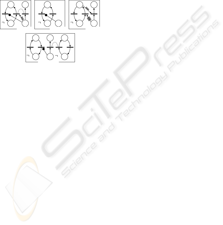
Regarding state transitions in the future, there are
two aspects, i.e., b (branching) and l (linear), thus the
modes G and F are more precisely defined as (Katai,
1981):
G
b
A: A will necessarily be persistent,
G
l
A: A will possibly be persistent,
F
b
A: A will possibly be the case,
F
l
A: A will necessarily be the case.
Figure 2 illustrates those modes where each circle de-
notes a state, each arc denotes a state transition, and
the black circles mean that the state holds A.
Furthermore, U also can be branching (U
b
) or lin-
ear (U
l
) as shown in Fig. 3. In the figure, each black
circle means that B is true in that state, and the letter
A means that A is true in that state . Among them, the
following relations are established; G
b
A ≡ AU
b
(B ∧
¬B) ≡ ¬F
b
¬A, G
l
A ≡ AU
l
(B∧ ¬B) ≡ ¬F
l
¬A.
2.2.2 Deontic Modalities
Understanding the system’s behavior by temporal
logic is of an “objective” view of the focused propo-
sition. To represent our “subjective” intention or pur-
pose, such as how the propositions should behave,
i.e., the control rule (or task), we introduce deontic
modalities:
GbA FbA
: A holds
GlA FlA
Figure 2: Alethic modes of state transitions.
AUbB AUlB
A
A
A
A
A
A
A
A
A
A
: B holds
: A holds
A
Figure 3: Branching and linear modes of U .
O A: A is obligatory,P A: A is permitted.
The axiom system we adopt here for O and P is that
of SDL (standard deontic logic), which defines O A ≡
¬P ¬A, and claims ⊢ O A ⊃ P A, and ⊢ O (A ⊃ B) ⊃
(O A ⊃ O B).
Some control rules and specifications of systems
can be translated into the combinations of temporal
and deontic modes by using “translation templates”
such as
O F A: A has to be true in the future,
P G A: A can be always true.
They correspond to alethic modes F
l
A and G
l
A re-
spectively.
2.3 Network Representation of Tasks
We translate the task represented by modal logic
into an extended Petri net, which we call a “task
unit graph,” by introducing four types of special arcs
shown in Fig. 4.
Request of firing synchronization
Prohibition of firing
Compulsion of firing at the next step
Compulsion of firing in the future
(a)
(b)
(c)
(d)
Figure 4: Special arcs for control of transition firing.
ANALYZING DECENTRALIZED GOVERNABILITY OF BUSINESS PROCESSES BY EXTENDED PETRI NETS
AND MODAL LOGICS
31
These arcs are placed from a place to a transition.
They function whenever the place holds a token and
the transition satisfies the firing condition, but they
differ from regular arcs of the conventional Petri net
on the following points. First, they do not transfer to-
kens from places to arcs. Next, if there are multiple
special arcs from the same place, all of them are acti-
vated simultaneously. As a result, simultaneous firing
of multiple transitions is permitted at the same state.
A
A
free A
A
A
A
free
(a) OTA (b) OGA (c) OFA
A
A
free
B
B
(d) O(AUB)
Figure 5: Examples of task unit graph.
Figure 5 shows examples of task unit graphs, and
these net representations are derived by a systematic
analysis of logical representations of tasks. For in-
stance, consider a task O (AU B). A has to be true from
now on until B will be the case. If B is the case at S
0
,
this task is accomplished, else if ¬A∧ ¬B at S
0
, this
task cannot be accepted due to Eq. (1). If A∧ ¬B at
S
0
, A should be maintained and O (AU B) also has to
be the case at S
1
. In each case, O (AU B) at S
0
pro-
hibits the alteration from A to ¬A, so an arc of “prohi-
bition of firing” is placed from the place of O (AU B)
to the “transition of the alteration from A to ¬A.”
3 DECENTRALIZED SYSTEM
STRUCTURE
This paper defines the characteristics of decentralized
systems as
• each agent has its own territory,
• each control task is given to one of these agents,
• a task can control a transition within the territory
of the agent to whom the task is given.
Figure 1 is an example of decentralized system. It
consists of four agents who are in charge of managing
the sub tasks denoted by thick broken circles in Fig. 1.
Assume that the traveler has her/his own policy
for using e-agents and adopts them as control rules in
order to fulfill her/his needs such as:
PP1: defrayment must not be done simultaneously
with submission of a landmark/hotel location;
PP2: hotel search is always followed by a landmark
search;
PP3: submission of either a hotel or a landmark is
accepted only if the first cache of the train search
is empty;
PP4: the system should request a hotel submission
some time in the future before the end of a set of
executions.
Each task associated with each agent is activated
by the firing of the corresponding transition in its ter-
ritory, e.g., in this case we have the following tasks
represented in temporal deontic logical forms,
PP1: τ
6
activates O
2
(P
1
U P
6
)
PP1: τ
1
or τ
3
activates O
4
(P
6
U P
1
)
PP2: τ
4
activates O
2
(¬P
3
U P
2
)
PP3: τ
2
or τ
4
activates O
1
(P
1
U (¬P
4
))
PP4: τ
1
activates O
2
F P
3
where O
i
stands for the obligation for agent Ai.
Not every task corresponds to a specific transition.
Some tasks are translated into logical forms that are
not activated by a transition but are always activated.
For example, a rule
PP0: Once the defrayment process is finished, agent
A2 should not submit a hotel location until the
cache memory flushes its contents to the memory,
is resident and translated into
O
2
G ({(¬P
3
)U (¬P
4
∧ P
5
)}S (¬P
7
)).
Defining Q ≡ ¬P
4
∧ P
5
, H ≡ ¬P
3
U Q, PP0 can be
represented as O
2
G (HS(¬P
7
)), which derives an ex-
tended Petri net representation as shown in the left
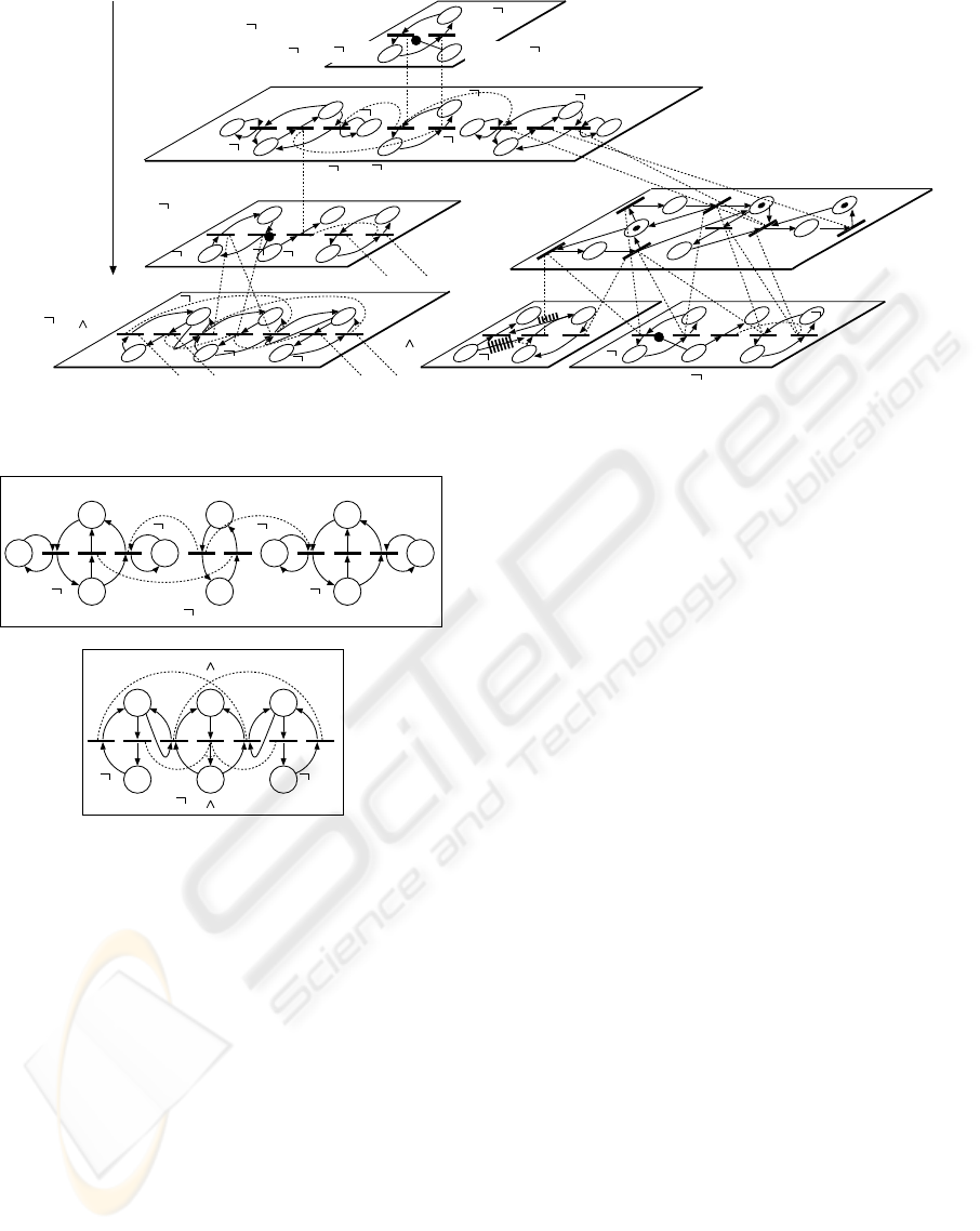
part of Fig. 6 (Katai, 1981).
It consists of module nets reflecting its subtasks,
and they are joined with linkage relations prescrib-
ing concurrent (simulations) firing of linked relations
shown in Fig. 4 (d). It should be noted that the transi-
tive closure of these linkage relations links the task in
analysis with the target system, which is shown in the
middle part of Fig. 6. In the figure, task unit graphs
showing S and ∧ (conjunction) are employed. Their
general types are defined as shown in Fig. 7.
4 CORRECTNESS OF SYSTEM
AND ITS BEHAVIOR
4.1 Behavioral Corrections
A system can be regarded to behave correctly
iff
it
satisfies the following conditions:
ICE-B 2008 - International Conference on e-Business
32
A B
O2G(HS( P7))
HS( P7)
(HS( P7))
H
P7
H
P7
H
P7
H
P7
Q
P3
Q
P3
τ3τ4
P5
P5
P4
P4
Q
Q
H
H
τ5τ6
τ2τ5
Q= P4 P5
or
H= P3UQ
Hierarchical Decomposition
of Task O2G(HS( P7))
HS( P7)
(HS( P7))
τ1
τ2
τ3 τ4
τ5
τ6
τ7
P2
P1
P3
P4
P5
P6
P7
O2FP3
P3
P3
free
P4
P4
P1
P1
O1(P1U P4)
free
Target System
Figure 6: Hierarchical extended Petri net representation of the system with tasks.
A B
ASB
B
A
(ASB)
A
A
B
B
A
A
B
B
or
(A B)
A B
Figure 7: Task unit graph of S and that of “∧” (conjunction).
Definition 1 (Correctness of State Transition Se-
quence). A sequence of state transition is correct
iff
the following cases do not occur along with this infi-
nite sequence:
1. Any proposition A does not occur just after the
state where O
i
T A (O
i
G A, O
i
(AU B)) is given to
an agent i.
2. A never happens to the case after the state (until B
is the case) where O
i
F A (O
i
(AU B)) is given.
4.2 System Correctness and its
Characterization
We have two kinds of system corrections as follows:
Definition 2 (Strong Correctness of System). A
system is strongly correct
iff
any state transition se-
quence generated by the system (system behavior) is
correct. Namely, there is no need to control the sys-
tem.
In terms of temporal or deontic logical expres-
sions, the above is characterized as:
G
b
(¬C), G
b
(O
i
F A ⊃ F
l
A),
G
b
{O
i
(¬(AU B)) ⊃ ¬(AU
l
B)},
where C is a state of contradiction.
We have practically more important and weaker
notions of system correctness as follows:
Definition 3 (Weak Correctness - Centralized Gov-
ernability). A system is called weakly correct
iff
we can extend an arbitrary generated state transition
sequence so that it is correct by appropriately execut-
ing the firing of permitted (legal) transitions This can
be characterized as
G
b
(¬C), G
b
(O
i
F A ⊃ F
b
A),
G
b
{O
i
(¬(AU B)) ⊃ (¬(AU
b
B))}.
In terms of the state transition diagram, the current
notion of strong correctness can be characterized as:
Theorem 1 (Strong Correctness of System). A
system is strongly correct
iff
the following hold:
(a) for an arbitrary terminal state of its state transition
diagram, there is no task associated with it of the
form of O
i
T A, and if O
i
F A is present there, then
A is also present on that state, and if O
i
(¬(AU B))
is present there, then both ¬A and ¬B are also
there;
(b) for an arbitrary cycle (circuit) of its state transi-
tion diagram, the following hold:
ANALYZING DECENTRALIZED GOVERNABILITY OF BUSINESS PROCESSES BY EXTENDED PETRI NETS
AND MODAL LOGICS
33

(b.1) if O
i
F A is present at a state in the cycle,
then A is also present at possibly another state
in the cycle;
(b.2) if O
i
(¬(AU B)) is present on a state s in the
cycle, then there is also state s
′
such that ¬A
holds on s
′
and there is no state between s and
s
′
at which B holds.
For characterizing weak correctness, we intro-
duce the notion of condensation of directed graphs by
“strong components” that are defined as their bidirec-
tionally connected maximal subgraphs (Harary et al.,
1965).
Theorem 2 (Weak Correctness of System). A sys-
tem is weakly correct
iff
the following hold:
(c) the same as condition (a) in Theorem 1;
(d) for every terminal strong component of its state
transition diagram the following hold:
(d.1) if O
i
F A is present in a state at the compo-
nent, there is a state (and possibly another) on
which A holds;
(d.2) if O
i
(¬(AU B)) is present in a state s, then
there is a state s
′
on which ¬A holds and there
is a path joining s and s
′
along which B never
holds.
5 DECENTRALIZED
GOVERNABILITY OF
PROCESSES
5.1 Method of System Correction
From the above results, we will have two ways of
making an arbitrary system to behave correctly:
(i) to make the system strongly correct,
(ii) first to make the system weakly correct and then
to control it so that its behavior (generated state
transition sequence) becomes correct.
In the first approach, there is no more need to control
it, i.e., any state transition sequence yielded from it is
surely correct. In the latter approach, weak correct-
ness itself is merely a precondition on governability
and there is still need for supplementary control on
permitted transitions. In other words, weak correct-
ness guarantees the possibility of this supplementary
control. In this paper we will pursue the latter ap-
proach, which seems to be of more practical impor-
tance than the former.
5.2 System Correction in Terms of State
Transition Diagram
It can be readily seen that the following modifications
on state transition diagrams are necessary for making
systems be weakly correct:
(ii.1) remove the terminal states from the diagram at
which either a task
O
i
T A is present, or
O
i
F A and ¬A are present, or
O
i
(¬(AU B)) is present and at least one of ¬A or
¬B is absent;
(ii.2) remove the terminal strong components, which
include
O
i
F A but ¬A, or
O
i
(¬(AU B)) is present but ¬A, or
O
i
(¬(AU B)) at a state s and ¬A at a state s
′
such
that any path from s to s
′
includes a state at
which B does not hold.
The above operations on state transition diagrams
need to be applied repeatedly because removal of ter-
minal states or strong components will yield different
terminal states and strong components. The opera-
tions proceed until there is no need for them. If we
still have remaining states in the diagram, the system
is modified to be weakly correct.
An Example of Conflict Detection. The typical
conflicts are observed among tasks. Figure 8 shows
the diagram of a portion of the sequence of state tran-
sitions of the target system with the initial state S0,
which holds P
1
and P
6
, and is in charge of tasks PP0,
1, 2, 3, and 4. Table 1 shows the markings of each
state where “◦” means a normal token and “•” means
an active token, which constraints other tokens.
τ1
τ2
τ2
τ4
τ5
τ6τ7
S5
S5
S4
S4S5
S3
S5S6
S2
S6S0
S1
S7
τ3
τ1
τ1
τ6τ7 τ2
τ4
’ ’
’’
’’’’
Figure 8: State transition diagram of the system in table 1.
The terminal state S5 is removedfrom the diagram
by the operation (ii.1) since O F P
3
is required but ¬P
3
at the state. As a result, there is no “terminal strong
component” in the diagram and the system becomes
weakly correct.
The conflict in the state S5 can be detected by
tracing synchronized firing linkages (broken lines in
Fig. 9) as mutual interferences among tasks. In state
ICE-B 2008 - International Conference on e-Business
34
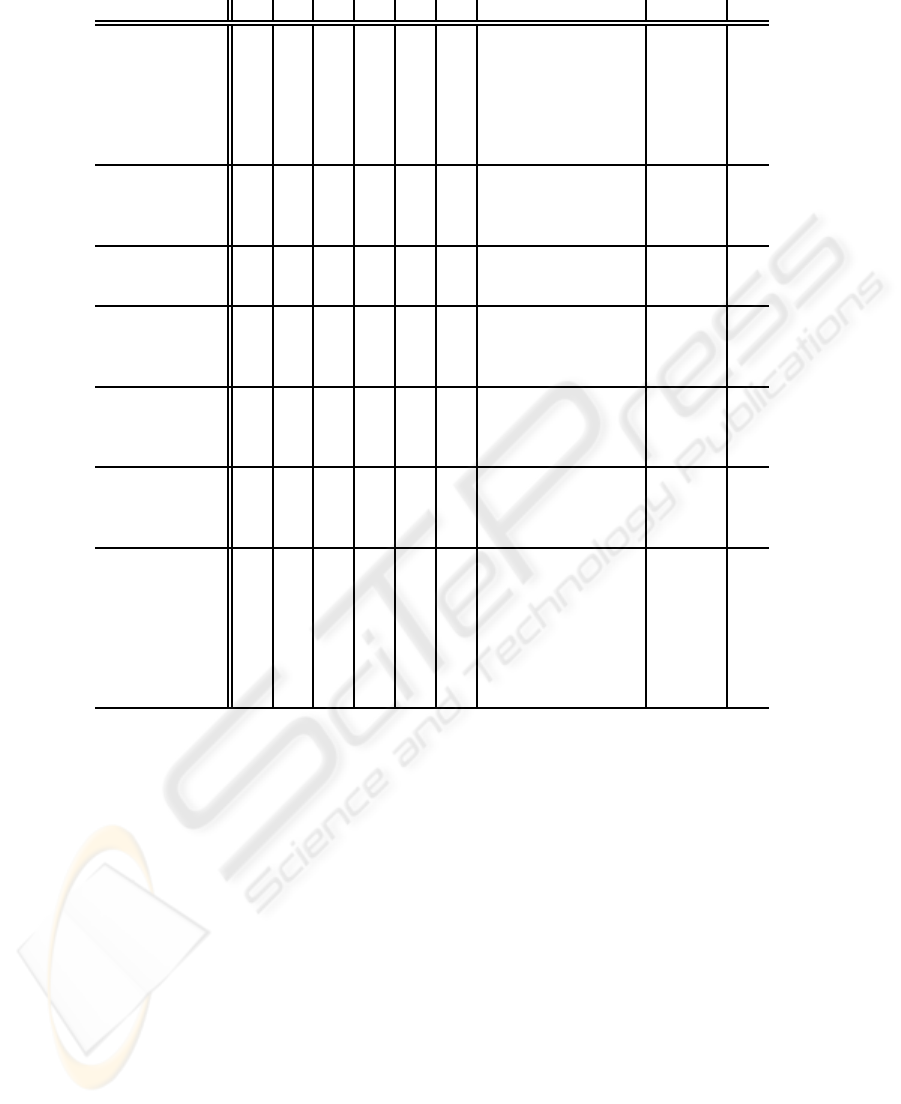
Table 1: Table of internal states and task states of the system where ◦/• stand for a normal/active tokens.
S
0
S
1
S
2
S
3
S
4
S
′
4
S
5
S
′
5
S
′′
5
S
′′′
5
S
6
S
′
6
S
7
P
1
◦ ◦ ◦ ◦ ◦ ◦ ◦ ◦ ◦ ◦
P
2
◦ ◦
P
3
◦
P
4
◦ ◦ ◦ ◦ ◦
P
5
◦ ◦ ◦ ◦ ◦ ◦ ◦
P
6
◦ ◦ ◦ ◦ ◦ ◦ ◦ ◦ ◦ ◦ ◦
P
7
◦ ◦
P
6
• ◦ • •
P
1
◦
free ◦
P
6
U P
1
• • •
P
3
◦
free ◦
F P
3
• • • • • • •
P
1
• ◦ • • • • ◦ ◦
¬P
4
◦ ◦ ◦
free ◦ ◦ ◦
P
1
U (¬P
4
) • • • • •
¬P
3
• • • •
P
2
free
(¬P
3
)U P
2
• • • •
P
1
• • ◦
P
6
◦
free
◦
P
1
U P
6
• •
¬P
4
◦ ◦ ◦ ◦ ◦ ◦ ◦ ◦
P
5
◦ ◦ ◦ ◦ ◦ ◦ ◦
Q = ¬P
4
∧ P
5
◦ ◦ ◦
¬P
3
◦ ◦ ◦ ◦ ◦ ◦ ◦ ◦ ◦ ◦ ◦ ◦
H = (¬P
3
)U Q
◦ ◦ ◦ ◦ ◦ ◦ ◦ ◦ ◦ ◦ ◦
¬P
7
◦ ◦ ◦ ◦ ◦ ◦ ◦ ◦ ◦ ◦ ◦
HS (¬P
7
)
◦ ◦ ◦ ◦ ◦ ◦ ◦ ◦ ◦ ◦ ◦ ◦ ◦
G (HS (¬P
7
))
◦ ◦ ◦ ◦ ◦ ◦ ◦ ◦ ◦ ◦ ◦ ◦ ◦
S5, place O
1
P
1
U (¬P
4
) has a token, which prohibits
firing of τ
1
and τ
3
. On the other hand, the token in
place O
2
F P
3
requests firing of τ
3
. Therefore, there is
a conflict of firing τ
3
in state S5. The only way to re-
solve this conflict is turning P
4
to ¬P
4
, which leads the
token in P
1
U (¬P
4
) to free. But the establishment of
¬H in state S5 prohibits turning P
4
to ¬P
4
by tracing
synchronized firing linkages from O G (HS (¬P
7
)). As
a result, this conflict cannot be resolved unless ¬H
turns to H.
5.3 Derivation of Control Rules
The above modifications on transition diagrams can
be translated into control actions on the extended Petri
net systems. The removal of terminal states becomes
(ii.1’) prohibit the firing of transitions just before
(leading to) the removed states.
The removal of terminal (strong) components is also
translated into the following:
(ii.2’) prohibit the firing of transitions just before
(leading to) the removed components.
It should be noted that we need supplementary
control actions over weakly correct systems for mak-
ing their behavior correct. More precisely, by refer-
ring to conditions (d.1) and (d.2) in Theorem 2, we
need the following operations:
(d.1’) if we arrive at a state where a task of the form
O
i
F A is present, then we must eventually (surely
in the future) arrive at a state where A is realized.
(d.2’) if we come to a state where O
i
(¬(AU B)) is
present, then we must eventually arrive at a state
where ¬A holds by going through states at which
B is not the case.
5.4 Decentralized Governability
In the above control operations, we have to consider
the decentralized nature of systems, i.e., each agent
ANALYZING DECENTRALIZED GOVERNABILITY OF BUSINESS PROCESSES BY EXTENDED PETRI NETS
AND MODAL LOGICS
35

τ1
τ2
τ4
τ5
τ6
τ7
P2
P1
P3
P4
P5
P6
P7
O2FP3
O2G(HS( P7))
HS( P7)
(HS( P7))
H
P7
H
P7
H
P7
H
P7
P3
P3
free
P1
P1
or
Target System
HS( P7)
(HS( P7))
P4
P4
O1(P1U P4)
free
τ3
Figure 9: Detection of the conflict at τ
3
between tasks
O
2
F P
3
and O
1
(P
1
U ¬P
4
) where the latter task is trapped
by O
2
G (HS (¬P
7
)).
having its own territory over which it has control.
Namely, we should set the following:
Condition (System Decentralization). Each prohi-
bition of firing of a transition (ii.1’) or (ii.2’) must be
caused by a task that is given to an agent whose terri-
tory includes this transition.
Thus, all the prohibition operations along with the
course of deriving a weakly correct system should
be subject to this condition. It should be noted that
there may be various ways of deriving weakly correct
systems, and only a portion of them may satisfy the
above condition. Hence, it is not easy to verify the
following property of an arbitrarily given decentral-
ized system.
Definition 4 (Decentralized Governability). A
system is called “decentralizedly controllable” if
there exists a sequence of operations (ii.1’) and (ii.2’)
in which all the prohibitions of transition firing are in
accordance with the above condition on system de-
centralization.
6 CONCLUSIONS
We have introduced the notions of decentralized gov-
ernance of event-driven processes, their behavioral
and structural correctness, and centralized and de-
centralized control for attaining correct behavior, as
well as that of decentralized governability. Also the
method of deriving correct behavioral processes is
shown. The basic framework we adopted was tempo-
ral and deontic logical analyses of process behavior
and Petri net representations of process structures.
The hierarchical decomposition of tasks eluci-
dates the governance (control) structure of tasks over
the event-driven process described by Petri net sys-
tems. The control flows descend the hierarchy, while
the flows of information reporting the changes of ob-
ject systems ascend the hierarchy. These flows go
along the fire synchronization arcs. Also the conflicts
between the control flows are elucidated. These anal-
yses and methods are expected as a basis for treating
complex business processes that are subject to high
reliability and credibility under complicated decen-
tralized governance structures.
REFERENCES
Blackburn, P. et al., editors (2006). Handbook of Modal
Logic. Elsevier.
Harary, F. et al. (1965). Structural Models: An Introduction
to the Theory of Directed Graphs. J. Wiley.
Hu, Z. and Shatz, S. M. (2004). Mapping UML diagrams to
a Petri net notation for system simulation. Proc. of the
16th Int. Conf. on Software Engineering and Knowl-
edge Engineering (SEKE), pages 213–219.
Hughes, G. H. and Cresswell, M. J. (1968). An Introduction
of Modal Logic. Methuen.
Karatkevich, A. (2007). Dynamic Analysis of Petri
Net-Based Discrete systems, volume LINCIS356.
Springer-Verlag.
Katai, O. (1981). Completeness and expressive power of
nexttime temporal logical system by semantic tableau
method. Rapport de Recherche INRIA, 109.
Katai, O. and Iwai, S. (1983). A design method for
concurrent systems based on step diagram and tense
logic under incompletely specified design criteria
(in Japanese). Systems, Control and Information,
27(6):31–40.
Nute, A. L. D., editor (2004). Deontic Logic in Computer
Science, LNAI3056. Springer-Verlag.
Peterson, J. L. (1981). Petri Net Theory and the Modeling
of Systems. Prentice Hall.
Reisig, W. (1982). Petri Nets. Springer-Verlag.
Rescher, N. and Urquhart, A. (1971). Temporal Logic.
Springer-Verlag.
Saldhana, J. and Shatz, S. M. (2000). UML diagrams to
object Petri net models: An approach for modeling
and analysis. Proc. of the Int. Conf. on Software En-
gineering and Knowledge Engineering (SEKE), pages
103–110.
ICE-B 2008 - International Conference on e-Business
36
