
BUSINESS PROCESSES MANAGEMENT USING PROCESS
ALGEBRA AND RELATIONAL DATABASE MODEL
Kelly Rosa Braghetto, Jo
˜
ao Eduardo Ferreira
Department of Computer Science, University of S
˜
ao Paulo, Rua do Mat
˜
ao 1010, 05508-090 S
˜
ao Paulo, Brazil
Calton Pu
College of Computing, Georgia Institute of Technology, Atlantic Drive 801, 30332-0280 Atlanta, U.S.A.
Keywords:
Business Process Management, Workflows, Process Algebra, Relational Databases.
Abstract:
Integrating information systems with tools that manage workflows and business processes is not always
a simple task. This difficulty becomes more accentuated when the execution control assumes countless
business processes. This work presents NavigationPlanTool (NPTool), a tool to control the execution of
business processes that can be easily integrated into the information systems. NPTool is supported by
Navigation Plan Definition Language (NPDL), a language for business processes specification that uses pro-
cess algebra as formal foundation. NPTool implements the NPDL language as a SQL extension and offers
two other important services: processes instantiation and process instances execution monitor. This paper
describes the NPTool showing how the process algebra features combined with a relational database model
can be used to provide a scalable and reliable control in the execution of business processes.
1 INTRODUCTION
Business Processes Management (BPM) involves
methods, techniques and tools to support the project,
the execution, the management and the operational
analysis of business processes (Leymann et al., 2002).
While the traditional definitions of workflow place
emphasis on the execution of operational processes,
BPM also gives support to the diagnosis phase, al-
lowing the processes to be analyzed in order to detect
flaws and possible improvements to the project.
In this context, associating formal frameworks
with the process project phase is valuable since they
provide non-ambiguous models, improve the diagno-
sis capability and enable a reliable execution control
of the process.
Although there are a number of tools based on
formal frameworks directed to the management of
workflows and business processes, integrating these
tools with other applications isn’t always easy. Some
of these tools are exclusively developed for mod-
eling and simulation of processes, as occurs in
CPN/Tools (Beaudouin-lafon et al., 2000). In other
cases, the tools effectively carry out the execution
control of business processes, but they do not pro-
vide mechanisms that allow them to be easily used
within the information systems that manage business
processes.
This work presents the NavigationPlanTool
(NPTool), a tool that offers mechanisms for the repre-
sentation and execution control of business processes
supported by a process algebra formalism (Fokkink,
2000). NPTool uses the Navigation Plan Defini-
tion Language (NPDL) (Braghetto et al., 2007) and
a relational database to specify business processes
and to control their instantiations and executions.
NPTool implements NPDL as an extension of SQL;
this implementation allows an easy integration with
traditional information systems, which generally al-
ready have mechanisms that facilitate the access to
RDBMSs. The storage of the processes data in a rela-
tional database adds scalability to the execution con-
trol provided by NPTool. Moreover, the processes
definitions can be reused in different applications. In
this context, the database maintained by NPTool can
be viewed as a common repository of processes.
Section 2 presents a summary of the related works
and the reasoning behind the use of NPDL. Sec-
tion 3 describes the services offered by the Naviga-
tionPlanTool; in particular, Section 3.1 describes the
323
Rosa Braghetto K., Eduardo Ferreira J. and Pu C. (2008).
BUSINESS PROCESSES MANAGEMENT USING PROCESS ALGEBRA AND RELATIONAL DATABASE MODEL.
In Proceedings of the International Conference on e-Business, pages 323-333
DOI: 10.5220/0001908903230333
Copyright
c
SciTePress

data structures in the relational database model to
represent the processes, and Section 3.2 explains the
mechanism for execution control. Using a real appli-
cation as example, Section 4 illustrates the execution
control applied to an instance of a process. Finally,
Section 5 discusses the contributions of this work.
2 RELATED WORK
Management technologies for business processes
were developed to meet the following needs: (1) to
promote the separation between the specification of
the process and its implementation; and (2) to take
away from the applications the responsibility of the
execution control of business processes. Among the
various existing languages to define business pro-
cesses, it is not easy to see a formal pattern as a rep-
resentation basis, one that is capable of expressing in
a non-ambiguous way the semantics associated to the
existing constructions in these languages. The for-
malisms regarded as natural candidates for this role
are the Petri nets and the process algebras. Works
such as (Aalst, 1998), (Puhlmann and Weske, 2005)
describe the use of these formalisms in the specifica-
tion of business processes.
The Yet Another Workflow Language
(YAWL) (Aalst and Hofstede, 2005) is the most
well succeeded approach for business process specifi-
cation based on Petri nets. It was developed intending
to provide means for defining all the original control-
flow patterns described in (Aalst et al., 2003). Also
with the intention of representing business processes
with a formal basis, Navigation Plan Definition
Language (NPDL) (Braghetto et al., 2007) was
created. NPDL is based on the concept of navigation
plan of RiverFish architecture (Ferreira et al., 2005)
as well as in the operators of ACP (Fokkink, 2000), a
member of the family of process algebras. The navi-
gation plan was formalized in (Ferreira et al., 2006)
as a set of all business processes demanded from
an application in order to achieve business goals.
Like in processes algebras, processes in NPDL are
defined by algebraic expressions. The expression of
a process is built based on NPDL operators and steps
(atomic actions or processes); the operators indicate
the execution order of the steps. For completeness,
we will provide an overview of NPDL operators.
2.1 NPDL Operators
The basic control-flow patterns described in (Aalst
et al., 2003) can be easily represented with three basic
operators of NPDL:
•Sequential Composition (“.”). the process term
A.B means that the activity B will be enabled for ex-
ecution after the completion of the activity A. An ac-
tivity can be an atomic action or a subprocess;
• Alternative Composition (“+”). the process
term A + B means that initially both activities A and
B will be enabled for execution, but only one of them
can be executed;
• Parallel Composition (“||”). the process term
A||B means that the activities A and B can be executed
parallelly.
These basic operators were directly extracted from
ACP (Algebra of Communicating Processes) and have
their semantics formally defined by a set of transition
rules that will be presented in the Section 3.2. In or-
der to represent all control-flow patterns identified by
Aalst et al in (Aalst et al., 2003), the NPDL was im-
proved with additional operators:
• Interleaved Parallel Composition (“|∗”). the
process term A|∗B means that the activities A and B
can be executed in any order (e.g., A.B+B.A), but not
in parallel;
• Multi Merge Composition (“&”). the process
term A&B means that the activity B will be enabled
for execution after the completion of each thread of
control of activity A;
•Discriminator Composition (“∧”). the process
term A ∧B means that the activity B will be enabled
for execution after the completion of the first thread
of control of activity A;
• Unlimited Repetition (“?∗”). the process term
A?∗ means that the activity A can be executed an un-
restricted number of times;
• Number Limited Repetition (“?n”, where n
is a positive integer number). the process term A?5
means that the activity A must be executed five times;
•Function Limited Repetition (“? f ”, where f is
a function that returns a positive integer number). the
process term A? f
1
means that the activity A must be
executed the number of times calculated by function
f
1
at execution time;
• Conditional Execution (“%r”, where r is a
rule, e.g. a boolean function). the process term %r
1
A
means that the activity A will be enabled for execution
if the return value of the rule r
1
is true at execution
time;
• Negative Conditional Execution (“%!r”,
where r is a rule, e.g. a boolean function). the process
term %!r
1
A means that the activity A will be enabled
for execution if the return value of the rule r
1
is false
at execution time.
Providing more details about NPDL is beyond the
scope of this paper; the definition of the language
and the specification in NPDL of each one of the 20
ICE-B 2008 - International Conference on e-Business
324

control-flow patterns described in (Aalst et al., 2003)
can be seen in (Braghetto et al., 2007).
3 NavigationPlanTool
NavigationPlanTool (NPTool) provides methods for
storing actions and processes in a relational database
and for controlling the instantiation and execution of
these processes. The tool offers operations like cre-
ation/removal of instances and services for monitor-
ing the navigation plan execution. These services are
also responsible for storing logs of the execution of
navigation plans in the database and for recovering
executions that have been interrupted before comple-
tion.
The programming language used in the implemen-
tation of NPTool was Java (Java 2 Platform Standard
Edition - J2SE 5.0). NPTool extends JDBC API -
Java DataBase Conectivity Application Programming
Interface. JDBC enables Java programs to execute
SQL commands and to interact with databases that are
compatible with SQL standard. The usage of JDBC
turns NPTool into a RDBMS independent tool. Since
it was developed as a library of functions, the NPTool
can be easily integrated into other Java applications.
NPTool is composed of three services:
• NPDL Interpreter. receives an input command
and makes the lexical, syntactic and semantical anal-
ysis. There are two possible situations: (1) the com-
mand is a NPDL valid command, and (2) the com-
mand is not a NPDL valid command. In the for-
mer case, the interpreter will translate the command
to pure SQL commands before the submission to the
RDBMS. In the latter case, the command will be
directly passed to the RDBMS. The translated SQL
commands will be executed over a relational database
environment whose tables are created by the inter-
preter to store processes, actions and instances data;
• Process Instantiation Service. provides func-
tions for creating process instances. A process in-
stance represents a request to a specific process. All
the instance data, as well as process definition data
associated with the instance, are stored in a database;
• Process Instance Execution Monitor. is re-
sponsible for linking a process instance to its execu-
tion data (navigation plan). This service contains the
functions that control the execution of the navigation
plan of a process instance.
3.1 The Relational Data Structures
Created by NPDL Interpreter
The relational data model does not have appropriate
structures for representing processes and, therefore,
it requires an additional data structure to achieve this
task.
In (Braghetto et al., 2007), the NPDL syntax was
defined as an extension of the SQL syntax. The main
goal of implementing NPDL as a SQL extension was
to enable a RDBMS to create and handle business
processes, providing to information systems an easy
access to these features. The data structure kept stored
in a database by NPTool is represented in the extended
entity-relationship diagram shown in Figure 1. The
diagram shows the data structures needed for repre-
senting business processes and for controlling their
instantiations and executions.
In NPDL, the navigation plan of a process
is defined by an algebraic expression formed by
steps composed by operators that indicate the ex-
ecution order of these steps. The relationship-
set NAVIGATION PLAN REL between the entities-set
PROCESS and STEP represents this definition. The
specialization of STEP is total and disjoint, i.e., each
entity in STEP is a process, or an action, or an op-
erator, or a rule, or a function or a number. As
described in Section 2.1, rules are always associ-
ated with the operators “%” and “%!”, whereas func-
tions and numbers are associated with operator “?”.
The entity-set PROCESS INSTANCE and the relation-
ship INSTANCE LOG REL are associated with the in-
stantiation and control of process execution. An entity
of PROCESS INSTANCE is always associated with an
entity of PROCESS, as the relationship PROCESS INS-
TANCE REL shows; an instance represents a process
request. The relationship INSTANCE LOG REL repre-
sents the data related to execution status of the steps
that compose the navigation plan of a process in-
stance. Each entity of INSTANCE LOG REL represents
the execution of a step in a specific process instance.
In Section 3.2, the implementation of the service
Process Instance Execution Monitor will be detailed
to show how process algebra properties and this re-
lational database model were used for developing a
scalable and reliable engine that controls the business
processes execution.
3.2 The Execution Control of Business
Processes in NPTool
When an execution of a process instance is started,
the navigation plan associated with the instance is re-
covered from database. According to the algebraic
BUSINESS PROCESSES MANAGEMENT USING PROCESS ALGEBRA AND RELATIONAL DATABASE MODEL
325
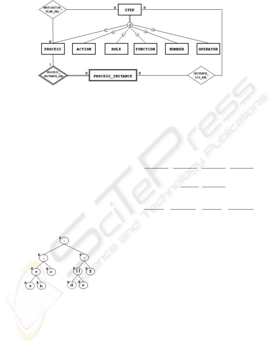
Figure 1: Extended entity-relationship diagram of process data.
expression that represents the navigation plan, an ex-
pression tree of the instance is built. Expression trees
are used in the execution monitor service to determine
the execution order of the steps in the navigation plan.
In this work, the expression tree of a process instance
was called navigation tree. A navigation tree node can
represent one of these three elements: a NPDL opera-
tor, an action or a process. A navigation tree is a com-
plete binary tree; its internal nodes represent binary
operators of NPDL, whereas its leaf nodes represent
actions or processes. As the navigation tree nodes rep-
resent the possible execution steps, an important at-
tribute of a node is its current status. A node, in a spe-
cific point of the instance execution, can be in one of
the following states: not started (N), started (S), fin-
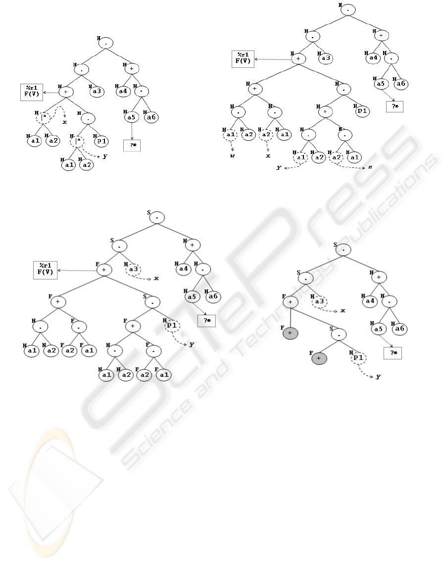
ished (F) or canceled (C). The Figure 2 shows an hy-
pothetical example of one of the possible navigation
tree for an instance of process P = (a + b).c.(dke). f .
Figure 2: Navigation tree of an instance of process
P = (a + b).c.(dke). f .
After creating the navigation tree, the execution
monitor recovers the current state of the instance exe-
cution by consulting the execution instances log, that
is stored in the database. This operation only is done
for instances that have already started their execution,
but have not finished it yet. When an instance execu-
tion is started, all nodes in its navigation tree will have
the current status not started. If the instance execu-
tion have already been started in a previous execution
of the monitor service, there will be records related to
the instance in the log and they must be loaded to the
navigation tree. This is made by updating the status
of the tree nodes associated with the steps indicated as
started, finished or canceled in the log. Each step per-
formed in the navigation plan of an instance results in
the insertion or update of a record in the log.
x
v
−→
√
x + y
v
−→
√
x
v
−→ x
0
x + y
v
−→ x
0
y
v
−→
√
x + y
v
−→
√
y
v
−→ y
0
x + y
v
−→ y
0
(1)
x
v
−→
√
x.y
v
−→ y
x
v
−→ x
0
x.y
v
−→ x
0
.y
(2)
x
v
−→
√
xky
v
−→ y
x
v
−→ x
0
xky
v
−→ x
0
ky
y
v
−→
√
xky
v
−→ x
y
v
−→ y
0
xky
v
−→ xky
0
(3)
Figure 3: Transition rules for basic operators of process al-
gebra. The variables x and y in the rules range over basic
process terms, while v ranges over the set of atomic actions.
The “navigation” through the tree of an instance
determines the execution order of the steps of this
instance. The algorithms of the monitor service of
NPTool use the semantics of NPDL operators and the
transition rules of process algebra to visit a naviga-
tion tree. Figure 3(1,2,3) shows the transition rules
extracted from (Fokkink, 2000) that define the oper-
ational semantics of terms of basic process algebra
and ACP. The operational semantics of a language de-
scribes how a valid sentence must be interpreted in
sequential steps. Figures 4 to 6 show how the transi-
tion rules are applied on the navigation tree branches
to guarantee that the instance status, after starting or
finishing the execution of an action, will be consistent
with the behavior specified by the algebraic expres-
sion of the process associated with the instance.
The four rules in Figure 3(1) states that the pro-
cess defined by the term x + y terminates successfully
after executing x or y. Figure 4 shows how the alter-
ICE-B 2008 - International Conference on e-Business
326
Figure 4: State transitions for a branch rooted at an operator
of alternative composition.
native composition operator (“+”) is treated in a nav-
igation tree branch. As in figures 7 to 14, the nodes
delimited by an ellipse with dashed line indicate the
actions that are enabled for execution in the current
instance state represented by the tree. The labeled ar-
rows signalize the start or the end of the execution of
an action
1
. So, S(a) signalizes the start of the action
a, while F(a) signalizes the end of the same action.
The start or finish of the execution of an action in
an instance modifies the status of a leaf node in its
navigation tree. Each modification in the status of a
leaf node in a navigation tree requires the update of
status of its predecessor nodes. To enable this opera-
tion, each node keeps a pointer to its parent node, be-
sides the pointers to the left child and the right child
nodes. The status node configuration in a navigation
tree determines the current state of the instance; thus,
a change in the instance state generates a new set of
actions currently enabled for execution. The status of
a node that represents an alternative composition op-
erator is specified by the status of its child nodes in
the following way:
• Started : if the left or the right child has status
started ;
• Finished : if the left or the right child has status
finished ;
• Canceled : if the left and the right child has sta-
tus canceled.
Figure 5: State transitions for a branch rooted at an operator
of sequential composition.
In Figure 3(2), the rules state that the process rep-
1
In NPTool, the actions of a process may not have an
instantaneous execution, i.e., the execution can be distin-
guished by a start event and by an ending event.
resented by x.y executes first x and, after x have been
finished successfully, it starts the execution of y. Fig-
ure 5 shows the possible state changes in a branch
rooted at a sequential composition (“.”) operator.
The status of a node with a sequential composition
operator is specified by the status of its child nodes in
the following way:
• Started : if the left child has status started or if
the left child has the status finished and the right child
has status started. The right child will never have sta-
tus started while the left child does not have status
finished ;
• Finished : if the left and the right child has sta-
tus finished ;
• Canceled : if the left and/or the right child has
status canceled.
The process term xky indicates that the terms x and
y will be executed parallelly, i.e., it is possible to ex-
ecute an initial transition of x (x
v
−→
√
or x
v
−→ x
0
)
or a initial transition of y. This behavior is formally
specified by the rules in Figure 3(3). The set of all
the possible states originated by an expression involv-
ing the parallel composition (“k”) operator is large, as
Figure 6 shows. The status of a node that represents
the parallel composition operator is specified by the
status of its child nodes in the following way:
• Started : if the left or the right child has status
started ;
• Finished : if the left and the right child has sta-
tus finished ;
• Canceled : if the left and/or the right child has
status canceled.
The conditional execution, negative conditional
execution, unlimited repetition, number limited rep-
etition and function limited repetition operators are
not treated as nodes in the navigation tree. They are
treated as attributes of nodes, since they influence the
execution of the complete branch rooted at the node
with which they are associated. If a node have a rule
or a function associated with it, then it is necessary
to execute this rule or function before “visiting” the
node in the navigation algorithm. The execution of
the rule or function, like in the case of atomic ac-
tions, is a responsibility of the applications that use
the NPTool. When an action or a process term is
delimited by some of the two conditional execution
operators, the rule that conditionates the execution is
attributed to the node that represents the delimited ac-
tion or to the root node of the delimited process term.
In the example of Figure 7(a), the execution of ac-
tion a is conditioned by the return value true of rule
r
1
, while the execution of b is conditioned by the re-
turn value false. In this example, the return value of r
1
was true; so, after finishing the execution of r
1
, only
BUSINESS PROCESSES MANAGEMENT USING PROCESS ALGEBRA AND RELATIONAL DATABASE MODEL
327
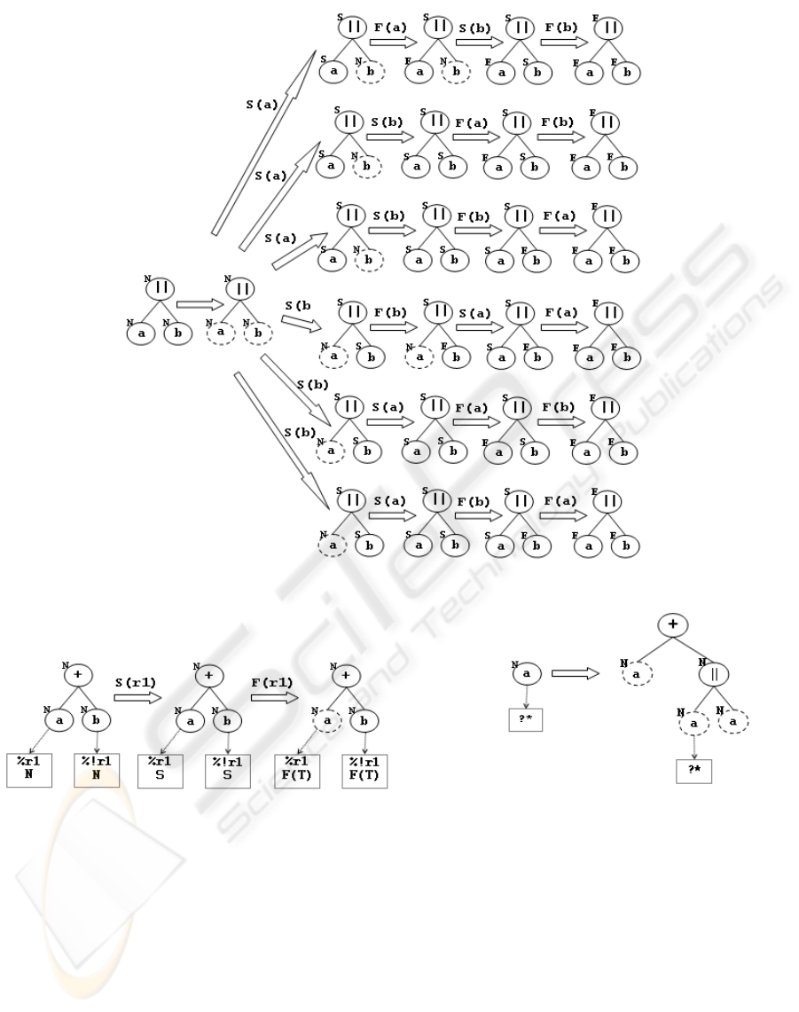
Figure 6: State transitions for a branch rooted at an operator of parallel composition.
(a) (b)
Figure 7: Treatment of (a) node associated with rules or functions and (b) nodes with unlimited repetition.
the action a was enabled to be executed.
In the case of repetitive actions or process terms,
the node that represents the action or term is labeled as
repetitive, and if this repetition is limited by a number
or a function, this number or function will be associ-
ated with the node. Figure 7(b) shows how a repeti-
tive node is treated by “expanding” it in an equivalent
branch.
The inspection of a navigation tree in order to get
enabled steps to execution in an instance is also con-
trolled by the transition rules expressed in Figure 3;
the rules are used to determine how the nodes of the
tree should be visited. The execution monitor starts
to visit the navigation tree from its root node. Ac-
cordingly the current status of the tree nodes, the nav-
igation returns a set of steps currently enabled to be
executed in the instance.
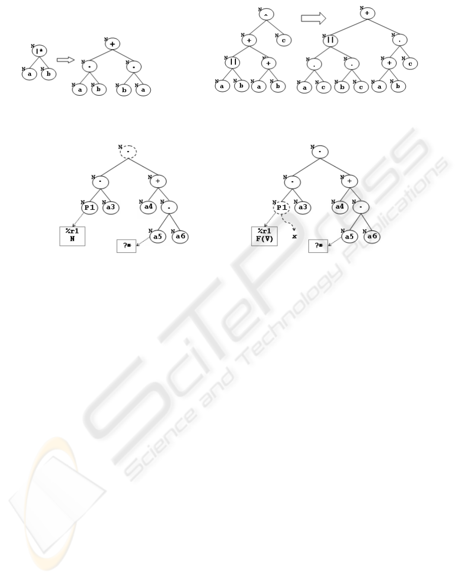
Only the basic operators of NPDL are kept in the
navigation tree. The other operators are treated by
a mapping algorithm that removes them of the nav-
igation tree, replacing them by an equivalent branch
containing only basic operators. Figures 8 and 9 show
how nodes rooted at non-basic NPDL operators in the
navigation tree can be replaced by other equivalent
ICE-B 2008 - International Conference on e-Business
328

Figure 8: Treatment of a branch rooted at a multi merge
composition operator.
branches.
Processes that involve in their definition a refer-
ence to other processes are treated by a simple substi-
tution. The navigation tree for the referred process is
created and “connected” to the navigation tree of the
instance, replacing the node that represents the pro-
cess. After the substitution of the process node by the
tree that represents it, the algorithm for obtaining en-
abled steps is applied on the root node of the referred
process.
The execution of an instance is considered suc-
cessfully complete when the status of the root node of
its navigation tree is set to finished.
4 EXAMPLE OF EXECUTION
CONTROL
This section illustrates a simulated execution of a pro-
cess instance. It shows how works the navigation that
gets the enabled steps and updates the state of the nav-
igation tree. The process used as example is a simpli-
fied version of a system developed for controlling the
acquisition of items to a library collection.
Consider the set of rules and the set of actions
belonging to the acquisition system that are defined,
respectively, as R = {r
1
} and A = {a
1
, a
2
, a
3
, a
4
, a
5
},
such that:
• r
1
checks the completeness of data from acqui-
sition order and the availability of the budget for pur-
chasing;
• a
1
sorts the order items according to some prior-
ity;
• a
2
gathers the prices of the order items;
• a
3
liberates the order for purchasing;
• a
4
registers the purchase receiving;
• a
5
registers a problem with the purchase.
The acquisition system can be specified by the
process P defined in NPDL by the commands:
SET P1 = a1 |* a2 + (a1 |* a2).P1;
SET P = %r1 P1 . a3 . (a4 + a5?* . a4);
The check step of order data is treated as a rule (in
the case, r
1
). Thus, the execution of the activities in-
volved in the acquisition system will only be enabled
if the order data is valid and there is available bud-
get for the purchase. The subprocess P
1
encapsulates
the actions of sorting items (a
1
) and gathering items
price (a
2
) . The actions are composed by the operator
“|∗”, that indicates that they can be executed in any
order, but not in parallel. Moreover, P
1
was defined
in a recursive way. This indicates that these actions
can be repeated an unrestricted number of times be-
fore the liberation of the order for purchasing. After
the liberation of the order (action a
3
), it is possible
that problems occur in the purchase. These problems
are registered in the acquisition process by the action
a
5
. The repetition operator “?∗” was used associated
with a
5
, to represent the possibility of occurring more
than one problem during the purchase.
The initial navigation tree of an instance of acqui-
sition process is represented in Figure 10(a). Each
node has, at the upper left side, a character that indi-
cates one of the following states: “N” (not started),
“S” (started) and “F” (finished). It is important to no-
tice that, associated with the node that represents the
process P
1
in the tree, exists the rule r
1
. Such as the
tree nodes, a rule has a status too. Associated with the
node representing action a
5
, exists the operator “?∗”,
that indicates that the action can have its execution
repeated.
In the beginning of the execution, the tree is vis-
ited starting on its root node (distinguished by a
dashed line in Figure 10(a)). While the navigation
algorithm is visiting the tree nodes, it comes across
the rule r
1
and it adds the rule in the set of currently
enabled steps to execution. Since the execution of the
other steps depends on the execution of step condi-
tioned by r
1
, no other step can be executed at first.
Considering now that r
1
have been executed and
its return value was true, the algorithm for getting the
currently enabled steps is applied on the node associ-
ated with r
1
in the tree and finds the node x in Fig-
ure 10(b). The node x represents the process P
1
and,
as explained previously, it needs to be expanded by
replacing the node by its navigation tree. Figure 11(a)
shows the tree after the substitution.
Continuing the visitation to the tree nodes, the al-
BUSINESS PROCESSES MANAGEMENT USING PROCESS ALGEBRA AND RELATIONAL DATABASE MODEL
329
(a) (b)
Figure 9: Treatment of a branch rooted at the operators (a) interleaved parallel and (b) discriminator composition.
(a) (b)
Figure 10: (a) Initial state of the tree for an instance of acquisition process. (b) Tree after the execution of the rule r
1
.
gorithm detects the existence of the operator “|∗” in
two different places in the tree (nodes x and y in Fig-
ure 11(a)). Since the operator “|∗” is not a NPDL
basic operator, it requires a special treatment.
In NPDL, a process term like a|∗b is equivalent
to a.b + b.a. Figure 11(b) shows the navigation tree
after mapping the operators “|∗”. After the map-
ping, the visitation algorithm is able to identify the
currently enabled steps to execution. As the distin-
guished nodes in Figure 11(b) shows, there are two
enabled steps to execution in the navigation tree: ac-
tions a
1
and a
2
.
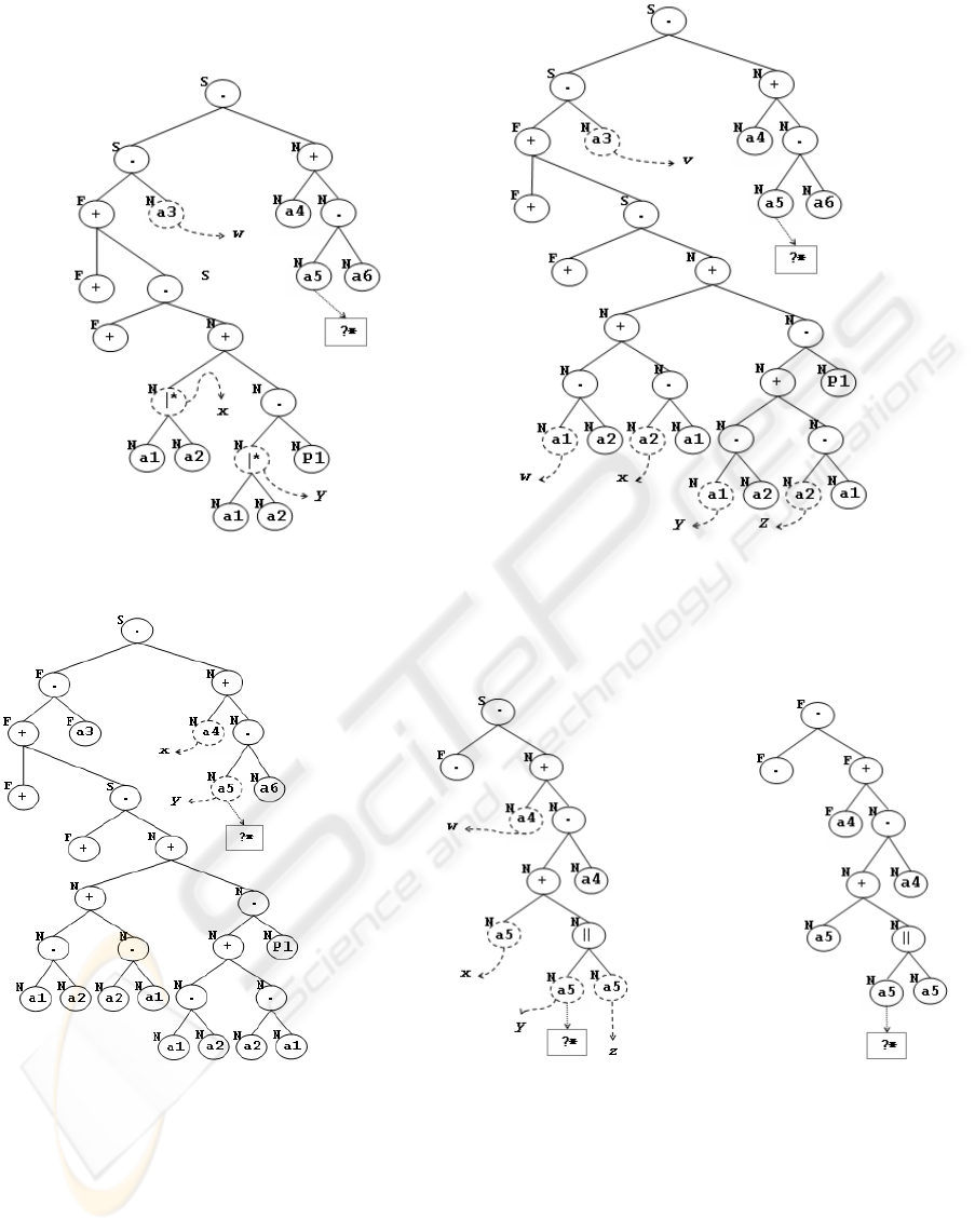
Consider that, after the execution of r
1
, the action
a
2
have been executed, and the algorithm for propa-
gating the status update through the tree nodes is ap-
plied on the nodes x and z of Figure 11(b). In the
resulted tree, only the action a
1
is enabled to execu-
tion; Figure 12(a) shows the tree after the execution
of a
1
.
In a navigation tree, branches rooted at a node
whose status have already been defined as finished
and which do not have enabled steps to execution can
be removed from the tree. The goal of this removal is
the optimization of the main memory occupied by the
storage of the trees. Figure 12(b) illustrates the tree
resulted by the removal of the inaccessible branches
of the tree in Figure 12(a); the nodes distinguished by
the background color gray are the nodes that had their
children removed.
The navigation for getting the currently enabled
steps to execution detects the node y in Figure 12(b),
which once more represents the process P
1
. The node
is replaced by the navigation tree of process P
1
, result-
ing the tree in Figure 13(a). In the tree in Figure 13(a),
the nodes x and y represents the operators “|∗”, which
must be mapped to basic operators, resulting the tree
in Figure 13(b). In the tree in Figure 13(b), the en-
abled steps are the actions a
1
(nodes w and y), a
2
(nodes x and z) and a
3
(node v). If the chosen step
for execution is the action a
3
, the application of the
algorithm for propagating the status update through
the tree nodes over the node v in Figure 13(b) results
in the tree in Figure 14(a).
When the algorithm of navigation finds the node
y in the tree in Figure 14(a), it will apply the map-
ping of the operator “?∗” associated with the action
a
5
, resulting the tree in Figure 14(b). In this tree, the
currently enabled steps to execution are the actions a
4
and a
5
. The tree in Figure 14(c) is obtained by execut-
ing the action a
4
and applying algorithm for propagat-
ing the status update over the node w in Figure 14(b).
The root node of the tree in Figure 14(c) has the sta-
tus finished, which indicates that the execution of the
process instance was terminated successfully.
ICE-B 2008 - International Conference on e-Business
330
(a) (b)
Figure 11: (a) Navigation tree after the substitution of P
1
and, next, (b) after the substitution of operators “|∗”.
(a) (b)
Figure 12: Navigation tree (a) after the execution of actions a
2
and a
1
, and (b) after the removal of inaccessible branches.
5 CONCLUSIONS
NavigationPlanTool is a framework that uses NPDL
and a relational database model to specify business
processes and control their instantiations and execu-
tions. The NPDL language is based on the concept of
navigation plan of the RiverFish architecture as well
as in the operators of processes algebra.
The simplicity of the relational database model
(used by NPTool for the storage of processes, in-
stances and its executions) is consequence of the
adoption of processes algebra as formal basis, due
to its algebraic and textual form. Albeit simple, this
model has proved to be quite flexible, since it allows
the enrichment of the expressiveness of NPDL (by in-
cluding new operators in the language) without caus-
ing impact to the data structure. This model also
allows us to make reuse of the processes definition
between different applications that use the NPTool,
as it can be viewed as a common repository of pro-
cesses. Moreover, the compositional characteristic of
processes algebra makes the composition of great pro-
cesses from smaller ones possible. This constitutes an
important aspect for business processes, in which the
reuse of definitions is a common occurrence.
The implementation of NPDL as an extension of
the SQL language provided by NavigationPlanTool
allows its easy integration to traditional information
systems, which already have mechanisms that facili-
tate the access to RDBMSs. In addition to that, the
storage of the processes definition data, instances and
its executions in a relational database makes the Nav-
BUSINESS PROCESSES MANAGEMENT USING PROCESS ALGEBRA AND RELATIONAL DATABASE MODEL
331
(a) (b)
Figure 13: Navigation tree (a) after substituting P
1
and, next, (b) after the substitution of the operators “|∗”.
(a) (b) (c)
Figure 14: Navigation tree (a) after executing action a
3
, (b) after the removal of inaccessible branches and mapping operator
“?∗”; next, (c) after executing action a
4
.
igationPlanTool a tool that can be used by informa-
tion systems that require scalable and reliable control
to execute business processes. These reliability and
scalability are assured by the use of a RDBMS.
Currently NPTool has been used in three im-
portant applications: controlling the acquisition and
lending of library items at University of S
˜
ao Paulo
(USP); managing of clinical exams in the Human
Genoma Institute at USP, and the identification of
HIV drug resistance. Details about the latter can
be seen in (Ara
´
ujo et al., 2008); the referred paper
presents an alternative for mapping of genotypic drug
resistance algorithms rules using NPDL expressions.
Our ongoing research topics include the identifi-
ICE-B 2008 - International Conference on e-Business
332

cation and reuse of control-flow patterns in business
processes, data flow management for business pro-
cesses and automated generation of NPDL expres-
sions from graphical representations.
REFERENCES
Aalst, W. (1998). The application of petri nets to workflow
management. The Journal of Circuits, Systems and
Computers, 8(1):21–66.
Aalst, W. and Hofstede, A. (2005). YAWL: Yet another
workflow language. Information Systems, 30(4):245–
275.
Aalst, W., Hofstede, A., Kiepuszewski, B., and Barros, A. P.
(2003). Workflow Patterns. Distributed and Parallel
Databases, 14(1):5–51.
Ara
´
ujo, L. V., Sabino, E. C., and Ferreira, J. E. (2008). HIV
drug resistance analysis tool based on process alge-
bra. In Proceedings of the 2008 ACM Symposium on
Applied Computing, Fortaleza, Brazil, March 16-20,
2007, pages 1358–1364. ACM.
Beaudouin-lafon, M., Mackay, W. E., Andersen, P.,
Janecek, P., Jensen, M., Lassen, M., Lund, K.,
Mortensen, K., Munck, S., Ratzer, A., Ravn, K.,
Christensen, S., and Jensen, K. (2000). CPN/Tools:
A post-WIMP interface for editing and simulating
coloured petri nets.
Braghetto, K. R., Ferreira, J. E., and Pu, C. (2007). Us-
ing control-flow patterns for specifying business pro-
cesses in cooperative environments. In Proceedings
of the 2007 ACM Symposium on Applied Computing,
Seoul, Korea, March 11-15, 2007, pages 1234–1241.
ACM.
Ferreira, J. E., Takai, O. K., Braghetto, K. R., and Pu, C.
(2006). Large scale order processing through navi-
gation plan concept. In Proceedings of the IEEE In-
ternational Conference on Services Computing, pages
297–300. IEEE Computer Society.
Ferreira, J. E., Takai, O. K., and Pu, C. (2005). Integration
of collaborative information system in internet appli-
cations using riverfish architecture. In Collaborate-
Com. IEEE.
Fokkink, W. (2000). Introduction to Process Algebra.
Springer.
Leymann, F., Roller, D., and Schmidt, M.-T. (2002). Web
services and business process management. IBM Sys-
tems Journal, 41(2):198–211.
Puhlmann, F. and Weske, M. (2005). Using the pi-calculus
for formalizing workflow patterns. In Springer, editor,
Third International Conference on Business Process
Management (BPM 2005), pages 153–168.
BUSINESS PROCESSES MANAGEMENT USING PROCESS ALGEBRA AND RELATIONAL DATABASE MODEL
333
