A PROTOTYPE FOR PRACTICAL EYE-GAZE CORRECTED
VIDEO CHAT ON GRAPHICS HARDWARE
Maarten Dumont
1
, Steven Maesen
1
, Sammy Rogmans
1,2
and Philippe Bekaert
1
1
Hasselt University – tUL – IBBT, Expertise centre for Digital Media, Wetenschapspark 2, 3590 Diepenbeek, Belgium
2
Multimedia Group, IMEC, Kapeldreef 75, 3001 Leuven, Belgium
Keywords:
Prototype, practical, video chat, eye-gaze correction, GPU, real-time.
Abstract:
We present a fully functional prototype to convincingly restore eye contact between two video chat partici-
pants, with a minimal amount of constraints. The proposed six-fold camera setup is easily integrated into the
monitor frame, and is used to interpolate an image as if its virtual camera captured the image through a trans-
parent screen. The peer user has a large freedom of movement, resulting in system specifications that enable
genuine practical usage. Our software framework thereby harnesses the powerful computational resources
inside graphics hardware, to achieve real-time performance up to 30 frames per second for 800 × 600 resolu-
tion images. Furthermore, an optimal set of finetuned parameters are presented, that optimizes the end-to-end
performance of the application, and therefore is still able to achieve high subjective visual quality.
1 INTRODUCTION
Peer-to-peer interactive video chat is becoming in-
creasingly popular, but still has some major draw-
backs which prevent a definitive breakthrough in the
common public. One of the most important reasons
is that the participant is not able to simultaneously
look at the screen and the camera, leading to the loss
of eye contact (Gemmell et al., 2000). We therefore
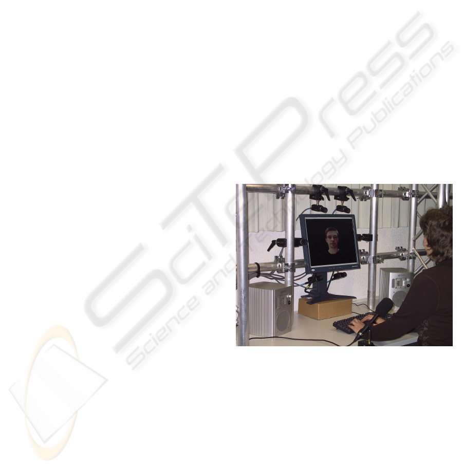
present a fully functional prototype (see Fig. 1) that
corrects the eye gaze of the peers by using multiple
cameras, solving typical problems for genuine practi-
cal usage. Previous solutions such as (Criminisi et al.,
2003) either implement their framework on commod-
ity CPUs, resulting in a very low framerate when suf-
ficient visual quality is required. On the opposite side,
solutions such as (Schreer et al., 2001; Baker et al.,
2002) involve the use of expensive dedicated hard-
ware, or have an unpractical camera setup. Others op-
timize parts of the application, such as multi-camera
video coding (Chien et al., 2003; Guo et al., 2005)
for efficient data communication and real-time view
synthesis (Yang and Pollefeys, 2003; Geys and Van
Gool, 2004; Nozick et al., 2006) on graphics hard-
ware, but neither of them integrate and optimize the
end-to-end performance for eye gaze-corrected video
chat. The end-to-end performance for camera inter-
polation is optimized in (Rogmans et al., 2008), but
they assume a rectified two-fold camera setup and no
Figure 1: Peer setup of our prototype.
illumination changes due to the use of the Middlebury
dataset (Middlebury, 2001).
Our prototype uses a practical camera setup that
can be easily integrated in the monitor frame, and its
framework harnesses the powerful computational re-
sources inside the Graphics Processing Unit (GPU)
to achieve real-time performance on commodity PCs.
Section 2 of the paper describes the system archi-
tecture in detail, which proposes the use of several
carefully selected and slightly adapted algorithms that
are appropriate for implementation on graphics hard-
ware. The end-to-end system thereby achieves both
high speed and quality with only few constraints. We
236
Dumont M., Maesen S., Rogmans S. and Bekaert P. (2008).
A PROTOTYPE FOR PRACTICAL EYE-GAZE CORRECTED VIDEO CHAT ON GRAPHICS HARDWARE.
In Proceedings of the International Conference on Signal Processing and Multimedia Applications, pages 236-243
DOI: 10.5220/0001932402360243
Copyright
c
SciTePress
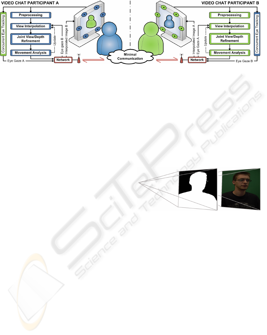
Figure 2: Data flow and overview of our system architecture.
also provide a number of GPU specific optimizations
in Section 3 to ensure real-time application perfor-
mance. Section 4 discusses the results of the proto-
type, Section 5 ultimately concludes the paper, and
Section 6 deals with future work.
2 SYSTEM ARCHITECTURE
As depicted in Fig. 2, the main functionality of our
system consists of four consecutive processing mod-
ules that are completely running on a GPU. In an ini-
tial step, images I
1
, . .. , I
N
are fetched from N cameras
C
1
, . . . ,C
N
that are closely aligned along the screen.
The first module performs lens correction and image
segmentation, as a form of preprocessing, to enhance
both the quality and speed of the consecutive view in-
terpolation.
This second module interpolates an image I
v
, as
seen with a virtual camera C
v
that is positioned behind
the screen and produces a consistent depth map Z
v
.
The image I
v
is computed as if camera C
v
captured
the image through a completely transparent screen.
However, the synthesized image still has a num-
ber of noticeable artifacts in the form of erroneous
patches and speckle noise. The third refinement mod-
ule is therefore specifically designed to tackle these
problems by detecting photometric outliers based on
the accompanying depth map.
In a final step, the depth map Z
v
is also analyzed
to dynamically adjust the system and thereby avoids
heavy constraints on the user’s movements.
Next to the main processing on graphics hardware
that synthesizes I
v
, the camera C
v
needs to be cor-
rectly positioned to restore eye contact between the
participants. An eye tracking module thereby concur-
rently runs on CPU and determines the user’s eye po-
sition that will be used for correct placement of the
virtual camera at the other peer.
By sending the eye coordinates to the other peer,
the input images I
1
, . . . , I
N
do not have to be sent over
the network, but can be processed at the local peer.
This results in a minimum amount of required data
communication – i.e. the eye coordinates and the in-
terpolated image – between the two participants.
2.1 Preprocessing
Camera lenses, certainly when targeting the low-
budget range, induce a radial distortion that is best
corrected. Our system relies on the use of the Brown-
Conrady distortion model (Brown, 1966) to easily
undistort the input images pixel-based on the GPU.
Figure 3: The preprocessing module segments the input
camera image.
Each input image I
i
with i ∈ {1, . . . , N} is conse-
quently segmented into a binary foreground silhou-
ette S
i
(see Fig. 3), to allow the consecutive view in-
terpolation to adequately lever the speed and quality
of the synthesis process. Two methods of segmenta-
tion are supported; Greenscreening according to (1),
where R
I
i
, G
I
i
and B
I
i
are the red, green and blue com-
ponents of I
i
. For clarity the pixel location (x, y) has
been omitted.
S
i
=
1 : G
I
i
> τ
g
· (R
I
i
+ G
I
i
+ B
I
i
)
0 : G
I
i
≤ τ
g
· (R
I
i
+ G
I
i
+ B
I
i
)
(1)
The second method is able to subtract a real-life back-
ground (Magnor et al., 2005) according to (2), where
I
B
i
is the static background picture and τ
g
, τ
f
, τ
b
, τ
a
are experimentally determined thresholds which are
subjected to parameter finetuning. For shadow re-
moval, the cosine of the angle
d
I
i
I
B
i
between the color
component vectors of the image pixel I
i
(x, y) and the
static background pixel I
B
i
(x, y) is determined. As a
A PROTOTYPE FOR PRACTICAL EYE-GAZE CORRECTED VIDEO CHAT ON GRAPHICS HARDWARE
237
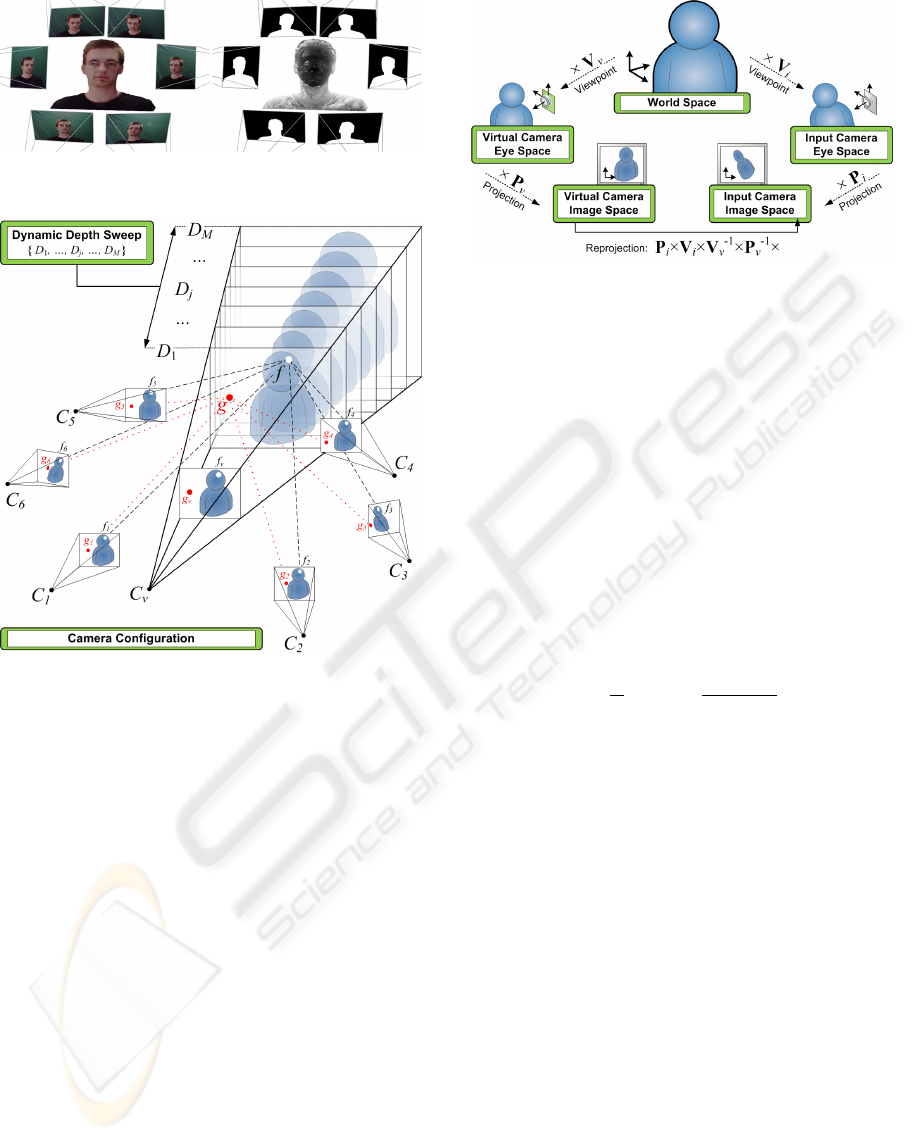
Figure 4: The view interpolation module generates a virtual
image and joint depth map.
Figure 5: Concept of the plane sweep algorithm.
final step, the silhouette is further enhanced by a sin-
gle erosion and dilation (Yang and Welch, 2002).
S
i
=
1 :
k
I
i
− I
B
i
k
> τ
f
or
k
I
i
− I
B
i
k
≥ τ
b
and cos(
d
I
i
I
B
i
) ≤ τ
a
0 :
k
I
i
− I
B
i
k
< τ
b
or
k
I
i
− I
B
i
k
≤ τ
f
and cos(
d
I
i
I
B
i
) > τ
a
(2)
Both methods are evaluated on a pixel basis and
require very little processing power, while still being
robust against moderate illumination changes.
2.2 View Interpolation
To interpolate the desired viewpoint (see Fig. 4) we
adopt and slightly modify a plane sweeping approach
based on (Yang et al., 2002). As depicted in Fig. 5, the
3D space is discretized into M planes {D
1
, . . . , D
M
}
parallel to the image plane of the virtual camera C
v
.
For each plane D
j
, every pixel f
v
of the virtual cam-
era image I
v
is back-projected on the plane D
j
by (3),
and reprojected to the input images I
i
according to (4).
Here T
j
is a translation and scaling matrix that defines
the depth and extent of the plane D
j
in world space.
Figure 6: Reprojection from virtual to input images.
The relationship between these coordinate spaces is
represented in Fig. 6.
f = V
−1
v
× P
−1
v
× T
j
× f
v
(3)
f
i
= P
i
× V
i
× f (4)
Points on the plane D
j
that project outside a fore-
ground silhouette in at least one of the input images,
are immediately rejected – e.g. point g in Fig. 5 – and
all further operations are automatically discarded by
the GPU hardware. This provides a means to lever
both speed and quality because segmentation noise
will, with a high probability, not be available in all
N cameras. Otherwise, the mean (i.e. interpolated)
color ψ and a jointly defined custom matching cost κ
are computed as in (5).
ψ =
N
∑
i=1
I
i
N
, κ =
N
∑
i=1
k
ψ − I
i
k
2
3N
(5)
As opposed to (Yang et al., 2002), we propose
the use of all input cameras to compute the matching
cost. The plane is swept for the entire search range
{D
1
, . . . , D
M
}, and the minimum cost – together with
the corresponding interpolated color – is per pixel se-
lected on a Winner-Takes-All basis, resulting in the
virtual image I
v
and a joint depth map Z
v
(see Fig. 4).
2.3 Joint View/Depth Refinement
The interpolated image calculated in the previous sec-
tion still contains erroneous patches (see Fig. 4, mag-
nified in Fig. 7) and speckle noise due to illumination
changes, partially occluded areas and natural homo-
geneous texturing of the human face. These errors
are even more apparent in the depth map Z
v
and we
therefore propose a photometric outlier detection al-
gorithm that detects and restores the patches in Z
v
.
To suppress the spatial high frequency speckle
noise, we consequently run a low-pass Gaussian fil-
ter over the depth map.
In a final step, the refined depth map is used to re-
color the interpolated image with the updated depth
SIGMAP 2008 - International Conference on Signal Processing and Multimedia Applications
238
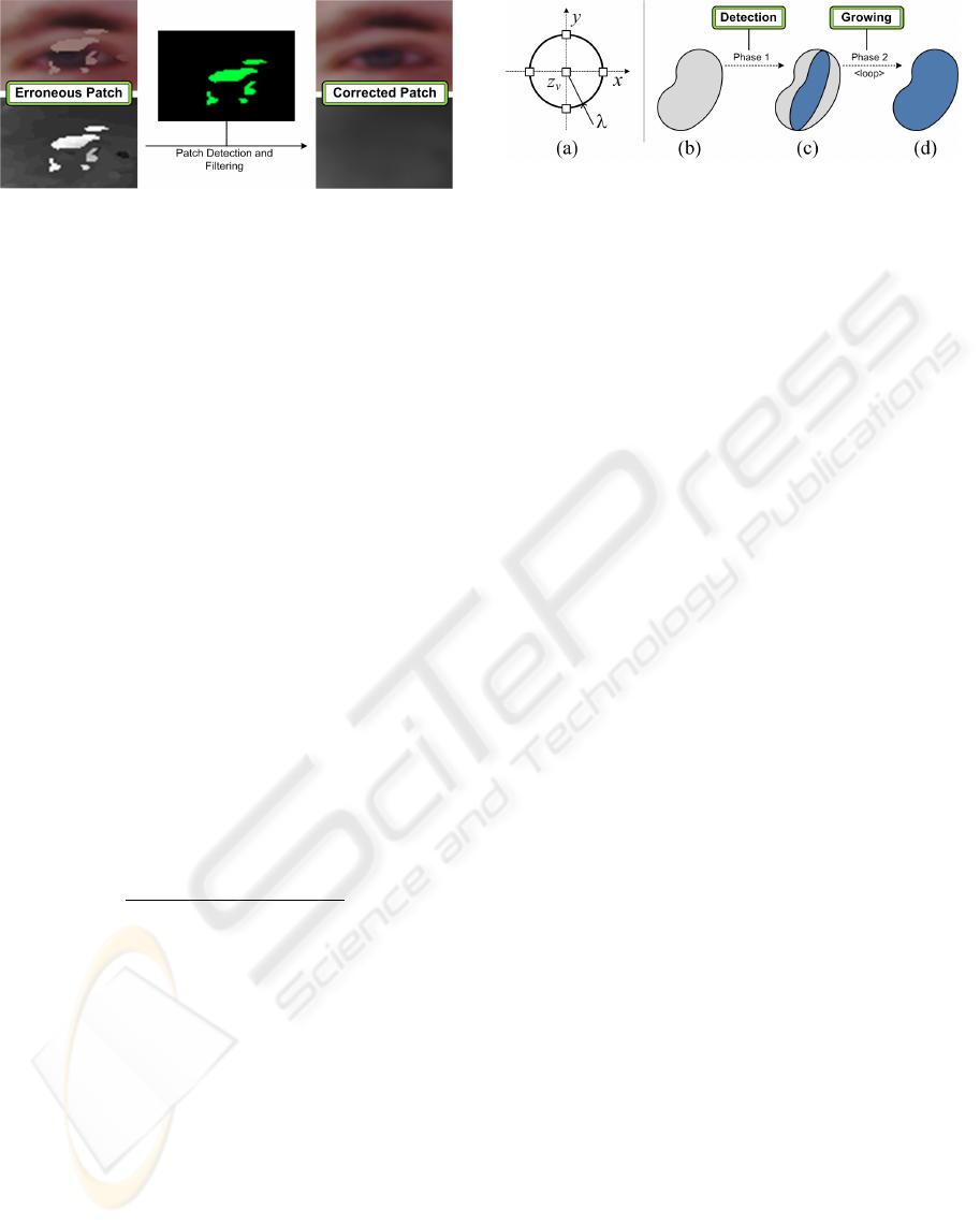
Figure 7: Joint view/depth refinement module concept.
values. As opposed to other geometrically correct ap-
proaches (Lei and Hendriks, 2002), we thereby sig-
nificantly enhance the subjective visual quality.
2.3.1 Erroneous Patch Filtering
To detect erroneous patches, we propose a filter kernel
as depicted in Fig. 8a. For every pixel z
v
of depth
map Z
v
, a two dimensional depth consistency check
is performed for its neighbourhood λ according to (6),
where ε is a very small constant to represent the depth
consistency. λ thereby defines the radius of the filter
kernel, and the maximum size of patches that can be
detected.
k
Z
v
(x − λ, y) − Z
v
(x + λ, y)
k
< ε or
k
Z
v
(x, y − λ) − Z
v
(x, y + λ)
k
< ε
(6)
If the area passes the consistency check in one of
the dimensions, the depth pixel z
v
– and therefore the
joint image pixel f
v
– is flagged as an outlier if z
v
does not exhibit the same consistency by exceeding a
given threshold τ
o
. Eq. (7) shows the outlier test when
a depth consistency is noticed in the X-dimension, an
analogous test is used in case of consistency in the
Y -dimension.
Z
v
(x, y) −
Z
v
(x − λ, y) + Z
v
(x + λ, y)
2
> τ
o
(7)
After performing the proposed filter kernel, the
center of patches – as conceptually represented in
Fig. 8b and Fig. 8c – are detected. Consistently, a
standard morphological grow algorithm is executed in
a loop, which causes the detected center to grow only
if the neighbouring pixels exhibit the same depth con-
sistency as the initial outliers. As depicted in Fig. 8d,
the complete patch is thereby detected. As a final
step for the patch filtering, the morphological grow
is reversed and the detected patch is filled with reli-
able depth values from its neighbourhood. Since all
of these operations are implemented on a pixel basis,
they are inherently appropriate for implementation on
a GPU, achieving a tremendous speedup compared to
a generic CPU algorithm.
Figure 8: (a) The proposed filter kernel, and (b–d) the out-
lier detection concept.
2.3.2 Speckle Noise Filtering
Due to the nature of the human face, a significant
amount of large homogeneous texture regions are
present. As indicated by (Scharstein and Szeliski,
2002) these areas cause the depth map to contain spa-
tial high frequency speckle noise. The noise is most
effectively filtered by a low-pass filter, but eliminates
the geometrical correctness of the depth map. There-
fore as opposed to methods such as (Lei and Hen-
driks, 2002), we rather enhance the subjective visual
quality instead of geometrical accuracy.
A standard 2D isotropic Gaussian filter is applied
on the depth map and thanks to its separable convo-
lution properties, it can even be highly optimized on
graphics hardware.
2.3.3 Recoloring
All of the previous steps involve changing the depth
map Z
v
, which is normally – due to the plane sweep
– jointly linked to the image color in I
v
. To restore
this link, the image I
v
is recomputed with an updated
T
j
matrix, according to the filtered depth information.
Since erroneous patches and speckle noise are now
filled or leveled with consistent – rather than geomet-
rically correct – depth values, the recolored image is
interpreted as plausible and thereby subjectively re-
garded as higher quality.
2.4 Movement Analysis
To avoid heavy constraints on the participant’s move-
ment, a large depth range has to be scanned. This ac-
tually infers a lot of redundant computations, since the
head of the user only spans a small range. We there-
fore propose to dynamically limit the effective depth
range to {D
min
, . . . , D
max
} similar to (Geys et al.,
2004), through a movement analysis on the normal-
ized depth map histogram. This implicitly causes a
quality increase of the plane sweep, as the probability
of a mismatch due to homogeneous texture regions is
significantly reduced. Moreover, all M depth planes
can be focused as {D
1
= D
min
, . . . , D
M
= D
max
},
A PROTOTYPE FOR PRACTICAL EYE-GAZE CORRECTED VIDEO CHAT ON GRAPHICS HARDWARE
239
which leverages the dynamic range and thereby sig-
nificantly increases the accuracy of the depth scan.
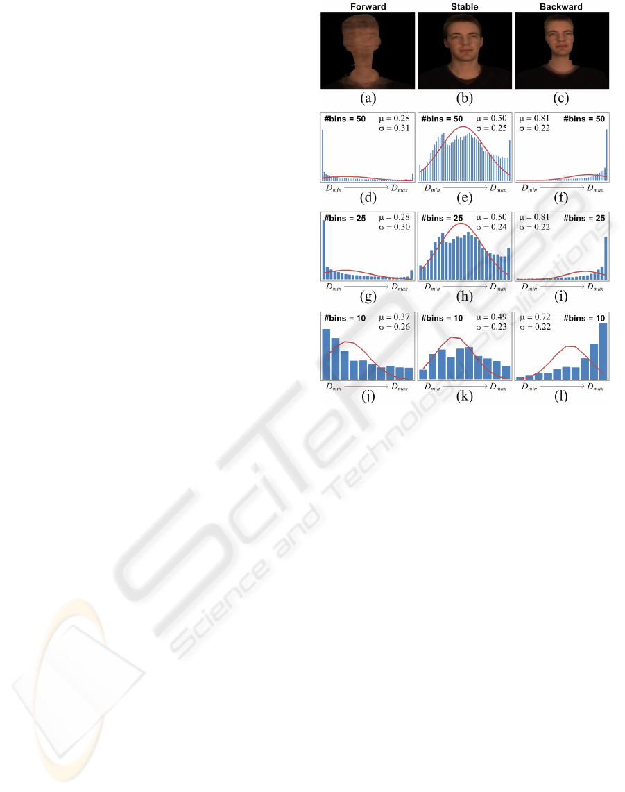
Three separate cases can be distinguished, as the user
moves in front of the screen:
• Forward: If the user moves forward, he will exit
the active scanning range. Therefore, the his-
togram will indicate an exceptionally large num-
ber of detected depth pixels towards D
min
.
• Stable: The histogram indicates a clear peak in
the middle, this resolves to the fact that the user’s
head remains in the same depth range.
• Backward: Analog to forward movement of the
user, the depth histogram will indicate a peak to-
wards D
max
.
As depicted in Fig. 9a to f, we fit a Gaussian distri-
bution function G (µ, σ) with center µ and standard de-
viation σ on the histogram. The effective depth range
is updated according to (8) and (9), where b
1
, b
2
are
constant forward and backward bias factors that can
be adopted to the inherent geometry of the scanned
object. D
0
min
represents the previous minimal depth,
and ∆ = D
0
max
− D
0
min
for denormalization.
D
1
= D
min
= D
0
min
+ (µ − b
1
· σ)∆ (8)
D
M
= D
max
= D
0
min
+ (µ + b
2
· σ)∆ (9)
As the user performs forward or backward move-
ment, the center µ of the Gaussian fit changes and dy-
namically adapts the effective scan range of the sys-
tem. The image will briefly distort in this unstable
case (see extreme cases in Fig. 9a and c), but will
quickly recover as the depth scan is adapted for ev-
ery image iteration. A real-time high framerate there-
fore increases the responsiveness of the system, and is
able to achieve fast restabilization. Normal moderate
speed movement will thereby not be visually noticed
by the participants.
2.5 Concurrent Eye Tracking
To restore the eye contact between the video chat par-
ticipants, the camera C
v
needs to be correctly po-
sitioned. Eye tracking can be performed more ro-
bust and efficiently on CPU, and is therefore executed
concurrently with the main processing of the system.
Afterall, the N input images are implicitly available
on system memory before they are sent to the video
memory of the GPU.
Face and eye candidates are detected in every in-
put image as described in (Hsu et al., 2002), but we
optimized the detection process by predicting the eye
positions based on previous frames and using a hierar-
chical approach to search for eye pixels. An epipolar
cross check is consequently used to estimate the most
Figure 9: Overview of the depth histogram-based move-
ment analysis in normalized coordinates.
reliable eye candidates in all images. The two best
eye candidates are ultimately used to triangulate their
3D positions.
The 3D eye position is then mirrored towards the
screen, resulting in the correct virtual viewpoint that
is needed to restore the eye contact between the sys-
tem users. The coordinates are adjusted in a man-
ner that places the two screens in a common space,
as if the two screens were pasted against each other.
Hence, this creates the immersive effect of a virtual
window into the world of the other participant.
2.6 Networking
Our prototype system sends the eye coordinates over
the network, and therefore the requested image I
v
can
be computed locally at the peer that captures the rel-
evant images. These cross computations bring the
required network communication to a minimum, by
avoiding the transfer of N input images. The total
peer-to-peer communication thereby exists out of the
synthesized images and the eye coordinates.
Real-time speed can therefore easily be achieved
over various types of networks without the need of
any compression. Due to the segmentation result S
v
,
the system can be efficiently equipped with Region-
SIGMAP 2008 - International Conference on Signal Processing and Multimedia Applications
240
of-Interest coding, to enable the use over low-data rate
networks as well.
3 OPTIMIZATIONS
Our framework harnesses the powerful computational
resources of the graphics hardware to ensure real-
time performance. The use of carefully selected and
adapted algorithms allows us to exploit the GPU for
general-purpose computations, a technique that is of-
ten referred to as General-Purpose GPU (GPGPU).
GPGPU is traditionally only capable of utilizing a
part of the GPU resources due to its computer graph-
ics nature (Owens et al., 2007). We optimized the
preprocessing to bypass this constraint, which lever-
ages the GPU utilization and execution speed without
any noticeable loss of quality.
Being an additional advantage, the histogram for
movement analysis is approximated by reducing its
number of bins, since only the correct Gaussian dis-
tribution fit is required.
As this approximation infers dynamic looping in-
side the GPU, we have built-in support for dynamic
GPU programming to be able to optimize and unroll
loops at run-time.
3.1 Improved Utilization
Standard lens distortion is generally corrected on a
pixel-basis level, but can be approximated by apply-
ing an equivalent geometrical undistortion to small
image tiles. Since a GPU pipeline exists out of a ge-
ometry and pixel processing stage, the lens correction
can hence be ported from the pixel to the geometry
stage. Initially, the computational complexity of the
undistortion is inverse proportional to the granularity
of the tessellation, resulting in a speedup without any
visual quality loss if the tile size is chosen correctly.
Next to this fact, the pixel processing stage is clear to
perform the consecutive segmentation processing in a
single pipeline pass, which significantly leverages the
utilization of the GPU.
3.2 Accelerated Histogramming
For the movement analysis, the essential part is de-
riving the parameters µ and σ to adjust the dynamic
range of the depth scan. As depicted in Fig. 9d to l,
we are able to approximate the histogram by reduc-
ing the number of bins, without a large impact on the
Gaussian parameters. Heavily reducing the number
of bins (see Fig. 9j to l) causes the center µ to be-
come less accurate, as it is shifted towards the center
of the effective scan range. An optimal trade-off point
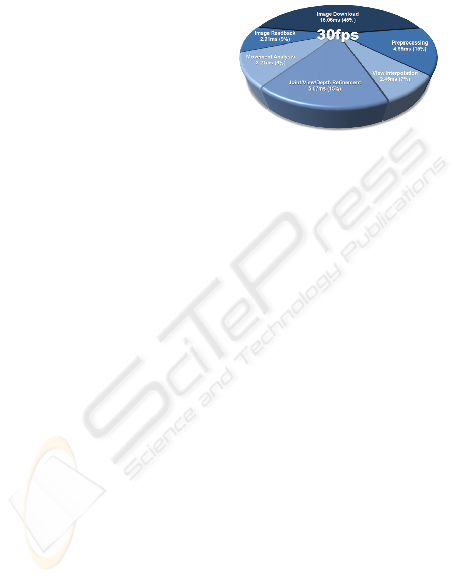
Figure 11: Workload profiling.
can therefore be defined, since the accuracy loss will
cause the responsiveness of the system to decrease.
3.3 Dynamic GPU Programming
Similar to the dynamic looping needed to variate the
number of bins in the histogramming, looping inside
the GPU is very often required. To enhance the ex-
ecution speed, our framework has built-in support to
generate and compile the GPU programming code at
run-time. Hereby, the loops can always be unrolled
and internally fully optimized.
4 RESULTS
Our optimal prototype setup is built with N = 6 auto-
synchronized Point Grey Research Grasshopper cam-
eras mounted on an aluminum frame, so they can
be closely aligned to the screen (See Fig. 1). The
presented camera setup avoids large occlusions, and
has the potential to generate high quality views since
no image extrapolation is necessary. We have used
the Multi-Camera Self-Calibration toolbox (Svoboda
et al., 2005) to calibrate the camera setup offline, but a
built-in camera setup into the screen would avoid this
procedure due to fixed calibration parameters. Our
software framework runs on an Intel Xeon 2.8GHz,
equipped with 2GB system memory and an NVIDIA
GeForce 8800GTX graphics card. Communication
with the GPU is done through OpenGL, and it is pro-
grammed with the high level language Cg.
Final quality results are shown in Fig. 10, under
moderate variable illumination conditions, but with
a fixed set of finetuned practical system parameters
grouped in Table 1. Some small artifacts along the
ears and chin, together with minor ghosting around
the neck, can still be noticed due to limitations of
the joint view and depth refinement. Nonetheless,
the images maintain their integrity and are regarded
A PROTOTYPE FOR PRACTICAL EYE-GAZE CORRECTED VIDEO CHAT ON GRAPHICS HARDWARE
241
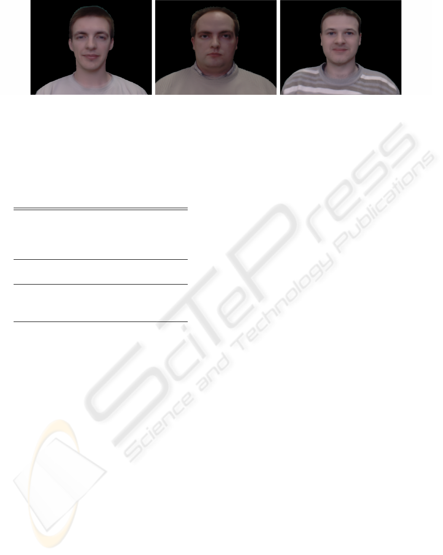
Figure 10: Eye-gaze corrected images with variable illumination and fixed optimal parameters.
as high subjective visual quality, while they convinc-
ingly seem to be making eye contact with the reader.
Table 1: Set of optimized system parameters.
Module Parameter Value
Preprocessing τ
g
0.355
τ
f
0.010
τ
b
0.002
τ
a
0.998
View Interpolation N 6
M 35
Joint View/Depth λ 20
Refinement ε 0.2
τ
o
0.3
Movement Analysis b
1
2.0
b
2
2.0
#bins 15
A detailed workload profiling for the main pro-
cessing modules can be seen in Fig. 11, with image
and camera resolutions of 800 × 600 pixels. A large
amount of time is needed to perform the six input im-
age download and synthesized image readback to and
from the GPU. Hence, the typical data locality im-
portance is illustrated, and the core reason to imple-
ment all main processing steps on graphics hardware
is motivated. The rather large weight for the prepro-
cessing is mainly due to the N = 6 times execution on
all input images. Furthermore, a significant amount
of processing is concentrated in the refinement and
movement analysis, as it levers the quality indepen-
dent of the amount of input images.
Summing up the different timings of the individ-
ual modules, we can reach a confident speed of 30fps,
but in our experimental setup is limited by 15Hz sup-
port in the cameras and Firewire controller hardware.
We foresee these specifications as for genuine prac-
tical usage, since the end-to-end system is optimized
for minimum practical constraints.
5 CONCLUSIONS
We have presented a system prototype for practical
eye-gaze correction between two video chat partici-
pants, with a minimal amount of constraints. A six-
fold camera setup that is closely aligned along the
screen, is proposed for possible integration into the
monitor frame. Besides the convenient camera place-
ment, the presented setup also avoids large occlu-
sions, and has the potential to generate higher qual-
ity views compared to camera setups that require con-
stant image extrapolation.
Our software framework harnesses the compu-
tational resources of the graphics hardware through
GPGPU, and is able to achieve real-time performance.
A framerate of 30fps can be achieved for 800 × 600
image resolutions, but our experimental setup is lim-
ited by 15 Hz cameras. Thanks to a movement analy-
sis, the system provides the user with a large freedom
of movement.
We have improved the end-to-end performance of
the system, by introducing optimizations that have no
noticeable loss of visual quality. A fixed set of fine-
tuned parameters is able to generate interpolated im-
ages with high subjective visual quality – rather than
being geometrically correct – under variable condi-
tions. Moreover, the system specifications thereby en-
able genuine practical usage of convincing eye-gaze
corrected video chat.
6 FUTURE WORK
Future work will focus on improving the movement
analysis. Furthermore, multiple objects can be intelli-
gently distinguished by combing silhouette informa-
tion, enabling eye-gaze corrected multi-party video
conferencing.
In the largest extent, background objects can be
recognized and interpolated with correct motion par-
allax, providing a true immersive experience for the
participants.
SIGMAP 2008 - International Conference on Signal Processing and Multimedia Applications
242

ACKNOWLEDGEMENTS
We would like to explicitly thank Tom Haber for the
development of the underlying software framework,
his contributions and suggestions.
Part of the research at EDM is funded by the Eu-
ropean Regional Development Fund (ERDF) and the
Flemish government.
We would also like to acknowledge the Interdis-
ciplinary Institute for Broadband Technology (IBBT)
for funding this research in the scope of the ISBO Vir-
tual Individual Networks (VIN) project.
Finally, co-author Sammy Rogmans is funded out-
side this project, by a specialization bursary from the
IWT, under grant number SB071150.
REFERENCES
Baker, H. H., Bhatti, N. T., Tanguay, D., Sobel, I., Gelb,
D., Goss, M. E., Culbertson, W. B., and Malzbender,
T. (2002). The coliseum immersive teleconferencing
system. In Proceedings of the International Workshop
on Immersive Telepresence, Juan-les-Pins, France.
Brown, D. C. (1966). Decentering distortion of lenses. Pho-
tometric Engineering, 32(3):444–462.
Chien, S.-Y., Yu, S.-H., Ding, L.-F., Huang, Y.-N., and
Chen, L.-G. (2003). Efficient stereo video coding
system for immersive teleconference with two-stage
hybrid disparity estimation algorithm. In ICIP 2003:
Proceedings of the 2003 International Conference on
Image Processing, pages 749–752.
Criminisi, A., Shotton, J., Blake, A., and Torr, P. H. S.
(2003). Gaze manipulation for one-to-one teleconfer-
encing. In ICCV ’03: Proceedings of the Ninth IEEE
International Conference on Computer Vision, page
191, Washington, DC, USA. IEEE Computer Society.
Gemmell, J., Toyama, K., Zitnick, C. L., Kang, T.,
and Seitz, S. (2000). Gaze awareness for video-
conferencing: A software approach. IEEE MultiMe-
dia, 7(4):26–35.
Geys, I., Koninckx, T. P., and Van Gool, L. (2004). Fast
interpolated cameras by combining a gpu based plane
sweep with a max-flow regularisation algorithm. In
3DPVT ’04: Proceedings of the 3D Data Process-
ing, Visualization, and Transmission, 2nd Interna-
tional Symposium, pages 534–541, Washington, DC,
USA. IEEE Computer Society.
Geys, I. and Van Gool, L. (2004). Extended view interpola-
tion by parallel use of the gpu and the cpu. In Video-
metrics VIII: Proceedings of the Society of Photo-
Optical Instrumentation Engineers (SPIE) Confer-
ence, volume 5665, pages 96–107.
Guo, X., Gao, W., and Zhao, D. (2005). Motion vector
prediction in multiview video coding. In ICIP 2005:
Proceedings of the 2005 International Conference on
Image Processing.
Hsu, R.-L., Abdel-Mottaleb, M., and Jain, A. K. (2002).
Face detection in color images. IEEE Transac-
tions on Pattern Analysis and Machine Intelligence,
24(5):696–706.
Lei, B. J. and Hendriks, E. A. (2002). Real-time multi-step
view reconstruction for a virtual teleconference sys-
tem. EURASIP Journal on Applied Signal Processing,
2002(1):1067–1087.
Magnor, M., Pollefeys, M., Cheung, G., Matusik, W., and
Theobalt, C. (2005). Video-based rendering. In SIG-
GRAPH ’05: ACM SIGGRAPH 2005 Courses, New
York, NY, USA.
Middlebury (2001). Middlebury stereo vision page.
www.middlebury.edu/stereo.
Nozick, V., Michelin, S., and Arqu
`
es, D. (2006). Real-time
plane-sweep with local strategy. In Journal of WSCG,
volume 14.
Owens, J. D., Luebke, D., Govindaraju, N., Harris, M.,
Krger, J., Lefohn, A. E., and Purcell, T. J. (2007).
A survey of general-purpose computation on graphics
hardware. Computer Graphics Forum, 26(1):80–113.
Rogmans, S., Lu, J., and Lafruit, G. (2008). A scalable
end-to-end optimized real-time image-based render-
ing framework on graphics hardware. In Proceedings
of 3DTV-CON, The True Vision, Capture, Transmis-
sion, and Display of 3D Video, pages 129–132, Istan-
bul, Turkey.
Scharstein, D. and Szeliski, R. (2002). A taxonomy and
evaluation of dense two-frame stereo correspondence
algorithms. International Journal of Computer Vision,
47(1–3):7–42.
Schreer, O., Brandenburg, N., Askar, S., and Trucco, M.
(2001). A virtual 3d video-conference system pro-
viding semi-immersive telepresence: A real-time so-
lution in hardware and software. In Proceedings of the
eBusiness-eWork Conference, pages 184–190, Venice,
Italy.
Svoboda, T., Martinec, D., and Pajdla, T. (2005). A con-
venient multi-camera self-calibration for virtual envi-
ronments. PRESENCE: Teleoperators and Virtual En-
vironments, 14(4):407–422.
Yang, R. and Pollefeys, M. (2003). Multi-resolution real-
time stereo on commodity graphics hardware. In 2003
IEEE Computer Society Conference on Computer Vi-
sion and Pattern Recognition, pages 211–220, Madi-
son, WI, USA. IEEE Computer Society.
Yang, R. and Welch, G. (2002). Fast image segmentation
and smoothing using commodity graphics hardware.
Journal of Graphics Tools, 7(4):91–100.
Yang, R., Welch, G., and Bishop, G. (2002). Real-time
consensus-based scene reconstruction using commod-
ity graphics hardware. In PG ’02: Proceedings of the
10th Pacific Conference on Computer Graphics and
Applications, page 225, Washington, DC, USA. IEEE
Computer Society.
A PROTOTYPE FOR PRACTICAL EYE-GAZE CORRECTED VIDEO CHAT ON GRAPHICS HARDWARE
243
