
A SMART SURVEILLANCE SYSTEM FOR HUMAN FALL-DOWN
DETECTION USING DUAL HETEROGENEOUS CAMERAS
Shaou-Gang Miaou, Cheng-Yu Chien, Fu-Chiau Shih
Multimedia Computing and Telecommunications Laboratory, Department of Electronic Engineering, Chung Yuan
Christian University, Chung-Li, 32023 Taiwan, R.O.C.
Chia-Yuan Huang
Industrial Technology Research Institute, Hsinchu, 310 Taiwan, R.O.C.
Keywords: Surveillance system, omni-directional camera, PTZ camera, fall detecting.
Abstract: We propose a new surveillance system that uses both omni-directional (OD) and Pan/Tilt/Zoom (PTZ)
cameras with heterogeneous characteristics and a relatively simple image processing algorithm to achieve
the goal of real time surveillance. The system is demonstrated for detecting the occurrence of human’s
fall-down event. An OD camera has a 360º viewing angle. It is used here to replace the multiple traditional
cameras having limited viewing angles in order to reduce the system cost. A PTZ camera is also used in the
system to track the target of interest and verify the occurrence of the event. Various unique features obtained
from OD images are used for fall down detection and a multi-classifier approach is used for better
recognition performance. Experimental results show that the system is quite robust to sudden changes of
walking paths and different directions of falling. During the tracking process, a moving target is captured
and its representative coordinates is obtained based on the processing of continuous OD images. The
coordinates of the target in the OD camera space will be converted to its corresponding three dimensional
(3D) coordinates in a real-world space. This derived information is served as guidance for the automatic
control of the PTZ camera to track the moving target as closely as it can. By combining the advantages of
two heterogeneous types of cameras, our experimental results show that the proposed system can track the
moving target well without the need of a complicated method, showing the feasibility and potential of the
system.
1 INTRODUCTION
With the rapid development of technology and
medical treatment, the average life span of human
increases. As a result, the percentage of the
population group with age 65 or more becomes
higher and higher in many parts of the world. The
number of the elderly with chronic disease,
melancholia, and psychosis is increasing as well.
The elderly suffer from the fall accidents more than
young people according to the statistics. A fall
accident not only causes physical injury but also
produces emotional disturbance for the elderly.
More and more elderly need long-term care
(Chen, 2002). However, there may not be enough
manpower to take care so many elderly. One way to
alleviate the seriousness of this manpower shortage
problem is to deploy a surveillance system for the
detection of fall down events and other dangerous
situations.
A traditional camera usually has a fixed viewing
angle that limits the possible coverage of
surveillance in an environment. Multiple cameras
are usually needed to cover the entire surrounding of
the environment. A Pan/Tilt/Zoom (PTZ) camera can
extend its viewing angles by constantly panning and
tilting the camera with a motor-controlled
mechanism. However, this is not very practical for
long-term surveillance because of the considerable
waste of power and the quick wearing of
motor-driven mechanical parts. Besides, the event of
interest may not be observed if the scanning cycle of
291
Miaou S., Chien C., Shih F. and Huang C. (2008).
A SMART SURVEILLANCE SYSTEM FOR HUMAN FALL-DOWN DETECTION USING DUAL HETEROGENEOUS CAMERAS.
In Proceedings of the International Conference on Signal Processing and Multimedia Applications, pages 291-299
DOI: 10.5220/0001933402910299
Copyright
c
SciTePress

the PTZ camera is much longer than the duration of
the event. Another way to extend the viewing angle
of a tradition camera is to put it on a moving carrier.
Although it can increase the cruising range of a
surveillance area, the area covered by the camera at
a time instant is still limited. And there may be some
dead spots left un-attended.
To solve the problems mentioned above,
Greiffenhagen et al. developed a new surveillance
system based on the use of an omni-directional (OD)
camera which basically consists of a traditional
camera and a convex mirror such that it has a 360º
viewing angle at any time instant (Greiffenhagen,
2001). After the OD camera was proposed, many
applications were developed based on the use of the
camera. For example, with the images taken by the
OD camera, Mituyosi et al. tried to capture and track
the features of a human face (eyes, mouths, etc)
(Mituyosi, 2003).
Although an OD camera can capture the image
from every angle at one shot, the resulting image is
distorted due to the use of the convex mirror.
Normally, the distortion level increases as it moves
from the center of the image to the border of the
image. In order to cover large surveillance areas
with reasonably good image quality, Morita used
several OD cameras and a computer network system
to connect them (Morita, 2003). Similarly, Lee also
used multiple OD cameras for outdoor surveillance
(Lee, 2002).
Again, the distortion from the convex mirror in a
PTZ camera could cause a serious problem for some
applications but it does have the advantage of the
broadest viewing angle. Thus, we use a PTZ camera
to replace the possible use of the second or more OD
cameras in our surveillance system. These two
heterogeneous types of cameras can be operated in a
complementary manner. We use an OD camera for
the preliminary tracking of a moving object in the
OD space and if the moving object presents the
features of interest, the system automatically
controls the PTZ camera to capture a sequence of the
undistorted and clear images that contain the moving
object for further visual inspection (by naked eyes).
Several advantages are associated with the system
that has such dual but heterogeneous cameras. First,
one OD camera can cover large enough surveillance
area with little dead spots. Second, the pan, tilt, and
zoom capability of the PTZ camera is fully exploited
to get clear visual information of the moving object
for better visual assessment. Third, the moving
object may be locked and stayed in locked by a PTZ
camera much more easily if the object’s location
information obtained from the OD images is
available. This dual camera system can be used in
many long-term and smart surveillance applications.
In this paper, we demonstrate its use in the detection
of human falling event in an indoor environment,
such as living room or sanatorium. Once a true
falling event is identified, emergency care may be
activated immediately to save lives. In this
application, we use an OD camera to detect the
falling event. If a suspicious event is detected by the
system, an alarm and/or message as well as PTZ
images will be sent to designated person who will
verify the event based on the PTZ images by naked
eyes. This will eliminate unnecessary false alarms
and enhance the reliability and credibility of the
system.
In the following sections, we will discuss the
issues of moving object extraction, fall-down event
recognition, and moving object tracking. The
experimental results and conclusion will be given in
the last two sections, respectively.
2 SYSTEM FRAMEWORK AND
FLOWCHART
We use the system framework shown in Figure 1.
First, we use an OD camera to capture the image of
the whole scene in a surveillance area. The resulting
OD images will be used to detect the existence of a
moving object. If a moving object is identified, its
representative coordinates on the OD image plane
will be converted to the real-world coordinates in a
three-dimensional (3D) space. The coordinate
information in 3D can be used to control a PTZ
camera such that the moving object can be tracked
and locked by the PTZ camera easily. The images
taken by the PTZ camera will be sent back to an
intended user of the surveillance system via some
network links for further visual inspection and
verification.
The system flowchart on signal processing tasks
is shown in Figure 2. Here, we use only simple and
basic image processing methods to capture a moving
object. Once the moving object is detected, we do
the coordinate conversion and fall detecting. If a
suspicious fall-down event is detected, PTZ images
will be sent to intended users to verify the event and
see if it is a true event or just a false alarm.
SIGMAP 2008 - International Conference on Signal Processing and Multimedia Applications
292
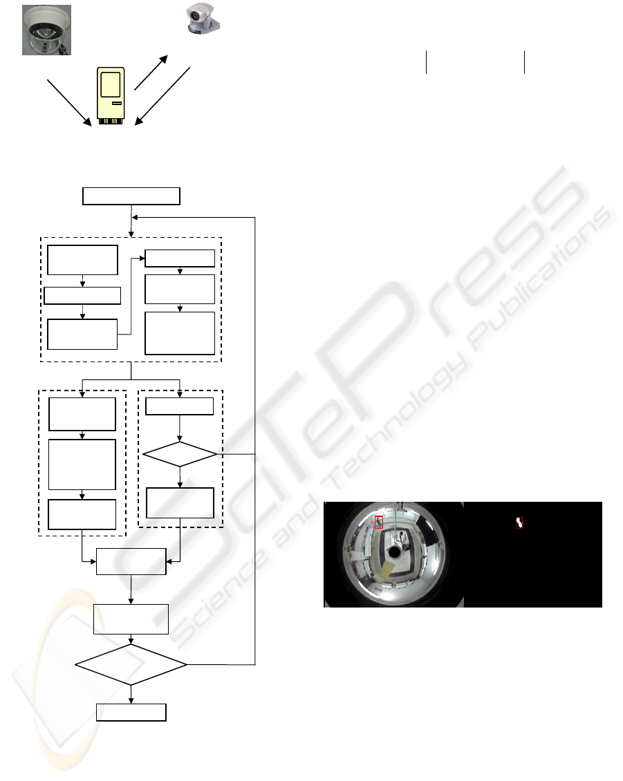
Figure 1: System framework.
Figure 2: System flowchart.
2.1 Object Capturing
The moving object detecting approach that we use
here is the background subtraction method which is
simple and well-known. As usual, background is
updated on a regular basis in order to overcome the
problem of light intensity change and/or chromatism.
We use Equation (1) to capture a foreground image.
),(),(),( yx
b
fyx
c
fyxD −=
(1)
where
),( yxf
c
denotes the pixel intensity at location
(x, y) of input image,
),( yxf
b
represents the pixel
intensity of background image at the same location,
and
),( yxD
denotes a difference image. Then we use
Equation (2) to eliminate the potential noise and
shadows and get a binarized image:
⎩
⎨
⎧
>
=
else0,
),( if,255
),(
ˆ
TyxD
yxD
(2)
where T is an empirical threshold. When
TyxD >),( ,
the system considers that a pixel at location (x, y) is
a potential pixel of the foreground image; otherwise,
it could be just part of noises or shadows that need to
be removed. Then we use some techniques in
morphology to capture a complete foreground image.
Finally, we use the well-known connected
component labeling method to identify the moving
object. Figure 3 shows an original image and a
foreground image after performing the image
processing tasks discussed above.
After the object of interest is captured, we use
two sub-systems for further processing. One is the
fall detecting sub-system, and the other one is the
object tracking sub-system.
(a)
(b)
Figure 3: The results of foreground image capturing. (a)
An original image; (b) A binarized image after noise
removal and connected component labeling.
2.2 Fall Detecting Sub-System
2.2.1 Method
When a falling event occurs, the human body
usually has significant movement. Thus, we define
body line of human body next and use the features
associated with the body line for fall-down
recognition later. Figure 4 shows the two scanning
Input Image
Object extraction
Coordinate
conversion
Background
Removing
Color-to-Gray
Binarization
Erosion &
Dilation
Median
Filtering
Connected
Component
Labeling
Calculate d,
α, β
Calcula
t
e the
Position in
Real-World
Space
PTZ
Tracking
Falling
Preliminary
Warning
Get Features
N
Y
Switch
Button
Fall Detecting
Verification
Rescue
Actual
Warning
N
Y
Fall detecting
OD camera
Image
input
PTZ control
Image
sent
PTZ camera
A SMART SURVEILLANCE SYSTEM FOR HUMAN FALL-DOWN DETECTION USING DUAL
HETEROGENEOUS CAMERAS
293
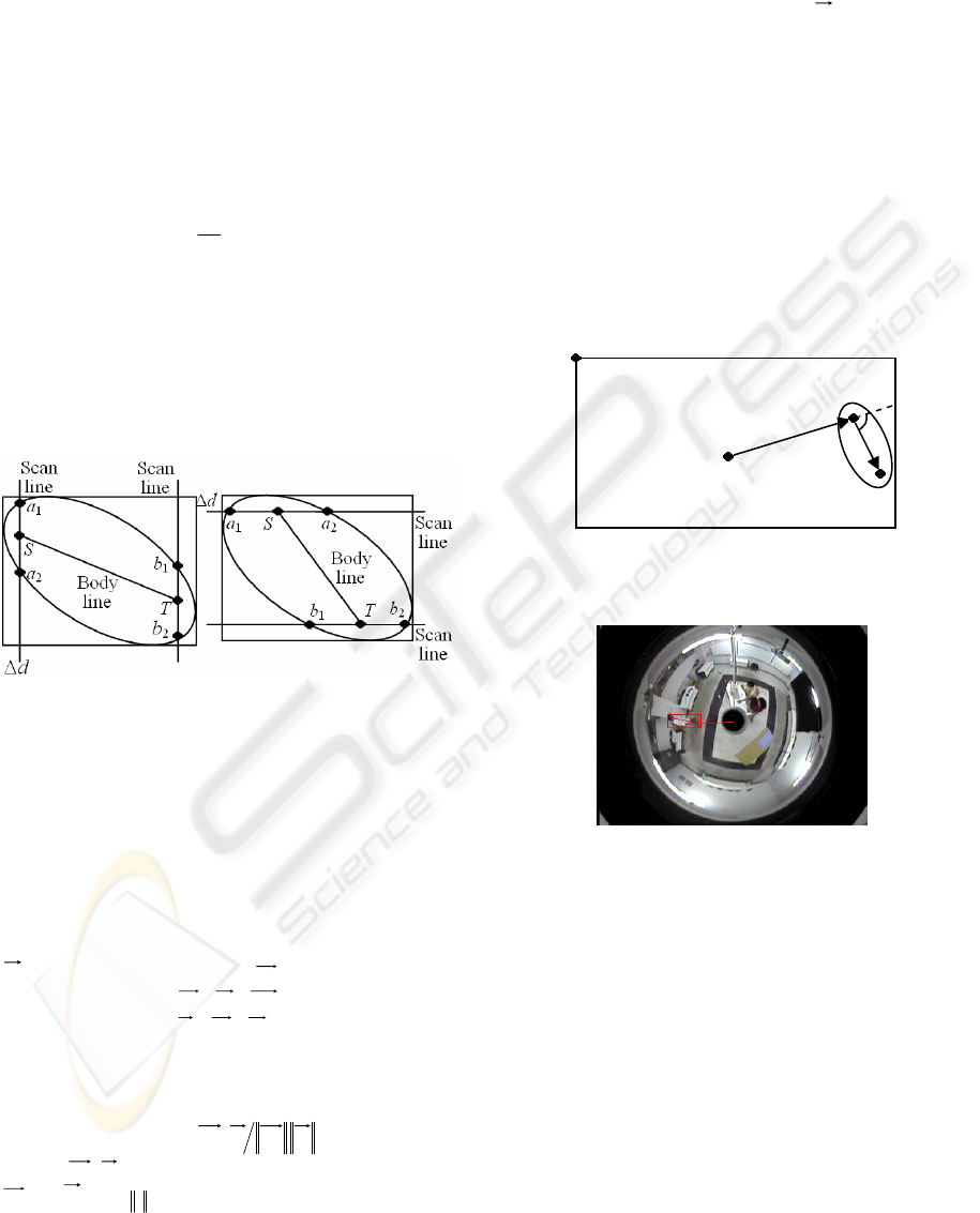
methods to find the body line. One is horizontal
scanning, and the other is vertical scanning. In
Figure 4, the ellipse is used to represent the
foreground and the rectangle is used to represent the
smallest bounding box that encloses the foreground.
All we need is the human body, so each scan line is
dΔ pixels away from its closest sideline to avoid
the inclusion of head and feet parts. The
a
1
, a
2
, b
1
,
and
b
2
are the intersecting points at which the scan
lines and the boundary of the foreground object
intersect. In addition, Points
S and T are the
midpoints for
a
1
and a
2
, and for b
1
and b
2
,
respectively. Finally,
ST
segment is the potential
body line. Figure 4 shows the results of horizontal
scans and vertical scans, resulting in two body lines,
and we choose the longer one as our final body line.
We need both horizontal and vertical scans instead
of one of them in order to avoid the situation of
wrong body line selection when the major axis of the
ellipse is parallel to the x-axis or y-axis.
(a) (b)
Figure 4: Finding a body line segment. (a) Vertical
scanning; (b) Horizontal scanning.
After the body line segment is found, we rename
the end points of the segment and call them
I and J
according to the following rule: The end point closer
to the center
M (where the OD camera is located) is
called
I and the other end point is called J, as shown
in Figure 5. Next, we define a body line vector
IJ
and a reference line vector
MI
as follows:
OMOIMI −=
(3)
OIOJIJ −=
(4)
where
O is the origin located at the top left corner
of the image. The angle
θ
between these two
vectors is defined as
)(
1
cos IJMIIJMI ⋅
−
=
θ
(5)
where
IJMI ⋅
is the inner product of the vectors
MI
and
IJ
, and
•
denotes the norm operation. Figure
6 shows a typical body line vector and a reference
line vector imposed on a real-world OD image.
Next, we define the features used for the
recognition of fall down event:
(1) The angle
θ
defined in Equation (5).
(2) The length
L of body line vector
IJ
.
(3) The
x coordinate of the midpoint of body line.
(4) The
y coordinate of the midpoint of body line.
(5) The ratio
ρ
between the length and the width of
the rectangle shown in Figure 4.
One set of these five features can be obtained for
one image frame. Multiple sets of features can be
obtained for the multiple frames contained in an
observing window. Let
K be the number of frames in
the observing window. Then this sliding window is
moved such that any two adjacent windows contain
K - 1 identical image frames and one different frame.
In this study, we set
K to be 15.
Figure 5: A pictorial representation of body line and
reference line vectors.
Figure 6: A typical OD image imposed by body line and
reference line vectors and a bounding box (rectangle).
Figure 7 shows the recognition flowchart of the
proposed system. Here, a two-stage multiple
classifiers is designed to classify the feature vectors
form by the feature values discussed above. The first
(stage) classifier attempts to classify three classes:
normal (do not fall), falling down in non-radial
direction, and suspicious fall-down in radial
direction. If the last class is determined by the first
classifier, then the system uses a second (stage)
classifier to reduce the false alarm rate. The second
classifier is based on the Back-Propagation Neural
Network (BPNN).
O
θ
M
I
J
SIGMAP 2008 - International Conference on Signal Processing and Multimedia Applications
294
Figure 7: System flowchart of our multiple classifiers.
2.2.2 First Classifier – Simple Decision
Criteria
We found that the angle feature defined in Equation
(5) does not change much when a target is walking
in a normal way or standing according to our
experiment. Furthermore, a large angle variation
occurs when the fall-down in non-radial direction
happens. The simple decision criteria below are used
to determine whether the non-radial directional
falling occurs.
(1) The average of angle feature values is higher
than a preset threshold (indicating the target may be
falling).
(2) The displacement of body line midpoint is
lower than another preset threshold (indicating the
target ceases moving).
If both conditions above are met, the system
determines that a non-radial directional fall-down
event occurs. However, we can not get a high
enough angle variation for radial-direction fall-down,
as shown in Figure 8. Thus, we need new
recognition features and decision criteria for this
situation. We found that when the target falls in
radial direction, the length of body line vector
changes significantly in some observing windows.
Thus, we define two other decision criteria with
different features below to deal with this situation:
(1) The variance estimate of body line lengths is
higher than a preset threshold.
(2) The displacement of body line midpoint is
lower than another preset threshold.
We also found that the body movements for
sitting and squatting also satisfy the two conditions
above. Thus, if the two conditions above are met, we
can only claim that we have a suspicious case of
radial-direction fall-down. Further differentiation
between radial-direction fall-down and sitting or
squatting is necessary. This is the objective of the
second classifier discussed next.
Figure 8: Body line vector and reference vector almost
align with each other in radial-direction fall-down.
2.2.3 Second Classifier and Multiple
Classifiers
We observed that at least 15 frames are required to
complete the process of sitting, squatting, and
radial-direction falling. Thus, the system monitors
15 continuous frames and record five parameter
values. These five parameters correspond to the five
features defined in Section 2.2.1:
(1) The angle
θ
defined in Equation (5);
(2)
L
Δ
: The difference of the length L obtained
from two adjacent frames;
(3)
x
Δ
: The displacement in X direction for the
x coordinates obtained from two adjacent frames;
(4)
y
Δ
: The displacement in Y direction for the
y coordinates obtained from two adjacent frames;
(5)
ρ
Δ
: The variation between the two ratios
ρ
obtained from the bounding boxes in two adjacent
frames. For each frame in the observing window,
these five parameter values are obtained. For 15
consecutive frames, we have a total of 75 parameter
values which become the input to the BPNN for
training and testing.
2.3 Object Tracking Sub-System
Once an object is obtained, a critical point is defined
as the object point that is closest to the center of OD
image. The coordinates of this critical point in the
OD space will be converted to the real-world 3D
coordinates that could be useful for the guidance
control of PTZ cameras. Because the image taken by
an OD camera is projected from real-word space (as
N
First Classifie
r
Input features
Fall detecting
criterion met
Y
Second
Classifier
Warning
Normal
Normal
Warning
Simple criteria
O
θ=0
M
I
J
N
on-radial directional falling
Suspicious radial directional falling
A SMART SURVEILLANCE SYSTEM FOR HUMAN FALL-DOWN DETECTION USING DUAL
HETEROGENEOUS CAMERAS
295
shown in Figure 9), it is possible to find the
corresponding point in real-world space for a point
in the OD space. In other words, we need to find the
point mapping from OD space to real-world space.
(a) (b)
Figure 9: Two different coordinate spaces. (a) A real-world
3D space; (b) Image taken by an OD camera in the OD
space.
We know that a point Q’ in the real-world space
as shown in Figure 9(a) can be projected to the CCD
sensor in an OD camera through the reflex of the
convex mirror, resulting in the corresponding point
Q in the OD space as shown in Fig. 9(b). This idea is
further illustrated in Figure 10. After we capture the
critical point in the OD image [marked by ◎ in
Figure 11(a)], we can calculate some useful
parameter values as follows:
22
YX
QQd +=
(6)
⎟
⎟
⎠
⎞
⎜
⎜
⎝
⎛
=
−
X
Y
Q
Q
1
tan
α
(7)
where
d represents the distance between the critical
point to the center of OD image and
α is the angle of
that point with respect to the
x-axis, as shown in
Figure 11.
Figure 10: Imaging principle of an OD camera (Yu, 1999).
In addition, the coordinates of 'Q can be derived
as
-
tan
sin
,
tan
cos
,
'
⎥
⎥
⎦
⎤
⎢
⎢
⎣
⎡
= m
mm
Q
β
α
β
α
(8)
where
m denotes a known constant, representing
the vertical distance (or height) from the floor to the
OD camera, and
β
denotes the vertical angle of the
critical point with respect to the
x-y plane in Figure
10.
(a) (b)
Figure 11: Position of a critical point in OD space. (a) an
OD image; (b) parameter calculated from the OD image
information.
We can find the corresponding position of the
critical point in real-world space by Equation (8) but
we still need one more value for the parameters
other than the
d and α calculated previously.
Specifically, we need to find the value for the
parameter tan
β. However, it can not be obtained
directly from OD images. In fact, we need to
estimate it and one way to do so is as follows. First,
design an
n-point line array pattern as shown in
Figure 12. Then, we attempt to find the position
mapping between the points in the OD image and
their corresponding points in real-world space. As
shown in Figure 12, we have
l
h
i
i
=
β
tan
(9)
r
d
k
i
i
= (10)
where
i
β
denotes the angle β for Point i (or P
i
),
i
h
represents the vertical distance between the plane
x-y
in real-world space and Point
i (or P
i
), l is the
horizontal distance between the line in the array
pattern and the center of the OD camera in
real-world space,
i
d is the distance from Point i to
the OD image center in OD space,
r
is the radius of
the largest circle containing meaningful image data
in OD images, and
i
k is a known ratio for Point i.
Numerical values of these parameters are shown in
Table 1 (only one third is shown). Given these data
set, we use a MATLAB curve fitting tool to calculate
the best relationship curve between tan
β
and k. The
result is in Equation (11):
22
6032.0
0442.0
226.0
1158.0
068.2929.9tan
⎟
⎟
⎠
⎞
⎜
⎜
⎝
⎛
−
−
⎟
⎟
⎠
⎞
⎜
⎜
⎝
⎛
+
−
×+×=
kk
ee
β
(11)
Therefore, given the radius
r and the distance d,
we get
k from Equation (10) and then obtain the
value for tan
β
from Equation (11). Finally, we get
the converted coordinates in real-world space by
using Equation (8).
After we get an estimate for the coordinates of
α
β
x
y
z
Q
"Q
'Q
sensorCCD
Y
Q
X
Q
α
Q
SIGMAP 2008 - International Conference on Signal Processing and Multimedia Applications
296
the critical point in real-world space, we can send
proper commands to the PTZ camera via RS232 port
by properly setting panning, tilting, and zooming
such that the moving target can be centered in the
resulting PTZ images with appropriate size. For a
new critical point detected, the PTZ camera may
need a different set of commands to control it
properly. Continue in this way, the moving object
can be tracked effectively.
(a) (b)
Figure 12: Experiment trying to find the relationship
between two coordinate spaces (Hsu, 2004). (a) Data
points in real-world space; (b) data points after projection.
Table 1: Relationship between tan
β
and k.
i l (mm) h (mm) tanβ
i
k
i
d (pixel) r (pixel)
1 33.0
0.24 0.90
104
2 36.0
0.27 0.88
102
3 41.0
0.30 0.86
100
4 47.0
0.35 0.84
97
5 57.5
0.43 0.80
93
6 68.0
0.50 0.76
88
7 84.2
0.62 0.72
83
8 100.5
0.74 0.66
76
9 122.0
0.90 0.59
69
10 143.0
1.06 0.52
60
11 170.0
1.26 0.47
54
12 197.0
1.46 0.41
47
13 229.0
1.70 0.36
42
14 261.0
1.93 0.32
37
15
135
298.5
2.21 0.28
33
116
3 RESULTS AND DISCUSSION
3.1 Fall Detecting
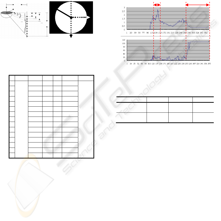
Figure 13 shows a possible value variation for
Feature (5) and Feature (1) given in Section 2.2.1. It
is found that the values for ratio features may change
significantly in both walking and falling, while the
values of angel feature change significantly only in a
falling situation. Thus, the angle feature may be
more robust than the ratio feature with respect to
different walking paths.
The evaluation criteria we use for the fall
detection sub-system are accuracy, specificity, and
Kappa values (Siegel, 1988) (Lee, 2000). Table 2
shows the performance comparison between the
results of using a single (first stage) classifier and a
multiple classifiers. The multiple-classifier approach
always outperforms the single classifier method.
This demonstrates the effectiveness of the second
stage classifier in the sub-system.
Figure 13: A comparison between ratio and angle features.
Table 2: Performance comparison between single classifier
approach and multiple-classifier approach.
Accuracy Specificity Kappa
Simple
criterion
0.82 0.72 0.64
Multiple
classifier
0.87 0.88 0.73
3.2 Real-Time Tracking
We give a simple experiment to evaluate the
precision of the tracking sub-system. A target is
asked to walk along a specified path. Then the
system predicts the walking path based on the
information from OD images and the coordinate
conversion formula given in Equation (8). The result
shows that the predicted walking path is quite close
to the actual walking path, but some errors exist. The
errors may come from image processing (wrong feet
or critical point positions are obtained) and the
curving fitting formula given in Equation (11) for
tan
β
.
We check several fixed and known points to
verify the precision of the coordinate conversion
formula. Eight points shown in Figure 14 are
selected in our experiment. The results are shown in
Table 3.
As Table 3 shows, the error could be as high as
β
1
β
2
β
3
β
n
P
1
P
2
P
3
P
n
h
n
h
1
h
2
h
3
x
z
y
l
n
P
3
P
1
P
−n
2
P
1
P
r
Fall
happened
Walking
Ratio
Angle
Fra
m
Fra
m
A SMART SURVEILLANCE SYSTEM FOR HUMAN FALL-DOWN DETECTION USING DUAL
HETEROGENEOUS CAMERAS
297
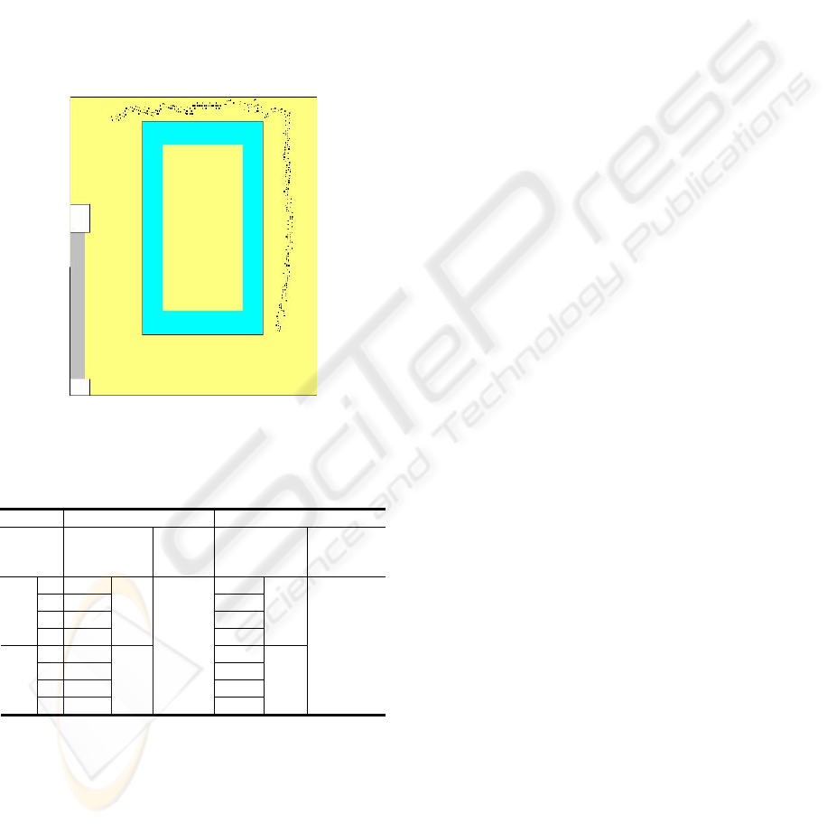
10 pixels or more. However, the size of the image
considered here is 752*771 and the errors in
X-direction and Y-direction are about 0.8% and
0.84%, respectively. Thus, the error is relatively
small and thus the formula in Equation (11) is
acceptable. We can also see that the errors in the
inside block are smaller than those in outside block.
The reason is that the input image is distorted more
seriously in the outside block than in the inside
block. Therefore, we found that bad image
processing result (such as wrong feet detecting) is
the main source contributing the error and the curve
fitting equation has little contribution on inaccuracy.
Figure 14: Top-view diagram of experimental environment
(Size: 752*771).
Table 3: Errors for coordinate conversion.
X direction Y direction
Position
Error
(pixels)
Average
error
(pixels)
Error
(pixels)
Average
error
(pixels)
a 0.33
7.07
b 5.30
2.00
c 7.23
0.27
Inside
d 2.99
3.96
10.16
4.88
e 8.38
1.45
f 12.00
16.78
g 0.79
9.67
Outside
h 11.20
8.09
6.03
0.19
7.02
5.95
In Li’s work, a PTZ camera must be installed
directly under an OD camera and no coordinate
conversion is used (Li, 2006). Several drawbacks are
associated with the approach proposed by Li. First,
the installation constraint may prevent its system
from being practical because the installation of the
system may not be possible in some environments.
Second, the PTZ camera can cover a limited
surveillance area (with only 180viewing angle). In
other words, half of the room can not be seen. Third,
the tracking accuracy in Li’s approach may be
inferior since no coordinate conversion is used for
error compensation. In our proposed system, we do
not have the installation constraint mentioned above.
Theoretically, it can be installed anywhere in the
environment. Of course, some locations may be
more suitable than others in practical consideration.
We conducted two more experiments to further
illustrate the problems associated with the approach
proposed by Li and demonstrate the advantages with
the proposed approach in this paper. One is for the
environment where the PTZ camera is installed
directly under the OD camera (Point A in Figure 15),
and the other is for the environment where the PTZ
camera is installed at anywhere except just under the
OD camera (Point B in Figure 15). Again, we assign
a walking path for a target to follow and compare the
prediction accuracy of the path obtained by the two
approaches.
In the first experiment, since the PTZ camera is
put right under the OD camera, the accuracy results
for the approaches are quite similar and are not
shown here. In addition, a common drawback of this
installation is the limited viewing angle. For
example, suppose someone moves from Point B to
Point C along the BC segment and the PTZ camera
points to the exact south from the center in Figure 15.
In this case, half of the BC segment cannot be seen
and the tacking can not continue. In the second
experiment, we install the PTZ camera at Point B.
Note that the approach by Li uses the detected
moving target directly from OD images without any
correction. So if the target walks along the straight
line BC, the line will be distorted and becomes a
curve as shown in Figure 15. This curve rather than
straight line information is provided to the PTZ
camera for tracking. Thus, with this erroneous
information, smooth and continuous tracking
becomes harder in this case. This drawback will not
occur with the proposed approach. Since we have
corrected the distortion in some extent, the detected
path is roughly a line (as Figure 14 shows). With this
more accurate information, the smooth and
continuous tracking by the PTZ camera is easier. In
summary, the proposed approach has advantages
over the one proposed by Li, although additional
computation is required.
e
a
c
g
f
h
d
b
SIGMAP 2008 - International Conference on Signal Processing and Multimedia Applications
298

Figure 15: OD image showing an assigned path.
4 CONCLUSIONS
In this paper, a smart surveillance system for human
fall-down event detection based on dual
heterogeneous cameras is proposed. We attempt to
combine the advantages of both OD camera and PTZ
camera. Specifically, we can use the wide viewing
angle capability provide by the OD camera for
preliminary tracking and fall detecting, followed by
the use of a PTZ camera for fall detection
verification, face detection or other possible
applications. The precision for the coordinate
conversion between two coordinate spaces is good.
The feet detection error in image processing is the
main contribution of the inaccuracy. In our system, a
PTZ camera can be installed at the best location for
surveillance in real-world situation, which can offer
installation flexibility and convenience.
ACKNOWLEDGEMENTS
This work is supported in part by the National
Science Council of R. O. C. under Contract
NSC-95-2221-E-033-069-MY3.
REFERENCES
Chen, M. S. (2002). The Empirical Research on the
Elderly Living in Nursing Homes --- Illustrated by the
Elders the Three Public Nursing Home of Chiayi City.
Master Thesis, NanHua University, Taiwan, R.O.C.
Greiffenhagen, M., Comaniciu, D., Neimann, H., &
Ramesh, V. (2001). Design, Analysis, and Engineering
of Video Monitoring Systems: An Approach and A
Case Study, Proc. of IEEE, vol. 89, no. 10, pp.
1498-1517.
Hsu, M. Y. (2004). An Application of the Panoramic
Camera to the Positioning and the Path Planning of An
Automatic Navigated Vehicle, The 21th National Conf.
on Mechanical Eng., The Chinese Society of
Mechanical Eng. pp.1725-1730, 2004.
Lee, J. W., You, S., & Neumann, U. (2002). Tracking
with Omni-directional Vision for Outdoor AR
Systems, Proc. of the Int. Symp. on Mixed and
Augmented Reality, pp. 47-56.
Lee, T. W. (2000). Statistics, Taipei: Best-Wise Publishing
Co., Ltd.
Li, C. K. (2006). Using Omni-Directional and PTZ
Cameras to Implement Real-Time Tracking of Moving
Objects on a DSP Board, Master Thesis, Dept. of
Electronic Eng., Chung-Yuan Christian University,
Taiwan, R.O.C.
Mituyosi, T., Yagi, Y., & Yachida, M. (2003). Real-time
Human Feature Acquisition and Human Tracking by
Omni-directional Image Sensor, Proc. of IEEE Conf.
on Multisensor Fusion and Integration for Intelligent
System, pp. 258-263.
Morita, S., Yamazawa, K. & Yokoya, N. (2003).
Networked Video Surveillance Using Multiple
Omnidirectional Cameras, Proc. of IEEE Int.
Symposium on Comput. Intelligence in Robotics and
Automation, pp. 1245-1250, Kobe, Japan.
Siegel, S., & Castellan, N. (1988). Nonparametric
Statistics for the Behavioral Sciences, 2nd Ed. New
York: McGraw-Hill.
Yu, F. P. (1999). Using Panoramic Video Camera Direct
Pan-Tilt-Zoom Cameras. Master Thesis, National
Taiwan University, Taiwan, R.O.C.
B
C
A
A SMART SURVEILLANCE SYSTEM FOR HUMAN FALL-DOWN DETECTION USING DUAL
HETEROGENEOUS CAMERAS
299
