
VIRTUAL FREQUENCY REUSE TO INCREASE CAPACITY OF
OFDM SYSTEMS
Seung-Moo Cho and Tae-Jin Lee
School of Information and Communication Engineering, Sungkyunkwan University, Suwon, 440-746, South Korea
Keywords:
Frequency reuse, fractional frequency reuse (FFR), orthogonal frequency division multiplexing (OFDM), re-
source management.
Abstract:
This paper presents a novel frequency reuse scheme that reduces the effects of co-channel interference and in-
creases the capacity of orthogonal frequency division multiplexing (OFDM) systems. To increase the capacity
of a system, the frequency reuse factor should be close to 1. In general, reduction of co-channel interference
(CCI) is achieved at the cost of cell capacity. Our virtual frequency reuse (VFR) targets to mitigate such
tradeoff. In VFR, the type of a cell is determined by the order of sub-channel assignment. And users in a
cell are assigned sub-carriers among sub-channels by a specific regulation. Probabilistic interference analysis
and simulation results show that the proposed virtual frequency reuse improves the performance of an OFDM
system for both uniform and non-uniform distributions of traffic load.
1 INTRODUCTION
To support the emergence of new wireless appli-
cations and the proliferation of multimedia ser-
vices, broadband wireless access (BWA) has been re-
searched (A. Jamalipour and Yamazato, 2005). Due
to limited spectral resources, next-generation wireless
networks require some techniques to utilize frequency
spectrum efficiently. The orthogonal frequency divi-
sion multiplexing (OFDM) is considered as one of the
best solutions to satisfy this requirement (M. Sternad
and Brunstrom, 2007), (M. Bohge and Meyer, 2007).
In OFDM, the parallel transmission of data symbols
deceases the effect of intersymbol interference (ISI),
which is appropriate for BWA.
To increase the spectral efficiency in OFDM, spec-
tral resource management is necessary. Many chan-
nel assignment techniques are proposed to manage
spectral resources efficiently in OFDM systems. Ba-
sically, channel assignment techniques are classified
into fixed channel assignment (FCA) and dynamic
channel assignment (DCA). FCA assigns a set of
channels to each cell permanently. So, FCA is simple
and shows reasonable performance. However, if a cell
has high traffic load and the other cells have lowtraffic
load, the spectral resources may not be managed effi-
ciently in FCA. To improvethe shortcomings of FCA,
DCA is proposed (S. Anand and Sivarajan, 2003). In
DCA, channels may be assigned to cells during a spe-
cific time duration and the assignment changes dy-
namically. It reflects the traffic condition of each cell
and manages the spectral resources efficiently. Since
DCA causes unexpected interference to neighboring
cells, interference avoidance algorithms are required.
Combining FCA and DCA, borrowing channel as-
signment (BCA) is proposed (Jiang and Rappaport,
1996). A cell in high traffic condition can borrow
channels from neighboring cells to accept incoming
calls. BCA improves the performance of FCA and
reduces the overhead caused by exchange of channel
assignment in DCA.
In wireless cellular systems, the frequency reuse is
employed to reduce the effects of co-channel interfer-
ence (CCI) and to increase the capacity of a system.
The reuse factor should be close to 1 to increase the
system capacity. But, the reduction of CCI is achieved
at the cost of cell capacity. To mitigate such tradeoff,
some techniques such as reuse partitioning and frac-
tional frequency reuse (FFR) have been studied (Chu
and Rappaport, 1997), (Forum, 2006). Reuse parti-
tioning uses multiple reuse factors. Overlaid cells are
implemented to reduce the CCI in reuse partitioning.
FFR has constraints on a usable set of channels in
cells to balance the tradeoff between the cell capac-
ity and the interference.
In this paper, we propose a new virtual frequency
135
Cho S. and Lee T. (2008).
VIRTUAL FREQUENCY REUSE TO INCREASE CAPACITY OF OFDM SYSTEMS.
In Proceedings of the International Conference on Wireless Information Networks and Systems, pages 135-139
DOI: 10.5220/0002021601350139
Copyright
c
SciTePress
reuse (VFR) to increase the capacity of OFDM sys-
tems. FFR has heavy constraints on sub-channels sets
used in each cell. It tends to limit the spectrum ef-
ficiency of a system. VFR, however, allows that all
sub-channel sets can be flexibly assigned to each of
cells, and it may have constraints on the order of sub-
channel sets used in each cell. Each sub-channel set in
our VFR is assumed to have the same size, and static
reuse set management is applied. As a sub-carrier al-
location algorithm, both static and dynamic schemes
can be employed in VFR. The remainder of this paper
is organized as follows. Section II describes FFR and
VFR. In Section III, the system model is introduced
and the simulation results are presented and analyzed.
Finally, we conclude in Section IV.
2 PROPOSED VIRTUAL
FREQUENCY REUSE
2.1 Fractional Frequency Reuse
Mobile WiMAX proposes FFR to accomodate more
subscribers (Forum, 2006). FFR is a technique that
has constraints on usable sub-channel sets for each
cell. The conventional frequency reuse techniques
have the similar constraints. In addition, FFR has the
common sub-channel set that is commonly assigned
to all cells.
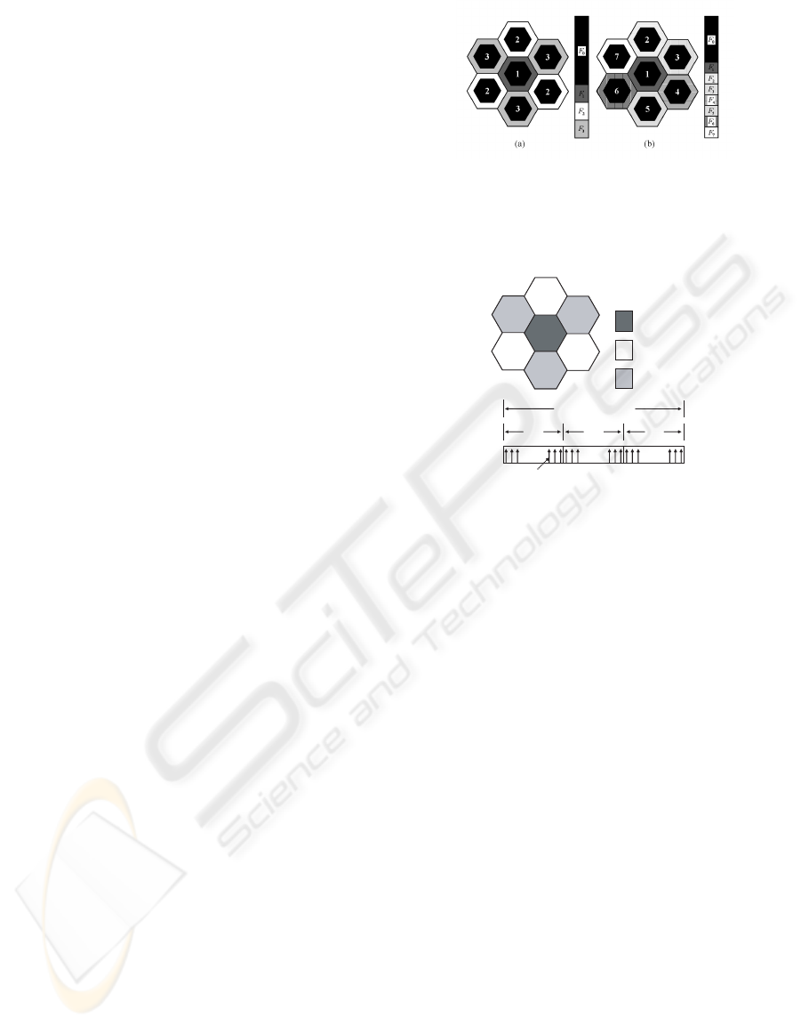
In FFR, a frequency partitioning scheme deter-
mines the usable sub-channel sets for each cells. Fig.
1 shows an example of frequency partitioning in FFR.
Each cell has the common sub-channel set and dedi-
cated sub-channel set that is assigned to specific cells.
The ratio of the number of sub-carriers in common
sub-channel set to the number of total sub-carriers
is determined by the sub-channel allocation schemes.
And sub-channel sets are managed statically or dy-
namically by the reuse set management algorithm.
Although the common sub-channel set increases the
capacity of a system, there is a limit on usable sub-
channel sets since each cell is allowed to use only the
dedicated sub-channel, i.e., part of whole bandwidth.
For example, in Fig. 1(a), cell 1 is allowed to use only
the dedicated sub-channel F
1
among F
1
∼F
3
.
2.2 Proposed Virtual Frequency Reuse
We propose VFR as a novel frequency reuse tech-
nique to increase the capacity of OFDM systems. In
VFR, each cell has the reuse factor of 1 and the vir-
tual reuse factor of M, where M is the size of a clus-
ter. Hence, all sub-channels(sub-carriers) in a system
Figure 1: An example of frequency partitioning in FFR, (a)
frequency partitioning with the cluster size of 3, (b) fre-
quency partitioning with the cluster size of 7. F
0
is the
common sub-channel and F
1
∼F
7
are the dedicated sub-
channels.
))) යය
))) යය
))) යය
7RWDO6XE&KDQQHO
)
)
)
7\SH
2UGHURIVXEFKDQQHO
DOORFDWLRQ
VXEFDUULHU
7
&HOO
7
&HOO
7
&HOO
7
&HOO
7
&HOO
7
&HOO
7
&HOO
7
L
7
L
7
L
))) යය
))) යය
))) යය
))) යය
))) යය
))) යය
7RWDO6XE&KDQQHO
)
)
)
7RWDO6XE&KDQQHO
)
)
)
7\SH
2UGHURIVXEFKDQQHO
DOORFDWLRQ
VXEFDUULHU
7
&HOO
7
&HOO
7
&HOO
7
&HOO
7
&HOO
7
&HOO
7
&HOO
7
L
7
L
7
L
Figure 2: Proposed Virtual Frequency Reuse (VFR), cluster
size M = 3.
can be allocated to users in every cell. But the cells
are categorized into M types by a virtual reuse factor.
Each cell follows a specific regulation to allocate sub-
channels by its cell type. All sub-carriers are indexed
in a sequential manner, and then they are partitioned
into M sub-channel sets by performing modular M op-
erations on their index numbers. So each sub-channel
set is represented as follows:
F
m
= {f
k
|k modM = m, 1 ≤ k ≤ N},
0 ≤ m ≤ M −1 (1)
where f
k
is the kth sub-carrier and N is the number of
total sub-carriers. Let T
i
denote the type of cell i, and
0 ≤ T
i
≤ M −1. In each cell type, sub-channels are
allocated sequentially to users by a specific order as
follows:
T
i
= t : F
(t)modM
→ F
(t+1)modM
→ ... → F
(t+M−1)modM
.
Fig. 2 shows the frequency partitioning of VFR.
The system has the virtual frequency reuse factor of
M = 3. Each sub-channel set is represented as F
0
, F
1
and F
2
. For each cell type, sub-channels are allocated
sequentially as follows:
T
i
= 0 : F
0
→ F
1
→ F
2
,
T
i
= 1 : F
1
→ F
2
→ F
0
,
T
i
= 2 : F
2
→ F
0
→ F
1
.
WINSYS 2008 - International Conference on Wireless Information Networks and Systems
136

For Type 0 cell, when a new call is arrived, prefer-
entially sub-carriers in F
0
are assigned to users in a
random manner. If all sub-carriers in F
0
are assigned
to users, sub-carriers in F
1
are allocated to users for
incoming calls. It starts to allocate sub-carriers in F
2
after all sub-carriers in F
0
and F
1
have been allocated
to users. For Type 1 and Type 2 cells, the same strat-
egy is applied except the ordering of allocation of sub-
channel sets.
3 PERFORMANCE EVALUATION
3.1 Interference Estimation
To comparethe performance of VFR, we consider two
FFR schemes. FFR1 is a conventional FFR scheme
which does not have the ordering of sub-channels al-
location. FFR2 is the same as FFR1 except that it
has the ordering of sub-channels allocation. In FFR2,
the dedicated sub-channels are first allocated to users.
The ratio of the number of sub-carries in the common
sub-channel set to the number of total sub-carriers is
0.7 in FFR1 and FFR2. And the cluster size is 3 in
FFR1, FFR2 and VFR. The traffic loads of cell i and
cell j are defined as λ
i
, λ
j
.
λ
i
=
N
use
i
N
total
i
, λ
j
=
N
use
j
N
total
j
(2)
where N
use
i
and N
use
j
are the number of sub-carriers
used in cell i and j, and N
total
i
and N
total
j
are the num-
ber of total sub-carriers for cell i and j, respectively.
We first estimate the interference of VFR proba-
bilistically from neighboring cells to roughly capture
the amount of interference. We consider the cluster
size M = 3. The probability of the event that a sub-
carrier in use in cell i is also used in cell j is repre-
sented as a function of λ
i
and λ
j
. Let P[F
i
0
], P[F
i
1
] and
P[F
i
2
] be the probability that arbitrary sub-carrier used
in cell i is in sub-channel set F
0
, F
1
and F
2
, respec-
tively. And the probability that a sub-carrier is used
in cell i is also used in neighboring cell j is defined
as P[I
T
i
,T
j
i, j
]. P[I
T
i
,T
j
i, j
] is represented in different forms
according to the ranges of λ
i
and λ
j
. For example,
the probability of the event that sub-carrier used in
cell i which is Type 0 is also used in cell j, which is
Type 1, is calculated as follows. For
2
3
≤ λ
i
< 1 and
1
3
≤ λ
j
<
2
3
,
P[F
i
0
] =
1
3λ
i
, (3)
P[F
i
1
] =
1
3λ
i
, (4)
P[F
i
2
] =
3λ
i
−2
3λ
i
. (5)
And the conditional probabilities,
P[I
0,1
i, j
|F
i
0
] = 0, (6)
P[I
0,1
i, j
|F
i
1
] = 1, (7)
P[I
0,1
i, j
|F
i
2
] = 3λ
j
−1. (8)
Therefore,
P[I
0,1
i, j
] =
2
∑
k=0
P[I
0,1
i, j
|F
i
k
]P[F
i
k
]
=
(3λ
j
−1)(3λ
i
−2) + 1
3λ
i
. (9)
In a similar manner, the interferences of VFR,
FFR1 and FFR2 from each type of cells can be found
as a function of λ
i
and λ
j
. Fig. 3 shows the probabil-
ity, P[I
0,T
j
i, j
], under varying traffic load where λ
i
= λ
j
.
VFR decreases the probability of interference occur-
rences to the other type cells. In the same type cells,
the probability shows increase. However, since the
same type cells j are located at 2-tier of cell i, the total
effects of interference is not significant indeed. This
is validated in our simulation in the following section.
In FFR2 and VFR, some critical points can be ob-
served. Since two schemes adopt the ordering of sub-
channel allocation, at the boundary of sub-channel al-
location, P[I
T
i
,T
j
i, j
|T
i
= T
j
] may converge to 1.
3.2 Simulation
We assume that λ
j
is Gaussian random variable to
model the traffic load of cell j, which is a neigh-
boring cell of cell i, and compare the performance
of each frequency reuse technique under uniform and
non-uniform distribution among cells. The mean of
λ
j
is the same as that of λ
i
. We consider mobile
WiMAX systems. The link level parameters are set
0 0.1 0.2 0.3 0.4 0.5 0.6 0.7 0.8
0
0.1
0.2
0.3
0.4
0.5
0.6
0.7
0.8
0.9
1
Offered Traffic Load
Probability
FFR1(cell j: Type 0)
FFR2(cell j: Type 0)
VFR(cell j: Type 0)
FFR1(cell j: Type 1, Type 2)
FFR2(cell j: Type 1, Type 2)
VFR(cell j: Type 1, Type 2)
Figure 3: The probability P[I
T
i
,T
j
i, j
] that a sub-carrier used in
cell i is also used in a neighboring cell j (T
i
= 0, T
j
=0, 1 or
2, λ
i
= λ
j
, p = 0.7).
VIRTUAL FREQUENCY REUSE TO INCREASE CAPACITY OF OFDM SYSTEMS
137
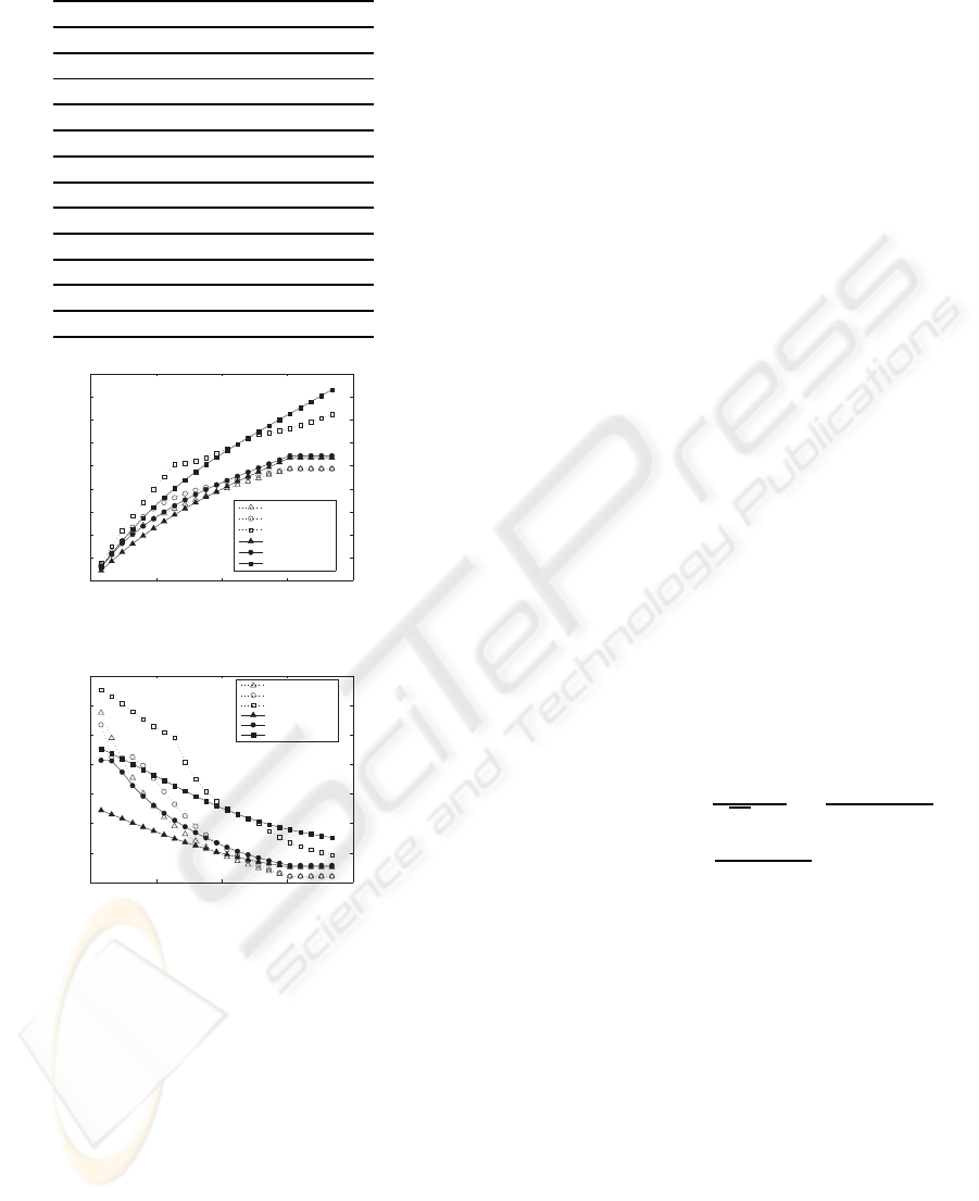
Table 1: MCS table for modulation and coding scheme.
Modulation Code Rate SIR
QPSK 1/12 -4.34
QPSK 1/8 -2.80
QPSK 1/6 -1.65
QPSK 1/4 0.13
QPSK 1/3 1.51
QPSK 1/2 4.12
QPSK 2/3 6.35
16QAM 1/2 9.50
16QAM 2/3 12.21
64QAM 1/2 13.32
64QAM 2/3 16.79
64QAM 5/6 20.68
0 50 100 150 200
0
2000
4000
6000
8000
10000
12000
14000
16000
18000
Number of MSs
Total Throughput (kbps )
FFR1(variance:0)
FFR2(variance:0)
VFR(variance:0)
FFR1(variance:0.1)
FFR2(variance:0.1)
VFR(variance:0.1)
Figure 4: Total throughput of cell i.
0 50 100 150 200
60
80
100
120
140
160
180
200
Number of MSs
Average Throughput (kbps )
FFR1(variance:0)
FFR2(variance:0)
VFR(variance:0)
FFR1(variance:0.1)
FFR2(variance:0.1)
VFR(variance:0.1)
Figure 5: Average throughput of MS in cell i for varying
number of MSs.
as follows: carrier frequency = 2.3 GHz, sampling
frequency = 10 MHz, FFT size = 1024, the number
of used sub-carriers = 864, the number of data sub-
carriers = 768, the number of pilot sub-carriers = 96
and the symbol rate = 9.76 ksymbols/sec. Modulation
schemes and error correction codes are determined by
the reported SIR. Table 1 shows the modulation and
coding scheme (MCS) table for FFR and VFR. The
number of cells is 19 considering interference from 2-
tier cells. The distance between base stations is 1km
and the transmission power at base station is 20 W.
Considering the carrier frequency and the cell radius,
COST-WI urban micro model is applied as a channel
model (D. S. Baum and Salo, 2005).
PL(d) = 31.81+ 40.5log(d). (10)
Fig. 4 shows the total throughput of cell i. Under
uniform traffic load distribution (variance=0), VFR
has better performance in medium and high traffic
load. Under non-uniform traffic load distribution
(variance=0.1), VFR improves the throughput perfor-
mance significantly in high traffic load and has the
maximum spectrum efficiency of 1.7 bps/Hz. There
are two critical points in the plot of VFR with vari-
ance 0. At each critical point, VFR improves the
cell capacity significantly. Especially, VFR improves
the throughput performance about 30% compared to
that of FFR2 under the condition that the offered load
(mean) and variance are 0.33 and 0, respectively. In
FFR1 and FFR2, the total throughput of a system is
saturated at 154 MSs since the dedicated sub-channel
sets for specific cells limit the overall spectral re-
sources. Fig. 5 shows the average throughput of
users. It presents the similar trend as in Fig. 4. When
the number of MSs is 154, the average throughput
improves 36% (variance=0) and 34% (variance=0.1)
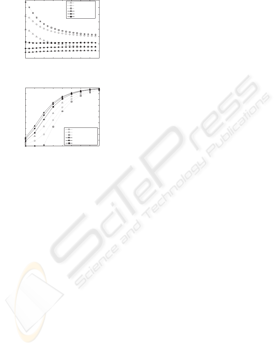
overFFR2. In Fig. 6, the effect of trafficload distribu-
tion is also shown. In low traffic load (mean=0.267),
as the traffic load distribution becomes more uniform,
our VFR shows more improved average throughput.
Fig. 7 shows the outage probability of each of fre-
quency reuse techniques. The outage probability can
be obtained as follows:
P
outage
(SIR
o
) = P[SIR < SIR
o
] (11)
=
Z
SIR
o
0
1
√
2πσ
SIR
exp[
−(x−m
SIR
)
2
2σ
2
SIR
]dx
= 1−Q(
SIR
o
−m
SIR
σ
SIR
),
where SIR
o
is an SIR threshold. It demonstrates
that an OFDM system using VFR as a frequency reuse
scheme can support quality of service (QoS) require-
ments of mobile stations. The simulation results in-
dicate that VFR mitigates the tradeoff effect between
the system capacity and QoS.
4 CONCLUSIONS
We have proposed a novel frequency reuse technique,
VFR. We have analyzed the system performance by
probabilistic estimation of interference and compared
with other FFR techniques. Both analysis and sim-
ulation results demonstrate that VFR improves the
throughput and outage performance under both uni-
form and non-uniform traffic conditions among cells.
WINSYS 2008 - International Conference on Wireless Information Networks and Systems
138
0 0.05 0.1 0.15 0.2 0.25 0.3 0.35 0.4
70
80
90
100
110
120
130
140
150
Variance
Average Throughput (kbps )
FFR1(mean: 0.267)
FFR2(mean: 0.267)
VFR(mean: 0.267)
FFR1(mean:0.533)
FFR2(mean:0.533)
VFR(mean:0.533)
Figure 6: Average throughput with the effect of non-
uniform traffic load distribution.
0 5 10 15 20 25 30 35 40
0
0.1
0.2
0.3
0.4
0.5
0.6
0.7
0.8
0.9
1
SIR threshold (dB)
Outage probability
FFR1(traffic load:0.267)
FFR2(traffic load:0.267)
VFR(traffic load:0.267)
FFR1(traffic load:0.533)
FFR2(traffic load:0.533)
VFR(traffic load:0.533)
Figure 7: Outage Probability (variance=0, P = 0.7).
In this paper, static sub-carrier allocation scheme is
considered. VFR, however, allows both static and dy-
namic sub-carrier allocation, which is under investi-
gation for future work.
ACKNOWLEDGEMENTS
This research was supported by a grant under the
Brain Korea 21 Initiative of the Korean Ministry of
Education and Human Resources and by the Korea
Science and Engineering Foundation(KOSEF) grant
funded by the Korea government(MOST) (No. R01-
2006-000-10402-0) and by MKE, Korea under ITRC
IITA-2008-(C1090-0801-0046).
REFERENCES
A. Jamalipour, T. W. and Yamazato, T. (2005). A tutorial
on multiple access technologies for beyond 3g mo-
bile network. In IEEE Communications Magazine,
43(2):110-117. IEEE Communications Society.
Chu, T.-P. and Rappaport, S. S. (1997). Overlapping cover-
age with reuse partitioning in cellular communication
systems. In IEEE Transactions on Vehicular Technol-
ogy, 46(1):41-54. IEEE Vehicular Technology Soci-
ety.
D. S. Baum, J. H. and Salo, J. (2005). An interim chan-
nel model for beyond-3g systems: extending the 3gpp
spatial channel model (scm). In Vehicular Technology
Conference, 2005. VTC 2005-Spring. 2005 IEEE 61st,
5:3132-3136. IEEE Vehicular Technology Society.
Forum, W. (2006). Mobile WiMAX-part I: a technical
overview and performance evaluation. WiMAX Fo-
rum.
Jiang, H. and Rappaport, S. S. (1996). Prioritized channel
borrowing without locking: a channel sharing strategy
for cellular communications. In IEEE/ACM Transac-
tions on Networking, 4(2):163-172. IEEE Communi-
cations Society, IEEE Computer Society, and Associ-
ation for Computing Machinery.
M. Bohge, J. Gross, A. W. and Meyer, M. (2007). Dynamic
resource allocation in ofdm systems: an overview of
cross-layer optimization principles and techniques. In
IEEE Network, 21(1):53-59. IEEE Communications
Society.
M. Sternad, T. Svensson, T. O. A. A. A. S. and Brunstrom,
A. (2007). Towards systems beyond 3g based on adap-
tive ofdma transmission. In Proceedings of the IEEE,
95(12):2432-2455. IEEE.
S. Anand, A. S. and Sivarajan, K. N. (2003). Performance
analysis of channelized cellular systems with dynamic
channel allocation. In IEEE Transactions on Vehicular
Technology, 52(4):847-859. IEEE Vehicular Technol-
ogy Society.
VIRTUAL FREQUENCY REUSE TO INCREASE CAPACITY OF OFDM SYSTEMS
139
