A VEHICULAR HEALTHCARE SYSTEM USING ANYCAST AND
PERVASIVE COMPUTING
One Pervasive Computing Application on Mobile Software and Services
Max Meng-Yu Lee and Jiun-You Wang
ITRI- Industrial Technology Research Institute, No. 31, Gongye 2
nd
Rd., Annan District, Tainan City 709, Taiwan (R.O.C.)
Keywords: Anycast, Pervasive Computing, Vehicular Healthcare System, Multicast.
Abstract: One vehicular healthcare system is proposed to provide secure and stable transmission in wireless
environments. Using anycast and pervasive computing technology, the robustness and real-time
transmission model is provided for the ambulance to communicate with the target hospital via wireless
GPRS transmission in very limited and tolerant data loss. The message reliable transmission method
between the ambulance and the hospital with 3 Transmission Devices connecting to 3 GPRS networks is
proposed. Each time two out of three TDs are selected to transmit the packet and its duplicate. Using
anycast, it doesn’t cause the overload condition as with multicast, one MRN selection method is proposed
for the router to achieve the load-balancing condition in MRG.
1 INTRODUCTION
The healthcare system is gradually important as the
people getting old and resident far away from the
hospital and the nursing people. We proposed this
paper with the system architecture and the message
reliable transmission method are parts of the
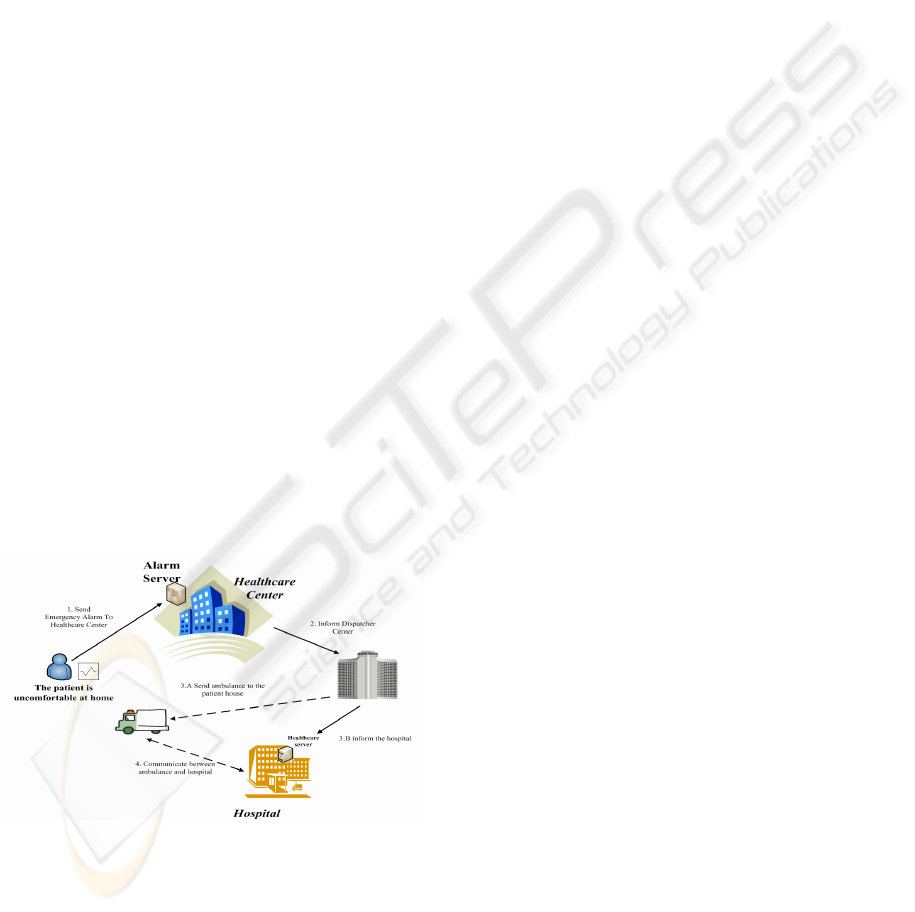
healthcare system project as depicted in Figure 1.
Figure 1: Project view - the healthcare system.
Normally the aged or health-cared person is vital
sign monitored by the sensor devices with
periodically sending the data to the healthcare center.
At the moment of uncomfortable from the monitored
person and showing the urgent data to the alarm
server, the healthcare center will inform the
dispatcher center to send the ambulance to the
patient’s house and also ask the target hospital to
prepare. After the ambulance arrived and the patient
is carried into the ambulance, our proposed
vehicular healthcare system is started to set up the
secure stable communication to the hospital.
The most important feature of healthcare system
is the secure and stable data transmission capability.
When sufficient information is provided to the
doctors and the nursing people, they thus can do the
correct judge. But the data loss probability exists,
and the hardware cost can not be too huge, therefore
we need to find the trade-off point.
The paper describes the vehicular healthcare
system providing stable transmission in wireless
environments. Using anycast and pervasive
computing, one robustness and real-time
transmission model is provided for the ambulance
to communicate with the hospital via wireless
GPRS transmission.
Anycast is defined in RFC3068 (HINDER,
DERRING, 1995), and has great difference with
multicast and broadcast. When the data is
transmitted, via broadcast, each network node can
receive the data; via multicast, only these network
nodes in that multicast group can have the data; via
anycast and underlying routing protocols, only one
of network nodes in the anycast group has the data.
219
Meng-Yu Lee M. and Wang J. (2008).
A VEHICULAR HEALTHCARE SYSTEM USING ANYCAST AND PERVASIVE COMPUTING - One Pervasive Computing Application on Mobile
Software and Services.
In Proceedings of the International Conference on Wireless Information Networks and Systems, pages 219-224
DOI: 10.5220/0002022302190224
Copyright
c
SciTePress
Anycast is very suitable to provide stable
services (Dow, Hsuan, Hwang, 2006) (Metz, 2002)
(Matsunaga, Ata, Kitamura, Murata, 2005); each
network node in the same group, whether far or near
to the user, can provide the same service, and the
user doesn’t need to care where the service nodes
are, but can access the service with the group
address; especially while one of group network
nodes is failed (Jia, Xu, Zhao, 2000), the remaining
nodes can still provide the same service via
underlying routing protocols.
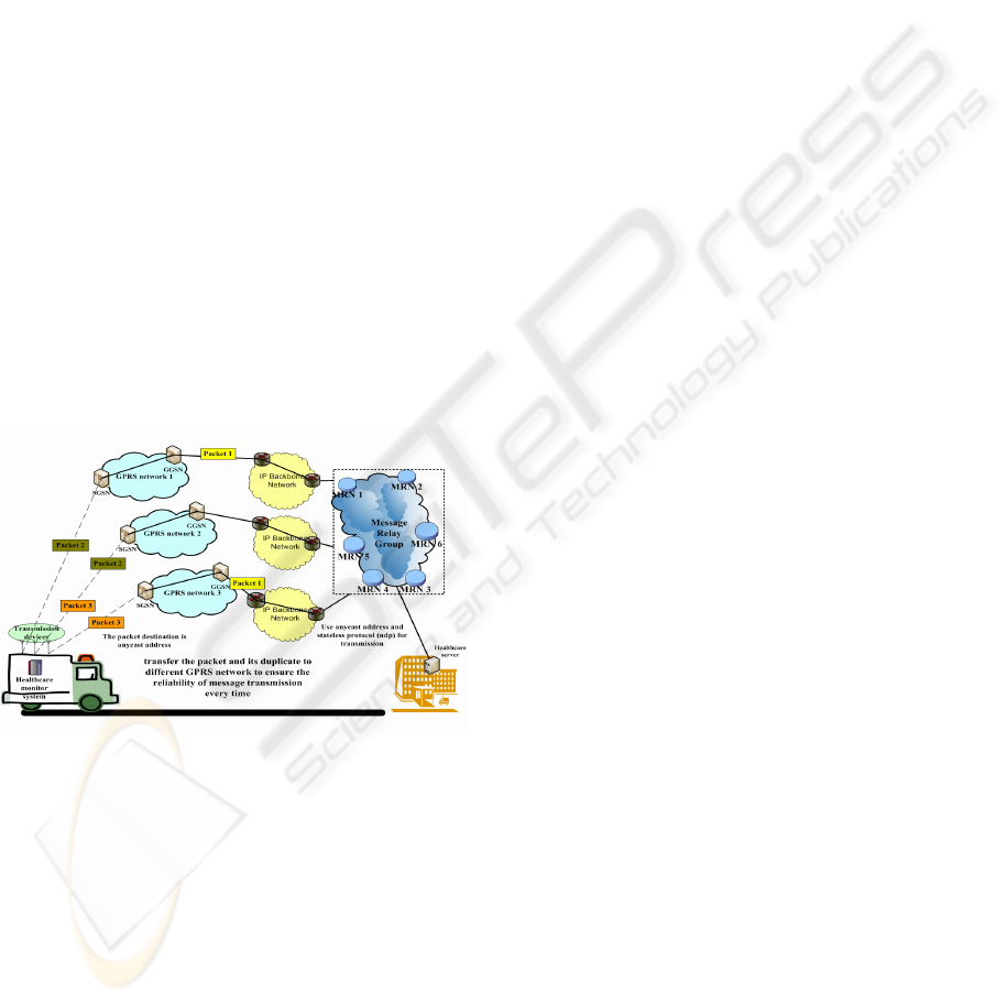
2 SYSTEM ARCHITECTURE
The system architecture of vehicular healthcare
system is shown on Figure 2. Three wireless
transmission devices (TDs) are equipped in the
ambulance, and each device is respectively
connected to GPRS network and also to Internet.
The receiving side, the side with the hospital,
receives the vital sign data from the ambulance via
the network nodes in MRG (Message Relay Group).
MRG is one anycast group, the data is transmitted
with stateless protocol (such as UDP) and the
destination is MRG.
Figure 2: System Architecture of Vehicular Healthcare
System.
Through underlying routing protocols (such as
OSPF, IGP) and using the anycast address as the
destination address, the router can forward the
packet to the “proper” MRN (Message Relay Node).
The “proper” here means the router can find the met
MRN by comparing several parameters, such as the
forwarding load in the MRN, the current left buffer
size, or the living status, etc. MRN periodically
sends the heartbeat messages to update its status to
the nearby router. If none of the heartbeat messages
is found during several period times, the router will
delete the routing information for this MRN in the
routing table. Normally the router can forward the
packet to several MRNs in the MRG. The action to
delete the information in the routing table can avoid
the generation of “black hole” and thus reduce the
possibility of packet loss.
2.1 System Components
Three system components, healthcare monitor
system / MRNs in MRG / healthcare server, are
described in this healthcare system. Healthcare
monitor system is located in the ambulance. And
healthcare server with the mapping MRNs are
located in the hospital side.
2.1.1 Healthcare Monitor System
It is located in the ambulance to collect the vital sign
data from the patients and transmit the data to the
hospital. The system has several vital sign sensors
and three TDs. The reason to use three TDs is to
prevent the data loss, even if one of the devices is
failed. Besides, each time the data and its duplicate
will be sent to the hospital respectively through two
of three TDs and their mapping GPRS paths. This
can reduce the effect of data loss, while the wireless
transmitting signal is weak or having other issues
that prevent the data from reaching the related GPRS
nodes. The duplicated data should be removed in the
application layer of receiving side of the hospital.
Though sending the data with its duplicate at the
same time would waste the transmission bandwidth
in the normal condition, it greatly decreases the
possibility of data loss.
2.1.2 Message Relay Node
It is abbreviated as MRN and is the node to receive
anycast packet, many MRNs exist in the system.
Through underlying routing protocols and the
anycast address, each time the data in the ambulance
can be sent to any and exactly one MRN. This can
avoid the waste of the bandwidth, and the data can
be securely sent to the running MRN.
Router can be aware of MRN’s living status by
periodical receiving the heart-beat messages from
that MRN. And router relies on the MRN decision
parameters, described in the following paragraph,
and coordinates with underlying routing protocol
(such as OSPF, IGP) to select one MRN and
forwards the anycast packet to that MRN.
The MRN decision parameters are,
[ MRN_alive ]
WINSYS 2008 - International Conference on Wireless Information Networks and Systems
220

= 1, means this MRN is alive and it has sent
heart-beat message to the router
= 0, means this MRN is not alive
[ MRN_load ]
= (int) N, the sent packet amount to this MRN
(from the router), it is statistical value.
= 0, if MRN_live = 0, this value will be
cleared to 0.
[ MRN_buffer_usage ]
= (int) M, indicates how many packets are
queued in this MRN, the packet amount value
is sent with heart-beat message from this
MRN.
The MRN selection rule is
(MRN_alive=1) AND Min(MRN_load) AND
Min(MRN_buffer_usage)
Each MRN is connected to healthcare server in
the hospital, and finally healthcare server should
handle the data from the selected MRN.
2.1.3 Healthcare Server
It is used to receive the vital sign data from the
ambulance. Since stateless protocol is used to
transmit the data, call setup procedure is not applied.
While the first data packet comes to the server, one
session table is automatically built to route the
following data packets to the specified line. The
session table contains three columns: source address,
3G’s IMUI data, and the sequence number of
received UDP packet. To have this information in
the server, the extra IMUI data should be added to
the packet while the ambulance is sending the vital
sign data and connects with the application layer of
the hospital.
Since each packet and its duplicate are sent via
two respective paths, one sequence number field
should be added in the payload of UDP. In the
receiving side, the packet-duplication-removal
procedure should be applied in the application layer.
That is, each time the UDP packet (payload) is
received and the sequence number should be
compared with the one in the session table of the
same source address. If the sequence number of the
received UDP is greater than the current sequence
number in the session table, the UDP packet
handling procedure can go on; otherwise, the
received packet is spare and should be dropped.
In this paper, we aim at providing reliable and
stable message transmission while the ambulance is
on the way to the hospital. Therefore it is not the
intension to further describe the received data
handling in the healthcare server.
2.2 System Behaviours
When the patient at the event place was taken care
and moved into the ambulance, the healthcare
monitor system starts its operations and transmits the
data to the hospital, the data includes the vital sign
data (heart-beat rate, blood pressure, etc.) retrieved
from the sensors and the monitoring video view of
the patient. The vocal communication between the
nursing people (in the ambulance) and the hospital
uses normal 2G/3G mobile phone system, and is
totally separated from the healthcare monitor
system.
Each data is divided into several UDP packets
for transmission and the destination address is
MRG’s anycast address. Each UDP packet should
insert the IMUI of the healthcare monitor system
and the sequence number of this UDP packet. The
packets are transmitted through the TDs to the
MRNs (of the same anycast address) of the target
hospital. In the system, three TDs are equipped in
the healthcare monitor system and each time two out
of three TDs are selected to transmit the UDP packet
and its duplicate, thus to enforce the possibility of
successful data transmission. Supposed that the
index number of TD is from 0 to 2, and
i
TD
stands
for transmission device i, each time the selected
transmission devices are
i
TD
and
3mod)1( +i
TD
,where
i= (Sequence_Number) mod 3.
The reason for each time having two TDs with
two separated paths is to make trade-off between the
bandwidth saving and the data loss possibility.
When the UDP packet finally arrived at the specified
MRN, it would judge to accept that packet by
checking the buffer usage of this node. And the
packet should be kept in the FIFO buffer, until it is
finally transmitted to the healthcare server.
3 ANALYSIS
First, the analysis on the packet loss rate of the
system is explained. Second, the hardware cost
comparison using between anycast and multicast to
build up MRG is described.
3.1 Data Loss Probability and
Required Min. MRN Node Number
For easy explanation, Figure 3 is used as the basis of
the system architecture for message reliability
analysis.
A VEHICULAR HEALTHCARE SYSTEM USING ANYCAST AND PERVASIVE COMPUTING - One Pervasive
Computing Application on Mobile Software and Services
221

Figure 3: System Architecture for Message Reliability
Analysis.
Symbol Definitions:
μ
: The summation of traffic load of TDi set (
%)
Ai: The ambulance i
A : The number of Ambulance
A : The routing path loss probability
C: The capacity of each Message Relay Node
j
C
: The buffer used in Message Relay Node
j
R
:
j
CC −=
, the remaining buffer space of
MRN
P: The packet size
1
N
: The total node number in MRG
Figure 3 shows the anycast message forwarding
model. Each time two transmission paths are
selected to deliver the packet and its duplicate.
Assumed that
μ
is the total transmission load in
three TDs of the specified ambulance Ai. The
transmission load is defined as the data transmission
probability in one unit time. It is also assumed that
the transmission load in each ambulance is the same,
and the data loss probability
A
in each path from
TD to MRG has the same amount, but the path
breakdown case is not counted in. The parameter
A
is affected only when the MRN totally fails or when
the buffer is full and no new data can be accepted. C
is the buffer capacity/amount of the specified MRN.
When buffer is fully occupied, the coming packet
will be dropped/lost.
j
R
is the remaining buffer
space of the specified MRN.
1
N
is the total node
number (MRN number) in MRG.
For easy calculation, it is assumed that through
anycast routing the data and its duplicate can arrive
in MRG, and if either the specified data or its
duplicate is failed to arrive, this indicates data loss.
From this assumption, the following two rules are
defined:
(Rule 1)
AD
μ
3
2
Rule 1 is the data loss probability in each
ambulance with 3 TDs and each time 2 data packets
are sent, where
A is the routing path loss
probability.
(Rule 2)
(
)
∑
=
≥
j
N
j
RPPA
1
2
μ
Rule 2 is the condition when data loss occurs in
the whole system. This means when the total
sending packet size is great or equal to the total
remaining buffer size, the data loss occurs.
Under the condition of Rule 2, that is,
(
)
02
1
≥−
∑
= j
N
j
RPPA
μ
, the average routing
path loss probability is
(
)
CPN
RPPA
j
N
j
1
1
2
∑
=
−
=
μ
A
, if further assumed
that the whole MRG with proper underlying routing
protocol can achieve the load-balancing condition,
that is,
β
≅
≅
≅
≅
N
RRR "
21
for MRNs in
MRG. Therefore
(Rule 3)
CCN
A
CN
NA
CPN
PNPA
β
μβμβμ
−=
−
=
−
≅
11
1
1
222
A
Assumed
σ
β
=
C
, is the average remaining
buffer space ratio (percentage), and
1
1
κ
μ
=
CN
A
is the average packet amount coming to each MRN.
Put these two parameters into Rule 1,
(Rule 4)
[]
σκμμ
−≅
1
2
3
2
3
2
DAD
Rule 4 is the system average packet loss
probability, when
(
)
∑
=
≥
j
N
j
RPPA
1
2
μ
.
For easy calculation, Rule 4 is based on the
assumption that when either the packet or its
duplicate is lost, it counts as the data loss. When
Rule 4 is adjusted in the real case and divided by the
sending packet amount, it has the real packet loss
probability:
(Rule 5)
[][]
σκμσκμ
−=−
11
2
3
1
2
3
2
2
1
DDD
For the real data loss probability, Table 1 is
shown to compare with different TD number (how
WINSYS 2008 - International Conference on Wireless Information Networks and Systems
222

many Transmission devices, 1 to 4) allocated in the
ambulance and each time different number of
duplicates (0, 1, or 2) sending to MRG with anycast
routing mechanism.
Table 1: the real data loss probability with TD number and
duplicates.
TD: Transmission Device,
CN
A
1
1
μ
κ
=
,
C
β
σ
=
Observed from Table 1, when [TD = 2] and
[duplicate = 1](Duplicate) the data loss probability is
[]
σκμ
−
1
2
2
1
D
, but if one TD fails, the data loss
probability raises to
[
]
σ
κ
μ
−
1
2D
; Compared with
[TD = 3] and [duplicate = 1](Duplicate), the data
loss probability raises from
[]
σκμ
−
1
2
3
1
D
to
[]
σκμ
−
1
2
2
1
D
, when one TD fails; Compared with
[TD = 4] and [duplicate = 1], the data loss
probability rises from
[]
σκμ
−
1
2
4
1
D
to
[]
σκμ
−
1
2
3
1
D
. Therefore it rises about 50% for [TD
= 2], 17% for [TD = 3], and 8% for [TD = 4]. And
from per-TD viewpoint, it contributes 25% for [TD
=2], 5.6% for [TD = 3], and 2% for [TD = 4]. It is
concluded that with [TD = 3] and compared with
[TD = 2], one additional TD hardware cost is added,
but it greatly reduce the data loss probability. That
is, to trade-off between system stability and
additional hardware cost, [TD = 3] is the optimal
one.
Next, the required minimum MRN node number
is depicted.
Message Relay Node Constraints
Let
C
A
be the expectation value of data loss
probability, under TD = 3,
(Rule 6)
[]
C
ADADD ≤−=
σκμμ
1
2
3
1
3
2
2
1
Put
CN
A
1
1
μ
κ
=
into Rule 6, then
(Rule 7)
μσ
μ
μ
+
≥
C
C
A
N
A
D
3
2
1
N
1
is the needed MRN node number in MRG.
When the network is full loaded and
0=
j
R
for
each MRN, then
0→
σ
, therefore the ratio of MRN
node number vs. |A| (ambulance number) is
(Rule 8)
CA
N
C
A3
2
1
≥
When Rule 8 is applied in real system
configuration and assumed that the data loss
probability for patient video view transmission is
10%,
CA
N
3
20
1
≥
. That is, if MRN node number is
greater than |A|
C
3
20
D
, the overall system data loss
probability is 10%.
Table 2 shows the required minimum MRN node
number list.
Table 2: Required Min. N
1
.
From Table 2, when more TD number is and
each time delivery packet number is less than TD
number, less N
1
is. In Table 1 and Table 2, with TD
= 3 and duplicate = 1(Duplicate) it is the trade-off
result to compete with the required minimum MRN
node number and the low data loss probability.
That’s the system design goal to find the trade-off
point with the minimum installed hardware cost and
the highest transmission stability.
In Table 3, the required minimum MRN node
number to build up stable transmission system under
network fully loaded condition (
0→
σ
) is depicted.
Table 3: The Required Min. N
1
, when
0→
σ
.
3.2 Comparison between Anycast and
Multicast
From section 3.1, the combination of [TD = 3] and
[duplicate = 1] is the trade-off point. In this section,
further comparison using between anycast and
multicast under such combination ([TD = 3] and
Duplicate) is described.
A VEHICULAR HEALTHCARE SYSTEM USING ANYCAST AND PERVASIVE COMPUTING - One Pervasive
Computing Application on Mobile Software and Services
223

Based on Rule 1 and Rule 2 of section 3.1 and
while multicast routing is used, the Rule 9 and Rule
10 are generated,
(Rule 9)
ADD
μ
3
21
2
N
(Rule 10)
(
)
∑
=
≥
j
N
j
RPPAN
12
2
μ
Compared with N
1
of section 3.1 by using
anycast routing algorithm,
2
N
is the required
minimum MRN node number with multicast routing
algorithm. With Rule 9 and Rule 10,
σκ
−=
2
2A
,
where
C
A
μ
κ
=
2
,
C
β
σ
=
.
Follow Rule 7 of section 3.1, the same way of
calculation is proceeded to get the number of
2
N in
Rule 11,
[]
C
N
ADD ≤−
σκμ
2
2
2
3
21
(Rule 11)
C
CA
N
C
A
μ
σμ
2
36
2
−
=
Apply Rule 11 when
0→
σ
, gets
(Rule 12)
12
5.4
3
N
C
A
N
C
==
A
One example with Rule 12, when the average
data loss probability is 10%, buffer size = 10 for
each MRN, and
0→
σ
, they have
10
1
=N
and
45
2
=N
(
12
5.4 NN =
). This is because each data is sent
to all MRNs with multicast routing algorithm and
the buffer of each MRN is soon fully occupied,
therefore the network is full of duplicated data and
the network usage performance is soon reduced. As
the matter of fact, it is the benefit of anycast routing
algorithm to secure the data to be forwarded to
healthcare server, only if any MRN in MRG can
have the data.
4 CONCLUSIONS
The message reliable transmission method between
the ambulance and the hospital with the system
architecture of 3 TDs is proposed in this paper. Each
time two out of three TDs are selected to transmit
the UDP packet and its duplicate. Using anycast, it
doesn’t cause the overload condition as with
multicast, the estimated load difference between
them is
)
2
(
2
N
Ο
. The MRN selection method is
proposed for the router to achieve the load-balancing
condition in MRG.
From the analysis, the combination of [TD = 3]
and [duplicate = 1] is the trade-off point between
system transmission stability and additional
hardware cost. That is, it is the most proper
architecture to set up the stable wireless transmission
between the ambulance and the hospital. Also if one
TD fails under such combination, the data loss
probability rises 17%. Besides, the required
minimum MRN node number for anycast and
multicast is respectively calculated. And the ratio of
N
2
(for multicast) and
1
N
(for anycast) is 4.5. That is,
using anycast and compared with multicast, 4.5 less
MRN node number is required to build MRG and
the same level of data loss probability is achieved.
REFERENCES
Hinden, R., and Derring, S., 1995 “IP Version 6
Addressing Architecture,” RFC 1884.
Jia, W., Xu, G., and Zhao, W., 2000. “Integrated fault-
tolerant multicast and anycast routing algorithm,”
Proceedings of IEE Computer and Digital Techniques.
Dow, C.R., Hsuan, P. and Hwang, S. F., 2006. “Design
and Implementation of Anycast Protocol for Mobile
Ad-hoc Network,” Conference Advanced
Communication Technology.
Metz, C., 2002. “IP anycast point-to-(any) point
communication,” IEEE Internet Computing’, Vol. 6,
Issue 2.
Matsunaga, S., Ata, S., Kitamura, H., Murata, M., 2005.
“Design and Implementation of IPv6 anycast routing
protocol: PIA-SM,” Conference Advanced
Information Networking and Applications.
S. T. Wolfe, S. I. Ahamed, and M. Zulkernine, 2006. “A
trust framework pervasive computing environments,”
IEEE International Conference Computer Systems
and Applications, pp. 312–319.
X. Gu, K. Nahrstedt, and B. Yu, 2004. “Spidernet: An
Integrated Peer-to-Peer Service Composition
Framework,” Proc. 13th IEEE Int’l Symp. High
Performance Distributed Computing (HPDC ’04), pp.
110-119.
M. Hewitt, 2000. “Interpreting the Volume-Outcome
Relationship in the Context of Healthcare Quality:
Workshop Summary,” Inst. Medicine Report,
Washington,D.C..
M. Satyanarayanan, 2001. “Pervasive Computing: Vision
and Challenges”, 2001, IEEE Personal
Communication.
David Garlan, etc al. 2002, “ Project Aura: Toward
Distraction-Free Pervasive Computing”, 2002 IEEE
Pervasive Computing.
WINSYS 2008 - International Conference on Wireless Information Networks and Systems
224
