
PEAK-TO-AVERAGE POWER RATIO OF MULTITONE-HOPPING
CDMA SIGNALS USING FEEDBACK-CONTROLLED HOPPING
PATTERNS
Kazuki Chiba and Masanori Hamamura
Graduate School of Engineering, Kochi University of Technology, 185 Miyanokuchi, Tosayamada, Kochi 782-8502, Japan
Keywords:
CDMA, asynchronous, multipath, feedback, multitone, PAR.
Abstract:
We present the characteristics of peak-to-average power ratio (PAR) for multitone-hopping code-division mul-
tiple access (MH-CDMA) signals using feedback-controlled hopping patterns (FCHPs) (FCHP/MH-CDMA).
In FCHP/MH-CDMA, since each chip of transmitted signals consists of plural tones, energy consumption due
to large PAR may not be negligible at the transmitter. Therefore, it is important to investigate the PAR charac-
teristics of FCHP/MH-CDMA signals. It is shown that limiting the number of tones per chip, and the number
of quantization bits, and clipping on FCHP are effective in reducing the PAR at almost identical bit-error rate
(BER).
1 INTRODUCTION
Intersymbol interference (ISI) and multiple access in-
terference (MAI) are two primary factors that reduce
wireless communication performance. To greatly re-
duce ISI and MAI, feedback-based systems have been
studied. For uplink channels, a method in which a
base station (BS) employs an adaptive filter at a re-
ceiver to produce an analog pseudo-noise (PN) se-
quence, which is assigned to a new user, was pro-
posed (Hamada et al., 1998) in direct-sequence code-
division multiple access (DS-CDMA). Analog PN se-
quences can be orthogonal to each other under ar-
bitrary asynchronous conditions. For a synchronous
DS-CDMA, an iterative construction method that pro-
duces signature sequences using a minimum mean-
squared error (MMSE) filter was proposed (Ulukus
and Yates, 2001). It has been shown that this method
produces a set of Welch bound equality (WBE) se-
quences (Welch, 1994; Rupf and Massey, 1994) using
an MMSE filter whose size is identical to the length
of the signature sequence. In contrast, we have pro-
posed another DS-CDMA using feedback-controlled
spreading sequences (FCSS/DS-CDMA) (Miyatake
et al., 2004; Miyatake et al., 2008). In the FCSS/DS-
CDMA, the receiver employs an adaptive filter whose
size is larger than the length of the signature sequence
and returns part of the filter coefficients to a trans-
mitter. It has been shown that this method yields su-
perior performance in terms of bit-error rate (BER)
over time-invariant multipath channels. Furthermore,
we have proposed multitone-hopping CDMA (MH-
CDMA) using a feedback-controlled hopping pat-
tern (FCHP) (FCHP/MH-CDMA), which combines
the frequency-hopping CDMA (FH-CDMA) with the
FCSS/DS-CDMA, to increase signal-to-interference
plus noise ratio (SINR) (Chiba and Hamamura, 2007).
Each receiver of the FCHP/MH-CDMA is composed
of a time-frequency,two-dimensional, adaptivefinite-
duration impulse response (FIR) filter, which is larger
than the hopping pattern. The receiver returns part of
the filter coefficients to a transmitter. Since the sig-
nals transmitted in the FCHP/MH-CDMA consist of
FCHP-coded multiple frequency tones, which usually
result in large peak-to-average power ratio (PAR) that
increases energy consumption at the transmitter, it is
important to investigate the characteristics of PAR.
In this paper, the impact of limiting the number of
tones, the number of quantization bits, and tone level
on PAR and BER is clarified.
2 FCHP/MH-CDMA
2.1 Transmitter
We assume uplink multiple access illustrated in Fig.
1.
A signal received at the position of BS can be
145
Chiba K. and Hamamura M. (2008).
PEAK-TO-AVERAGE POWER RATIO OF MULTITONE-HOPPING CDMA SIGNALS USING FEEDBACK-CONTROLLED HOPPING PATTERNS.
In Proceedings of the International Conference on Wireless Information Networks and Systems, pages 145-150
DOI: 10.5220/0002023401450150
Copyright
c
SciTePress
Channel
Receiver for kth signal
h
k
(
τ
)
AWGN
Feedback (Time interval T
f
)
Transmitter for kth signal
T
s
Message
symbol
p
k,1,1
p
k,1,2
...
p
k,1,M
p
k,2,1
p
k,2,2
...
p
k,2,M
p
k,L,1
p
k,L,2
...
p
k,L,M
...
...
...
...
Frequency
synthesizer
c
k
(t)
b
k
(n)
d
k
(n)
d
k
(n-1)
s
k
(t)
r(t)
+
-
T
c
Σ
T
s
*
Adaptive
algorithm
Message
symbol
b
k
(n)
d
k
(n)
d
k
*
(n-1)
^
~
~
~
d
k
(n)
e
k
(n)
Σ
w
*
k,1,L+α
w
*
k,1,L+1
w
*
k,1,L
w
*
k,1,2
w
*
k,1,1
T
c
T
c
T
c
Σ
w
*
k,2,L+α
w
*
k,2,L+1
w
*
k,2,L
w
*
k,2,2
w
*
k,2,1
T
c
T
c
Σ
w
*
k,M,L+α
w
*
k,M,L+1
w
*
k,M,L
w
*
k,M,2
w
*
k,M,1
T
c
T
c
T
c
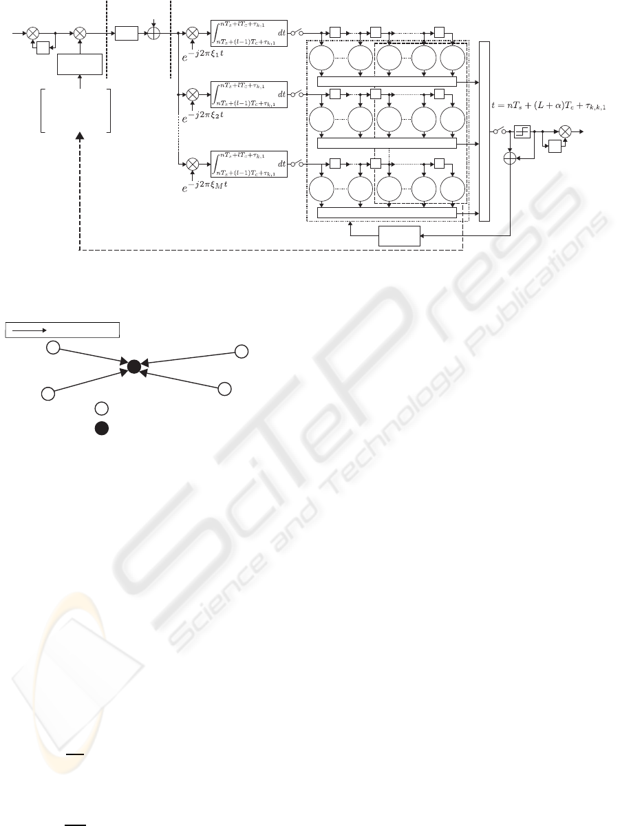
Figure 2: Transmitter and receiver for kth signal.
Tx
1
Tx
2
BS
Tx
k
Tx
K
Transmission
Tx
k
: Transmitter for kth signal
BS: Base station
Figure 1: Uplink multiple access (asynchronous transmis-
sion).
modeled as a sum of K signals that are independently
transmitted through distinct channels. The transmitter
and receiver for the kth signal (k = 1, 2,··· ,K) of the
FCHP/MH-CDMA are shown in Fig. 2.
The signature waveform c
k
(t) for the kth signal is
given by
c
k
(t) =
L
∑
l=1
a
k,l
(t −(l −1)T
c
), (1)
where a
k,l
(t)(0 < t < T
c
;T
c
[s] is the chip duration) is
the lth chip waveform (l = 1,2, ···,L) for c
k
(t), given
by
a
k,l
(t) = g(t)
M
∑
m=1
p
k,l,m
e
j2πξ
m
t
, (2)
where j =
√
−1, p
k,l,m
(= A
k,l,m
e
jφ
k,l,m
) is the com-
plex amplitude of the mth tone of frequency ξ
m
[Hz]
(m = 1,2,··· ,M) for the lth chip of c
k
(t), and g(t) =
{1(0 < t < T
c
),0(otherwise)}. In this paper, we
choose ξ
m
=
m−1
T
c
.
Let P
k
be an L×M matrix that contains p
k,l,m
such
that
P
k
=
p
k,1,1
p
k,1,2
··· p
k,1,M
p
k,2,1
p
k,2,2
··· p
k,2,M
.
.
.
.
.
.
.
.
.
.
.
.
p
k,L,1
p
k,L,2
··· p
k,L,M
. (3)
The matrix P
k
is the hopping pattern for the kth signal.
The kth signal transmitted by the transmitter is
given by
s
k
(t) =
∞
∑
n=0
d
k
(n)c
k
(t −nT
s
), (4)
where d
k
(n) = b
k
(n)d
k
(n −1) is a differentially en-
coded complex symbol transmitted in nT
s
< t < (n+
1)T
s
(n = 0, 1,···), b
k
(n) is a complex message sym-
bol, and T
s
[s] is the symbol duration (T
s
= LT
c
).
In this paper, we assume that b
k
(n) is a quaternary
phase-shift keying (QPSK) symbol.
2.2 Channel
Let h
k
(t) be the impulse response of the channel
through which the kth signal (k = 1,2,··· ,K) is trans-
mitted to the BS, given by
h
k
(t) =
I
k
∑
i=1
h
k,i
δ(t −τ
k,i
), (5)
where h
k,i
(= |h
k,i
|e
jθ
k,i
) is the complex gain constant
for the ith path of the channel, τ
k,i
(0 ≤τ
k,i
< T
s
) is the
delay for the ith path, and I
k
is the number of paths of
the channel.
The received signal r(t) at the position of the
WINSYS 2008 - International Conference on Wireless Information Networks and Systems
146

BS is given by
r(t) =
K
∑
k=1
(s
k
(t) ∗h
k
(t)) + n(t) (6)
=
K
∑
k=1
∞
∑
n=0
I
k
∑
i=1
h
k,i
d
k
(n)c
k
(t −nT
s
−τ
k,i
) + n(t), (7)
where n(t) is an additive white Gaussian noise
(AWGN) with a double-sided power spectral density
of N
0
/2 [W/Hz].
2.3 Receiver
The receiver for the kth signal is composed of the
adaptive FIR filter, which has (L + α) ×M complex
weights (0 ≤ α ≤ L). Let W
k
be an (L+ α) ×M ma-
trix whose (l, m)th entry is the complex weight w
k,l,m
of the receiver. The weight matrix W
k
is updated
by an adaptive algorithm. In this paper, we adopt
a normalized least-mean-square (N-LMS) algorithm
(Haykin, 1996). For simplicity, we assume that the re-
ceiver for the kth signal is synchronized with the first
path of the channel h
k
(t). The kth receiver obtains
discrete-time samples of every frequency and chip
from the received signal r
k
(t). The mth frequency
component r
k,l,m
, detected at t = nT
s
+ lT
c
+ τ
k,1
(l =
1,2,··· , L+ α), is given by
r
k,l,m
(n) =
Z
nT
s
+lT
c
+τ
k,1
nT
s
+(l−1)T
c
+τ
k,1
r
k
(t)e
−j
2π(m−1)
T
c
t
dt. (8)
We define the (L+ α)×M matrix R
k
(n) that contains
the samples detected in nT
s
+ τ
k,1
< t < nT
s
+ (L +
α)T
c
+ τ
k,1
as
R
k
(n) =
r
k,1,1
(n) r
k,1,2
(n) ··· r
k,1,M
(n)
r
k,2,1
(n) r
k,2,2
(n) ··· r
k,2,M
(n)
.
.
.
.
.
.
.
.
.
.
.
.
r
k,L,1
(n) r
k,L,2
(n) ··· r
k,L,M
(n)
r
k,1,1
(n+ 1) r
k,1,2
(n+ 1) ··· r
k,1,M
(n+ 1)
r
k,2,1
(n+ 1) r
k,2,2
(n+ 1) ··· r
k,2,M
(n+ 1)
.
.
.
.
.
.
.
.
.
.
.
.
r
k,α,1
(n+ 1) r
k,α,2
(n+ 1) ··· r
k,α,M
(n+ 1)
.
(9)
The FIR filter output
ˆ
d
k
(n) can be represented as
ˆ
d
k
(n) = tr[W
H
k
(n)R
k
(n)], (10)
where the superscript
H
denotes the complex conju-
gate and transpose of the matrix, and tr[ ·] denotes the
trace of the matrix. To recover the message symbol
b
k
(n), the receiver determines the sign for the real and
imaginary parts of
ˆ
d
k
(n), such that
˜
d
k
(n) = sgn[Re[
ˆ
d
k
(n)]] + jsgn[Im[
ˆ
d
k
(n)]], (11)
where sgn[ ·] is the signum function, Re[ ·] is the real
part of the complex value, and Im[ ·] is the imaginary
part of the complex value. Using
˜
d
k
(n), the estimate
˜
b
k
(n) of the complex message symbol b
k
(n) is given
by
˜
b
k
(n) =
˜
d
k
(n)
˜
d
∗
k
(n−1) (12)
= (sgn[Re[
ˆ
d
k
(n)]] + jsgn[Im[
ˆ
d
k
(n)]])
×(sgn[Re[
ˆ
d
k
(n−1)]] − jsgn[Im[
ˆ
d
k
(n−1)]]), (13)
where the superscript
∗
denotes the complex conju-
gate.
The weight matrix W
k
(n) is updated as
W
k
(n+ 1) = W
k
(n) +
µ
tr[R
H
k
(n)R
k
(n)]
R
k
(n)e
∗
k
(n),
(14)
where µ is the step size parameter and e
k
(n) is
e
k
(n) =
˜
d
k
(n) −tr[W
H
k
(n)R
k
(n)]. (15)
In this paper, the initial value W
k
(0) of the weight
matrix W
k
(n) for the kth receiver is chosen to be a set
of weights that consists of the corresponding initial
hopping pattern P
k
(0) and the zero matrix 0
α×M
of
size α×M, that is,
W
k
(0) = [P
T
k
(0) 0
T
α×M
]
T
, (16)
where the superscript
T
denotes the transpose of the
matrix.
2.4 Feedback
Part of the FIR filter weights of the receiver for the
kth signal are fed back to the corresponding trans-
mitter, in which they are used as an updated ver-
sion of the hopping pattern P
k
. In this paper, no de-
lay time and no error for the feedback are assumed.
Therefore, the hopping pattern P
k
(λ) updated at t =
λT
f
+∆
k
+αT
c
+τ
k,1
(λ = 1,2,··· ,N
f
; N
f
is the num-
ber of iterations of the feedback, T
f
is the feedback
time interval, ∆
k
is the preassigned offset of the feed-
back timing (0 ≤∆
k
< T
f
)) is represented as
P
k
(λ)
,
p
k,1,1
(λ) p
k,1,2
(λ) ··· p
k,1,M
(λ)
p
k,2,1
(λ) p
k,2,2
(λ) ··· p
k,2,M
(λ)
.
.
.
.
.
.
.
.
.
.
.
.
p
k,L,1
(λ) p
k,L,2
(λ) ··· p
k,L,M
(λ)
(17)
PEAK-TO-AVERAGE POWER RATIO OF MULTITONE-HOPPING CDMA SIGNALS USING
FEEDBACK-CONTROLLED HOPPING PATTERNS
147

=
w
k,1,1
( ˆn
k
) w
k,1,2
( ˆn
k
) ··· w
k,1,M
( ˆn
k
)
w
k,2,1
( ˆn
k
) w
k,2,2
( ˆn
k
) ··· w
k,2,M
( ˆn
k
)
.
.
.
.
.
.
.
.
.
.
.
.
w
k,L,1
( ˆn
k
) w
k,L,2
( ˆn
k
) ··· w
k,L,M
( ˆn
k
)
,
(18)
where ˆn
k
, ⌊(λT
f
+ ∆
k
+ αT
c
+ τ
k,1
)/T
s
⌋ (⌊X ⌋ is the
maximum positive integer less than or equal to X ).
The FIR filter receiver produces the filter weights that
are the MMSE solution to the reference
˜
d
k
(n). As a
result, the FIR filter receiver obtains the minimum ISI
and MAI for the present received signals.
2.4.1 Limited Number of Tones
The hopping pattern generates multicarrier signals at
the transmitter. In general, the PAR of multicarrier
signals is larger than that of single carrier signals.
Therefore, we discuss the impact of the limited num-
ber of tones per chip. In this paper, we consider
the FCHP/MH-CDMA signals consisting of M
limited
(≤ M) tones per chip. This can be realized by the
hopping pattern P
k
(λ) every row of which contains
M
limited
nonzero elements and M −M
limited
zero ele-
ments.
2.4.2 Quantization
Since the FIR filter weights take continuous values,
the updated version of the hopping pattern contains
elements that have continuous values. Therefore, the
receiver requires quantization for feedback. We em-
ploy uniform quantization. Let a
(max)
k
(λ) be the max-
imum absolute value of the real and imaginary parts
in all the elements of the hopping pattern P
k
(λ), that
is,
a
(max)
k
(λ) = max
l,m
{|Re[p
k,l,m
]|,|Im[p
k,l,m
]|}. (19)
The elements p
(quantized)
k,l,m
of a quantized hopping pat-
tern are given by
p
(quantized)
k,l,m
=
⌈Re[ρ
k,l,m
(λ)]⌉+ j⌈Im[ρ
k,l,m
(λ)]⌉ (0 ≤ φ
k,l,m
<
π
2
)
⌊Re[ρ
k,l,m
(λ)]⌋+ j⌈Im[ρ
k,l,m
(λ)]⌉ (
π
2
≤ φ
k,l,m
<π)
⌈Re[ρ
k,l,m
(λ)]⌉+ j⌊Im[ρ
k,l,m
(λ)]⌋ (π ≤ φ
k,l,m
<
3π
4
)
⌊Re[ρ
k,l,m
(λ)]⌋+ j⌊Im[ρ
k,l,m
(λ)]⌋ (
3π
4
≤φ
k,l,m
<2π)
,
(20)
where ⌈X ⌉ is the minimum integer greater than or
equal to X , and
ρ
k,l,m
(λ) =
p
k,l,m
(λ)
a
(max)
k
(λ)
2
q−1
, (21)
and q is the number of quantization bits.
2.4.3 Clipping
In general, every chip of FCHP has a different energy.
This may cause a large variation in the amplitude of
the FCHP/MH-CDMA signal, which results in a large
PAR. Therefore, to reduce this variation, we employ a
technique of clipping a hoppingpattern. Let A
(clipping)
be a clipping level, given by
A
(clipping)
=
q
tr[P
H
k
(λ)P
k
(λ)]
L
β, (22)
where β is a real constant. Using A
(clipping)
, the values
p
(clipped)
k,l,m
of elements for the clipped hopping pattern
are given by
p
(clipped)
k,l,m
(λ) =
p
k,l,m
(λ) (|p
k,l,m
| ≤ A
(clipping)
)
A
(clipping)
e
jφ
k,l,m
(|p
k,l,m
| > A
(clipping)
)
. (23)
3 PERFORMANCE EVALUATION
3.1 Specifications
3.1.1 Multipath Model
We assume a six-path model (i.e., I
k
= 6 for all
k
′
s) that has a delay profile of exponential de-
cay, where the relative intensities of |h
k,i
| are
20log
10
(|h
k,i+1
|/|h
k,i
|) = −3dB (i = 1,2,··· ,I
k
−1),
the path delays τ
k,i
are τ
k,i+1
−τ
k,i
=
L+1
16
T
c
(≈
1
16
T
s
for L = 7), and τ
k,1
(for all k
′
s) and θ
k,i
(for all k
′
s and
i
′
s) are mutually statistically independent, uniformly
distributed random variables in the intervals of [0,T
s
)
and [0,2π), respectively.
3.1.2 Other Specifications
The FCHP/MH-CDMA requiresan initial training pe-
riod during which the receiver returns part of the fil-
ter weights to the corresponding transmitter to con-
struct a suitable hopping pattern for the current chan-
nel state. In this paper, we define the initial training
period as t < (N
f
+ 1)T
f
+ ∆
k
+ τ
k,1
and discuss the
BER performance in the steady period, which is de-
fined as the period after the initial training period, that
is, t ≥ (N
f
+ 1)T
f
+ ∆
k
+ τ
k,1
. In the steady period,
only the filter weights are updated at the receiver (i.e.,
no feedback). We assume that the reference
˜
d
k
(n)
used for updating the filter weights is
˜
d
k
(n) = d
k
(n)
during the initial training period, which implies that
the receiverhas prior knowledgeof the pilot data sym-
bols used for the initial training. Since both BER and
WINSYS 2008 - International Conference on Wireless Information Networks and Systems
148
PAR slightly depend on the randomly chosen values
of τ
k,1
and θ
k,i
, all plots show the average of five sim-
ulation trials. Other common specifications are listed
in Table 1.
Table 1: Common specifications.
Data Differentially encoded QPSK
E
b
/N
0
9.9dB
L 7
α 7
M 8
T
f
10
4
T
s
N
f
10
∆
k
Uniform distribution in [0,T
f
)
Adaptive algorithm N-LMS (µ = 0.1)
3.2 Simulation Results
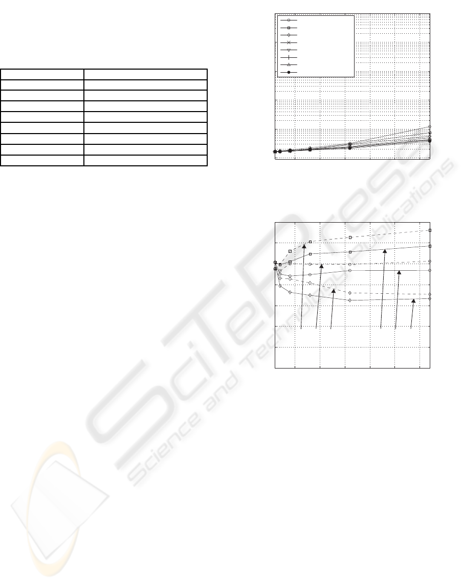
3.2.1 Par Vs Limited Number of Tones
It is easily expected that a small number of tones
yields a small PAR; however, this causes a large BER.
Therefore, we evaluate both BER and PAR. Figure
3(a) shows the characteristics of BER vs the number
of active signals, K, for different limited numbers of
tones, M
limited
.
It is observed that the BER values for 4 ≤
M
limited
≤ 7 are almost identical to those for
M
limited
= 8(= M). Figure 3(b) shows a comparison
of the PAR for M
limited
= 4 with M
limited
= 8. It is seen
that M
limited
= 4 reduces the PAR for M
limited
= 8.
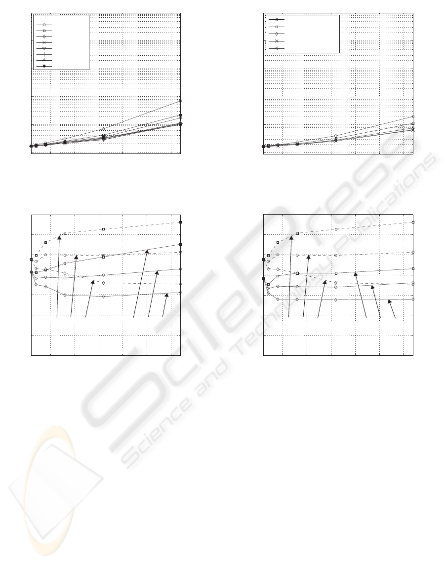
3.2.2 Par Vs Number of Quantization Bits
Figure 4(a) shows the characteristics of BER vs the
number of active signals, K, for different numbers of
quantization bits, q. M
limited
= 4 is assumed. It is
observed from Fig. 4(a) that the BER values are iden-
tical for q ≥ 4. Figure 4(b) shows the characteristics
of PAR for q = 4 and M
limited
= 4, from which the
effectiveness of PAR reduction can be confirmed.
3.2.3 Clipping
Figure 5(a) shows the characteristics of BER vs the
number of active signals, K, for different clipping lev-
els, β.
M
limited
= 4 and q = 4 are assumed. It is observed
from Fig. 5(a) that the BER values are identical for
β ≥ 1.5. Figure 5(b) shows the characteristics of PAR
for β = 1.5, M
limited
= 4 and q = 4, from which the ef-
fectiveness of PAR reduction can be confirmed. Note
that the technique of clipping discussed in this section
does not cause any inter-tone interference, because
5 10 15 20 25 301 32
10
-5
10
-4
10
-3
10
-2
10
-1
10
0
M
limitted
= 1 tone
M
limitted
= 2 tones
M
limitted
= 3 tones
M
limitted
= 4 tones
M
limitted
= 5 tones
M
limitted
= 6 tones
M
limitted
= 7 tones
M
limitted
= 8 tones
Bit-Error Rate
Number of Active Signals, K
5 10 15 20 25 301 32
0
2
4
6
8
10
12
14
Average PAR
Maximum PAR
Minimum PAR
PAR [dB]
Number of Active Signals, K
(a) BER vs limited number of tones (no quantization,
noclipping).
(b) PAR vs limited number of tones (no quantization,
no clipping).
(8 tones)
Average PAR
Maximum PAR
Minimum PAR
(4 tones)
Figure 3: Impact of limited number of tones.
only the elements of hopping pattern are clipped, that
is, waveforms are not clipped.
4 CONCLUSIONS
In this paper, we have investigated the PAR of
FCHP/MH-CDMA signals and shown that tone selec-
tion by limiting the number of tones per chip, quan-
tization for reducing the overhead for feedback, and
clipping an FCHP are effective in reducing the PAR.
PEAK-TO-AVERAGE POWER RATIO OF MULTITONE-HOPPING CDMA SIGNALS USING
FEEDBACK-CONTROLLED HOPPING PATTERNS
149
5 10 15 20 25 301 32
0
2
4
6
8
10
12
14
5 3210 15 20 25 301
10
-5
10
-4
10
-3
10
-2
10
-1
10
0
no quantization
1 bit
2 bits
3 bits
4 bits
5 bits
6 bits
7 bits
8 bits
Bit Error Rate
Number of Active Signals, K
(a) BER vs number of quantization bits (M
limited
= 4
tones, no clipping).
(b) PAR vs number of quantization bits (no clipping).
Ave
rage PAR
Maximum PAR
Minimum PAR
(8 tones, no quantization)
Average PAR
Maximum PAR
Minimum PAR
(4 tones, 4bits quantization)
PAR [dB]
Number of Active Signals, K
Figure 4: Impact of number of quantization bits.
REFERENCES
Chiba, K. and Hamamura, M. (2007). Performance of
multitone hopping CDMA using feedback-controlled
hopping pattern over multipath channel. In IEICE
Technical Report, volume WBS2007-12. IEICE.
Hamada, S., Hamamura, M., Suzuki, H., and Tachikawa,
S. (1998). A proposed DS/CDMA system using ana-
log PN sequences produced by adaptive filters. IEICE
Trans. Fundamentals, E81-A(11):2261–2268.
Haykin, S. (1996). Adaptive Filter Theory. Prentice Hall,
New Jersey, 3rd edition.
Miyatake, T., Chiba, K., Hamamura, M., and Tachikawa, S.
(2008). Asynchronous, decentralized DS-CDMA us-
ing feedback-controlled spreading sequences for time-
dispersive channels. IEICE Trans. Commun., E91-
B(1):53–61.
5 10 15 20 25 301 32
10
-5
10
-4
10
-3
10
-2
10
-1
10
0
β = 0.5
β = 1.0
β = 1.5
β = 2.0
β = ∞ (no clipping)
Bit-Error Rate
Number of Active Signals, K
5 10 15 20 25 301 32
0
2
4
6
8
10
12
14
Number of Active Signals, K
PAR [dB]
(a) BER vs clipping level (M
limited
= 4 tones, q = 4
bits).
(b) PAR vs clipping level.
Ave
rage PAR
Maximum PAR
Minimum PAR
(8 tones, no quantization,
no clipping)
Average PAR
Maximum PAR
Minimum PAR
(4 tones, 4bits quantization,
β = 2.0)
Figure 5: Impact of clipping.
Miyatake, T., Hamamura, M., and Tachikawa, S. (2004).
Performance of DS/SS system using feedback con-
trolled spreading sequence over a multipath channel.
pages 567–571. Proc. ISITA2004. Parma.
Rupf, M. and Massey, J. L. (1994). Optimum sequence mul-
tisets for synchronous code-division multiple-access
channels. IEEE Trans. Inform. Theory, 40(4):1261–
1266.
Ulukus, S. and Yates, R. D. (2001). Iterative construc-
tions of optimum signature sequence sets in syn-
chronous CDMA systems. IEEE Trans. Inform. The-
ory, 47(5):1989–1998.
Welch, L. R. (1994). Lower bounds on the maximum cross
correlation of signals. IEEE Trans. Inform. Theory,
20(3):397–399.
WINSYS 2008 - International Conference on Wireless Information Networks and Systems
150
