
FRAME LENGTH DESIGN FOR MULTIBAND-OFDM ULTRA
WIDEBAND NETWORKS
Liaoyuan Zeng, Eduardo Cano, Michael Barry and Sean McGrath
Wireless Access Research Centre, University of Limerick, Limerick, Ireland
Keywords:
Ultra Wideband, Prioritized Contention Access, Saturation Throughput, Frame Length, Bit Error Rate, Multi-
band Orthogonal Frequency Division Multiplexing, Rayleigh Fading.
Abstract:
A new design of the optimal MAC frame payload length for maximizing the saturation throughput of the
Prioritized Contention Access (PCA) of the WiMedia Ultra Wideband (UWB) standard in Rayleigh fading
channel is presented in this paper. In the WiMedia standard, the Multiband Orthogonal Frequency Division
Multiplexing (MB-OFDM) is used as the basic physical scheme. The proposed design is based on the through-
put analysis carried out by extending an original Enhanced Distributed Contention Access (EDCA) model for
802.11e into the MB-OFDM UWB protocol. The extended model considers the effects of the bit error rate, the
transmission opportunity limits, and the uniqueness of WiMedia MAC timing structure. The station through-
put is sensitive to the frame payload length, and the optimal frame payload length increases exponentially
when the value of the signal-to-noise ratio is higher. The optimal payload length is independent of the number
of the active stations, data rate, and the priority of the Access Categories (ACs). Therefore, a station can
dynamically adapt the length of the transmitted frame in the MAC layer according to the current SNR level so
as to maximize its saturation throughput in the MB-OFDM UWB network.
1 INTRODUCTION
Ultra wideband (UWB) technology is an emerging
candidate for short-range wireless communications
and precise location systems (Win and Scholtz, 1988).
The Federal Communication Commission (FCC) de-
fines UWB signal as a wireless transmission in the un-
licensed 3.1-10.6 GHz band that possesses a -10 dB
bandwidth greater than 20% of its centre frequency
or one exceeding 500 MHz (Federal Communications
Commission, 2002). In recent years, extensive re-
search work in both academia and industry has been
focused on the design and implementation of UWB
systems due to its ability to provide very high data
rate with low power and low cost for Personal Com-
puting (PC), Consumer Electronics (CE), and mo-
bile applications in a short-range. In 2002, the IEEE
802.15.3a Task Group was initially formed planning
to standardize the specifications of an UWB Physi-
cal layer (PHY) for the high-speed Wireless Personal
Area Networks (WPAN). One of the two leading PHY
specifications is Multiband Orthogonal Frequency Di-
vision Multiplexing (MB-OFDM) UWB, supported
by WiMedia Alliance (WiMedia Alliance, 2008) who
later standardized its own Medium Access Control
(MAC) specification based on MB-OFDM UWB (Ba-
tra et al., 2003).
The WiMedia MAC protocol (ECMA Interna-
tional, 2005) is implemented in a distributed man-
ner, implying that no central coordinator is used for
network management. The beacon frame is trans-
mitted by every station for synchronization, network
topology control, and channel access coordination.
This distributed architecture brings high reliability
and better mobility than the centralized networks.
Other advantages include the ease of system design,
performance evaluation, and simulation (Vishnevsky
et al., 2008). This MAC-PHY specification was then
adopted by ECMA (ECMA International, 2005) as
a standard for short-range wireless communications,
and has already received intensive support from the
global industry.
In the WiMedia MAC protocol, two fundamental
medium access mechanisms are defined, one is the
contention based Prioritized Channel Access (PCA),
and the other one is the reservation based Distributed
Reservation Protocol (DRP). PCA is designed for
network scalability and is very similar to the En-
113
Zeng L., Cano E., Barry M. and McGrath S. (2008).
FRAME LENGTH DESIGN FOR MULTIBAND-OFDM ULTRA WIDEBAND NETWORKS.
In Proceedings of the International Conference on Wireless Information Networks and Systems, pages 113-120
DOI: 10.5220/0002024501130120
Copyright
c
SciTePress

hanced Distributed Channel Access (EDCA) mech-
anism used in the IEEE 802.11e systems (IEEE Std.
802.11e, 2003). In PCA, four priorities are assigned
to four types of applications called Access Categories
(ACs, i.e. backgroud, best effort, video, and voice).
Higher prioritized AC has higher probability to ac-
cess the channel due to shorter backoff period. Ev-
ery AC has a pre-defined transmission period, known
as Transmission Opportunity (TXOP). DRP is used
mainly for isochronous traffic, by which network sta-
tions are allowed to arbitrarily reserve a period of time
for exclusive data transmission.
In comparison with other MACs, the WiMedia
MAC has not received a lot of attention in the litera-
ture. In (Zang et al., 2005), the theoretical maximum
throughput of the WiMedia MAC is evaluated for a
error-free wireless channel. In (Wong et al., 2007),
a three dimensional discrete-time Markov chain was
used to analyze the saturation throughput of the PCA
schemes by employing simplified DRP rules and fixed
Bit Error Rate (BER). The effects of the TXOP limi-
tation and the backoff counter freezing were not con-
sidered in the paper. A packet aggregation and re-
transmission MAC scheme for the error-prone high-
data-rate UWB Ad Hoc networks was proposed in (Lu
et al., 2007). The control procedure of the proposed
MAC scheme is based on the IEEE 802.11 (IEEE Std.
802.11, 1999) model.
This paper focuses on the design of the optimal
MAC frame payload length (frame length) for max-
imizing the saturation throughput of the WiMedia
PCA scheme over the Rayleigh fading channel. A
large frame length tends to result in high Packet Er-
ror Rate (PER), and a small one usually leads to
high transmission overhead for the system. Both of
these situations will decrease the saturation through-
put. Therefore, there is an optimal frame length value
for the system to achieve the maximum throughput.
The frame length adaptive function can be imple-
mented in the MAC layer.
The proposed design is based on the saturation
throughput analysis. Since the PCA is very similar
to the extensively studied EDCA mechanism (Xiao,
2005)(Deng and Chang, 1999)(Mangold et al., 2002),
the throughput analysis is carried out by extending
the EDCA model proposed in (Kong et al., 2004) for
IEEE 802.11e into the UWB region. In (Kong et al.,
2004), an analytical model of the EDCA scheme us-
ing a three-dimensional discrete time Markov chain
was developed. This model accurately reflects the pri-
oritized backoff procedures by considering the back-
off deferring due to other station’s transmission, and
different length of the backoff procedure, as well as
the contention between different ACs within a station.
Figure 1: The format of PCLP.
This original model is extended by taking into account
a BER model based on the Rayleigh fading channel,
TXOP limitations, and the uniqueness of WiMedia
MAC timing structure. The new model is more ac-
curate for accomplishing the WiMedia MAC protocol
specifications.
The paper is organized as follows. In section 2 Wi-
Media PHY and MAC protocol is reviewed. In sec-
tion 3 the PCA’s saturation throughput performance
is analyzed following the introduction to the extended
analytical model, and the optimal frame length design
is provided . The numerical results analysis is carried
out in section 4. Concluding remarks are given in Sec-
tion 5.
2 WIMEDIA MAC AND PHY
PROTOCOL OVERVIEW
This section provides a review of the WiMedia PHY
and MAC specifications, and specifically focuses on
the introduction of the WiMedia PCA schemes.
2.1 WiMedia MB-OFDM PHY
In the WiMedia PHY protocol, the UWB bandwidth
is divided into fourteen sub-bands, each with 528
MHz. The OFDM symbols are allocated to each sub-
bands for transmission. In each of the sub-band, a to-
tal number of 122 sub-carriers are used for data trans-
mission.
Data packets coming from the MAC layer to the
PHY are converged into Physical Layer Convergence
Protocol (PLCP) frame. The frame consists of a
PLCP preamble, a PLCP header and a frame payload,
as depicted in Figure 1. The preamble and header
serve as aids in the demodulation, decoding, and de-
livery of the frame payload at the receiver. It is as-
sumed in this manuscript that no bit error will oc-
cur within the PLCP preamble and header since they
are transmitted at the lowest data rate (39.4 Mbps) in
small sizes. MAC frame payload is formatted into
PLCP frame payload which can be transmitted at the
data rate from 53.3 to 480 Mbps.
Before a transmission, the PLCP header and pay-
load are first coded using punctured convolutional
code. Next, the data stream is interleaved and then
mapped using either Quadrature Phase Shift Keying
WINSYS 2008 - International Conference on Wireless Information Networks and Systems
114

Figure 2: WiMedia MAC superframe structure.
(QPSK) (data rate≤200 Mbps) or Dual-Carrier Mod-
ulation (DCM) (data rate>200 Mbps). Subsequently,
each mapped symbol is modulated into a OFDM
symbol by the OFDM modulator using Inverse Fast
Fourier Transform (IFFT). Finally, the OFDM sym-
bols are mapped onto the corresponding sub-carriers
according to the time-frequency code and transmitted
into the UWB wireless channel.
Rayleigh fading is used in the analysis to model
the UWB channel fading (Lai et al., 2007). Thus, the
average BER of the transmitted data can be expressed
as
P
BER
= 1/2[1 −
p
γ/(1 + γ)], (1)
where γ is the average SNR per bit.
Since the convolutional coding process enables
the receiver to correct several bit errors of the data
stream transmitted over the fading channel, the value
of the PER can be calculated as (Taub and Schilling,
1986)
p
0
e
=
L
c
∑
i=n+1
L
c
n + 1
P
(n+1)
BER
(1 − P
BER
)
(L
c
−n−1)
, (2)
where L
c
is the length of the convolutional coded pay-
load, and n is the maximum number of bit that can be
corrected by the convolutional coding.
For simplicity, the value of the PER is approxi-
mated as
p
e
= 1 − (1 − P
BER
)
8L
, (3)
where L is the length of the payload in bytes. It can be
observed that p
e
≥ p
0
e
when the payload size is large.
So, p
e
represents an upper bound expression for the
PER.
2.2 WiMedia MAC
The basic time division of the WiMedia MAC is su-
perframe. It contains a variable length beacon period
and a data transmission period. A superframe com-
prises 256 Medium Access Slots (MASs) of 256 µs
each. The structure of a superframe is shown in Fig-
ure 2.
Every superframe starts with a beacon period
(BP) during which the beacon frames are mandatorily
transmitted by each station to provide timing refer-
ence, carry control information, and broadcast chan-
nel reservation information for the entire superframe.
A BP consists of up to 96 beacon slots (BSs), each
lasts 85 µs and could only be exclusively occupied by
one station during a superframe. The first two BSs
at the start of a BP are called signaling BS, while the
following slots including 8 extension BSs are used for
stations to join the existing communication group. It
is assumed in this paper that each BP is always com-
pact, which means there is no empty BSs existing ex-
cept for the fixed-length signaling and the extension
BSs. Thus, the length of a BP only depends on the
number of the active stations within a communication
group.
The PCA schemes provide prioritized backoff pro-
cedure to different ACs. Basically, before starting a
data transmission, a station must sense the channel as
idle for a period called Arbitrary Inter-frame Space
(AIFS), plus an additional backoff period. The length
of the AIFS is smaller in higher prioritized ACs.
After sensing the channel as idle for the duration
of AIFS, the station starts the backoff period. The
duration of a backoff period is specified by a backoff
counter which will decrease by one when the channel
is still sensed as idle during that backoff slot. Only
when the backoff counter reaches zero, can the sta-
tion initiate the transmission. The value of the back-
off counter is uniformly sampled from the interval
[0, CW[AC]], where CW[AC] is the Contention Win-
dow (CW) size of the AC and is randomly selected
from [CWmin, CWmax]. Its initial value is set to
CWmin. Generally, the value of CWmin, CWmax,
and the difference between them are lower in higher
prioritized ACs. The value of CW[AC] will be set
to min(CWmax[AC], 2CW[AC]+1) in order to reduce
the frame collision probability if the pervious transac-
tion for the this AC was not finished or failed.
If the channel is sensed as busy during either the
AIFS or backoff period, the station will defer from
sensing the channel for a period of time called Net-
work Allocation Vector (NAV). This parameter indi-
cates the duration of the ongoing transmission. When
the deferring ends, the paused backoff procedure will
be resumed after the channel being sensed as idle for
another AIFS.
Each station has the data packets of each AC
buffered in its own queue, as shown in Figure 3. Each
AC is recognized as a virtual station and contends for
medium access by applying the PCA rules. If a col-
lision occurs among different ACs within a station,
known as virtual collision, the higher priority AC will
be granted medium access by a virtual collision han-
dler.
Once a station accesses the channel, it has a du-
ration of TXOP for one or more frame transmissions
or retransmissions without backoff. The maximum
FRAME LENGTH DESIGN FOR MULTIBAND-OFDM ULTRA WIDEBAND NETWORKS
115
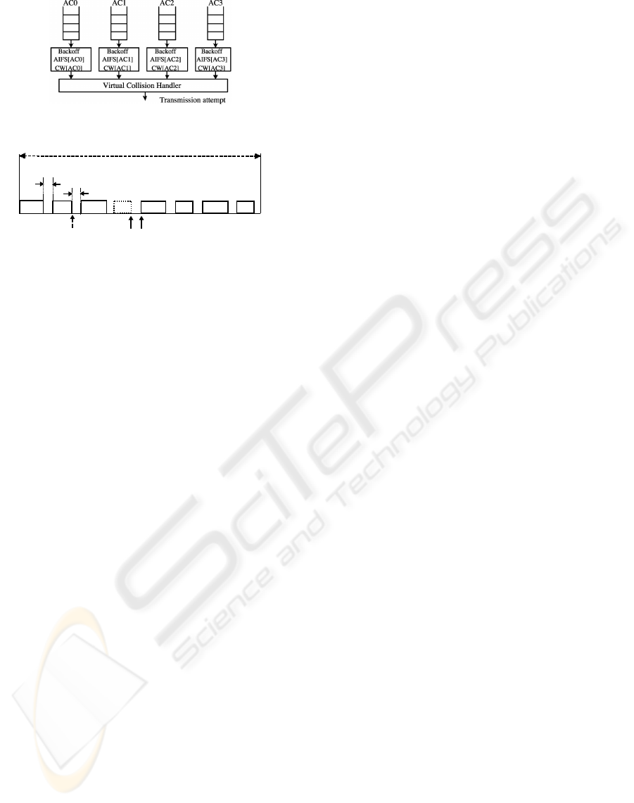
Figure 3: ACs queues and virtual collision.
Figure 4: RTS/CTS exchange, successful transmission, re-
transmission and collision time.
number of frames that can be successfully transmit-
ted during a TXOP is denoted by N
T XOP
. It is as-
sumed in this paper that Request-to-Send/Clear-to-
Send (RTS/CTS) scheme is used. Thus, before a
frame transmission, an RTS frame and a CTS frame
are exchanged between the communication pairs.
When the RTS/CTS frame processing is successfully
completed, the frame transmission will start. A suc-
cessful frame transmission is confirmed when the
sender successfully receives an immediate acknowl-
edgement (Imm-ACK) from the target receiver within
an expected period. Otherwise, the sender must re-
transmit the previous frame as long as the remaining
time in the TXOP is adequate for the new transmis-
sion. Figure 4 shows the transmission mechanisms.
The length of a TXOP is further restricted by the
start of the next BP (also the end of a superframe) or
the next DRP reservation. No PCA transmission may
delay or foreshorten BP or DRP reservation.
The DRP scheme provides a collision-free chan-
nel access. The scheme allows the stations to arbitrar-
ily reserve a number of MASs within the data trans-
mission period for exclusive communication. For
simplicity, it is assumed that only PCA scheme is im-
plemented, and the DRP scheme is not implemented.
3 THROUGHPUT ANALYSIS AND
FRAME LENGTH
OPTIMIZATION
The saturation throughput is a fundamental perfor-
mance indicator defined as the stable throughput limit
reached by the system as the offered load increases
(Bianchi, 2000). The analysis considers a fixed num-
ber of stations, denoted by M. Each of the station has
multiple ACs and every AC is assumed to always have
packets for transmission. A station will transmit as
many packets as it can including retransmissions dur-
ing its TXOP. The analysis ignores the signal propa-
gation delay because propagation delays are small (in
nano-second) in a short-range UWB network.
3.1 Analytical Model
To extend the model presented in (Kong et al., 2004)
for the WiMedia PCA scheme, new assumptions and
new transition probabilities will be introduced to the
three-dimensional Markov chain. Initially, as stated
in section 2, the limitation of a TXOP is further re-
stricted by the next BP. For simplicity, it is assumed
that any ongoing TXOP will be finished before the
end of a superframe, and that collision information
will be inferred to the transmitter before the end of
the current superframe. A collision is confirmed by
the transmitter if the expected ACK from the target re-
ceiver is not received within the expected period. The
duration of inferring this collision equals to that of a
successful transmission, as shown in Figure 4. The
probability that a station is activated within the PCA
period is calculated to statistically ensure that every
TXOP starts and ends within the PCA period. This
probability is denoted as P
PCA
, and given in (Wong
et al., 2007) as
P
PCA
= N
PCA
/N
SF
(4)
N
PCA
= N
SF
− N
BP
(5)
N
BP
= d(M + N
BSig+BExt
)T
BS
/T
MAS
e, M ≤ M
MAX
,
(6)
where N
PCA
, N
SF
, and N
BP
are the number of MASs
occupied by a PCA period, a superframe, and a BP,
respectively. The parameters T
BS
and T
MAS
are the
duration of a beacon slot and MAS duration in µs,
respectively. The parameter N
BSig+BExt
is the length
of the signaling and extension BS in total, and M
MAX
is the maximum number of stations allowed in a BP.
There is still probability that the next BP will arrive
between two adjacent TXOPs, or during the backoff
period.
The channel busy probability p
b
in the Markov
chain of (Kong et al., 2004) caused by the transmis-
sion of any station in a considered slot time is ex-
tended to p
b
+ P
BP
, since the WiMedia MAC also de-
fines the channel as busy during the BP. The previous
backoff process will resume subsequently.
The new stationary probability for an AC
i
to at-
tempt to access the channel within the PCA period in
a randomly chosen time slot is expressed as
τ
i
= [(1 − p
i
m+1
)/(1 − p
i
)]b
0,0,0
,
(7)
WINSYS 2008 - International Conference on Wireless Information Networks and Systems
116

where m is the maximum number of the backoff stage,
and b
0,0,0
is the probability for a station to be in the
original state. The expression of b
0,0,0
given in (Kong
et al., 2004) is extended as
b
0,0,0
= [
1 + N(p
b
+ P
BP
)
(p
b
+ P
BP
)
1 − (1 − (p
b
+ P
BP
))
A
i
+1
(1 − (p
b
+ P
BP
))
A
i
+1
+ dT
si
e(1 − p
i
m+1
) + (1 + dT
c
ep
i
)
1 − p
i
m+1
1 − p
i
+
1 + N(p
b
+ P
BP
)
2(1 − (p
b
+ P
BP
))
A
i
m
∑
j=0
W
j
p
i
j
]
−1
.
(8)
In (8), p
i
is the collision probabilities of the AC
i
,
and p
b
is the channel busy probability. The value of
W
j
is CW size depends on the backoff stage j and sat-
isfies W
j+1
= 2W
j
+ 1. In addition, the parameters T
si
and T
c
are the length of AC
i
’s TXOP and the collision
time which is the period elapsed before a station con-
firms a collision, respectively. A
i
is the duration of
each AC
i
’s AIFS.
Furthermore, the value of N in (8) is the expected
frozen time calculated using the value of the NAV
and the length of the BP. Since the value of the NAV
equals to the corresponding TXOP the expression of
N can be expressed as
N =
3
∑
i=0
p
si
T XOP
i
+ P
BP
N
BP
, (9)
where p
si
(16) is the probability that an AC
i
’s frame
can be transmitted successfully. Note that all the time-
related values are expressed with the same unit: back-
off slot σ.
The probability that a station attempts to access
the channel in any given time slot can be found us-
ing equation (7). It is equal to the probability that the
station has any type of AC’s data buffered for trans-
mission and is expressed as
τ = 1 −
3
∏
i=0
(1 − τ
i
) . (10)
Then, the collision probability of the AC
i
can be
written as
p
i
= 1 − (1 − τ)
M−1
∏
i
0
>i
(1 − τ
i
0
), (11)
where i
0
> i means that AC
0
i
has higher priority than
AC
i
. Equation (11) considers that a collision will oc-
cur if at least one of the other stations transmits or the
higher prioritized AC
i
in the station is transmitted at
the same time.
The probability that the channel is occupied by a
given AC
i
is the probability that the data is transmitted
or collide, and is given by
υ
i
= [dT
si
e(1 − p
i
m+1
) +dT
c
e
1 − p
i
m+1
1 − p
i
]b
0,0,0
. (12)
Thus, the probability that the channel is occupied
by a given station is
υ = 1 −
3
∏
i=0
(1 − υ
i
) . (13)
Furthermore, the probability that a channel is
busy, p
b
, which is also the probability that there is at
least one station transmitted or collide on the channel
can be expressed as
p
b
= 1 − (1 − υ)
M
. (14)
The successful access probability of the AC
i
within a time slot is the probability that the backoff
counter for this AC reaches zero at any backoff stage.
This probability is illustrated as
p
ti
= [dT
si
e(1 − p
i
m+1
)]b
0,0,0
. (15)
Finally, the probability that the AC
i
’s frame can be
transmitted successfully is the probability that there is
no other higher priority ACs in the same station and
only one station is transmitting. This probability is
given as
p
si
=
M p
ti
(1 − υ)
M−1
∏
i
0
>i
(1 − υ
i
0
)
1 − (1 − υ)
M
. (16)
Equations (7)–(16) form a set of nonlinear equa-
tions, which means that it can be solved by means of
numerical methods.
3.2 Throughput
The normalized system throughput, S
i
, is defined as
the fraction of time in which the channel is used
to successfully transmit the payload bits, and is ex-
pressed as
S
i
= [p
si
p
b
P
PCA
N
T XOP
(1 − p
e
)L/R]·
{[(1 − p
b
) + P
BP
]σ + p
si
p
b
P
PCA
T
si
+ p
b
P
PCA
(1 −
3
∑
j=0
p
s j
)T
c
}
−1
.
(17)
In (17), the factor p
si
p
b
P
PCA
N
T XOP
(1 − p
e
)L/R is
the mean amount of time needed for the payload in-
formation to be successfully transmitted in the PCA
period, and R is the fixed data rate.
Furthermore, the term [(1 − p
b
) + P
BP
]σ is the
expected number of the idle time slots due to ei-
ther non-transmission or BP’s occupation. The term
FRAME LENGTH DESIGN FOR MULTIBAND-OFDM ULTRA WIDEBAND NETWORKS
117

(1 −
∑
3
j=0
p
s j
)T
c
denotes the mean collision time for
the AC, and the value of the T
c
can be calculated using
T
c
= T
RT S
+ 2T
SIFS
+ T
CT S
Timeout
, (18)
where T
SIFS
is the duration of the Small Inter-frame
Space (SIFS), and T
RT S
is the time for the transmis-
sion of an RTS frame. T
RT S
is denoted as
T
RT S
= T
Preamble
+ T
Header
, (19)
where the value of T
Preamble
and T
Header
are the dura-
tion of the PLCP preamble and header, respectively.
In (18), the value of T
CT S
Timeout
equals to the suc-
cessful transmission time of a CTS which further
equals to the value of T
RT S
. The reason is that the size
of the RTS and the CTS frames are the same. Thus,
the value of T
c
equals to the duration for a successful
RTS/CTS frame exchange, denoted as T
s
.
The value of the N
T XOP
is calculated by
N
T XOP
i
= b
T
T XOP
i
− T
G
− T
s
T
PPDU
+ 2T
SIFS
+ T
ACK
c, (20)
where T
G
is the guard time, and T
PPDU
is the transmis-
sion time for the PLCP Protocol Data Unit (PPDU),
expressed as
T
PPDU
= T
Preamble
+ T
Header
+ T
SY M
N
Frame
. (21)
In (21), the value of T
SY M
is the OFDM symbol
interval, and N
Frame
is the number of OFDM symbols
of the PLCP payload. The calculation of these param-
eters is specified in the WiMedia standard.
Finally, by substituting (18)–(21) into (17), the
normalized throughput for an AC can be obtained.
3.3 Frame Length Optimization Design
The optimal frame length L in bits can be obtained
by solving the equation dS
i
/dL = 0 which can be ex-
pressed as
dS
i
dL
=
(1 − P
BER
)
L
+ L(1 − P
BER
)
L
log(1 − P
BER
)
G + HL
−
LH(1 − P
BER
)
L
(G + HL)
2
= 0 .
(22)
In (22), the parameter G is denoted as
G = A × D, (23)
where the factor A and D are expressed respectively
as
A = [(1 − p
b
) + P
BP
]σ + p
si
p
b
P
PCA
T
si
+
p
b
P
PCA
(1 −
3
∑
j=0
p
s j
)T
c
,
(24)
D = T
Preamble
+ T
Header
+ 2T
SIFS
+ T
ACK
+
6d(L
FCS
+ L
Tail
)T
SY M
/N
IBP6S
e .
(25)
Furthermore, the factor H in (22) is denoted as
H = A × E, (26)
where the term E is expressed as
E = 6dT
SY M
/N
IBP6S
e . (27)
Finally, the optimal length, L
opt
, can be calculated
from (22) as
L
opt
= {Glog(1 − P
BER
)+
[G
2
log
2
(1 − P
BER
)
2
− 4HGlog(1 − P
BER
)]
1/2
}·
[−2log(1 − P
BER
)H]
−1
.
(28)
It can be observed that the value of the optimal
frame length strongly depends on the value of the
BER which is decided by the value of the SNR. Equa-
tion (28) also shows that the value of the optimal
frame length is independent of the transmit data rate.
4 NUMERICAL RESULTS
The saturation throughput performance of the ACs
is initially investigated as a function of the frame
length. Subsequently, the variation of the optimal
frame length value against the value of the SNR is
analyzed. The used data rate is set to 200 Mbps, and
the number of the active stations is set to 10. It is
assumed that each station has all types of the ACs ac-
tivated (AC
0
to AC
3
). AC
3
has the highest priority.
The parameters used to obtain numerical results are
summarized in Table 1.
Both Figure 5 and Figure 6 illustrate that the satu-
ration throughput is sensitive to the frame length and
reaches the maximum at certain frame length value.
For example, when the SNR value is set to 24.0 dB
which corresponds to the BER value of 1.0e-3, the
saturation throughput of all the ACs reaches their cor-
responding maximum value when the frame length in-
creases to a value slightly more than 110 bytes. It can
be seen that the AC
2
has the highest maximum satura-
tion throughput value instead of the AC
3
. The reason
is that the AC
2
presents the longest TXOP duration
(1024 µs) which is much longer than that of the AC
3
(256 µs). The throughput value gradually decreases to
nearly zero when the frame length increases to more
than 500 bytes due to the large value of the PER.
It is also noticeable that the value of the optimal
frame length corresponding to the maximum satu-
ration throughput becomes larger when the SNR is
higher. For example, when the SNR is set to 14.0
WINSYS 2008 - International Conference on Wireless Information Networks and Systems
118
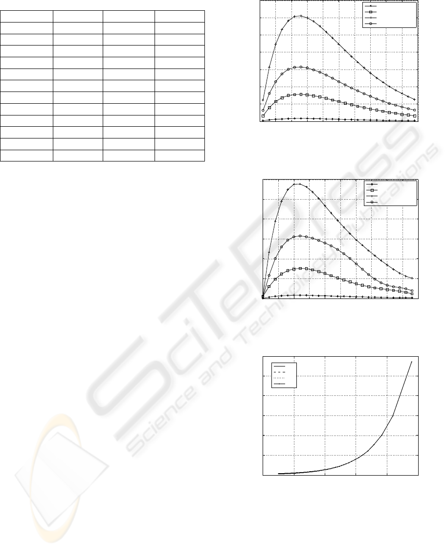
Table 1: Calculation and Simulation Parameters.
Parameter Value Parameter Value
M 10 N
IBP6S
375
T
Header
5.08µs T
Preamble
9.375µs
T
SY M
312.5ns T
G
12µs
T
SIFS
10µs σ 9µs
T
MAS
256µs T
BS
85µs
N
BSig+BExt
10 N
SF
256
AIFSN
AC
0
7 AIFSN
AC
1
4
AIFSN
AC
2
2 AIFSN
AC
3
1
TXOP
AC
0
512µs TXOP
AC
1
512µs
TXOP
AC
2
1024µs TXOP
AC
3
256µs
CW
AC
0
[15,1023] CW
AC
1
[15,1023]
CW
AC
2
[7,511] CW
AC
3
[3,255]
dB, the optimal frame length value of AC
2
is approx-
imately 12 bytes which is smaller than 110 bytes ob-
tained when the SNR is 24.0 dB. The reason is that
higher SNR values lead to lower BER values, and this
results in a lower PER value according to equations
(1) and (3).
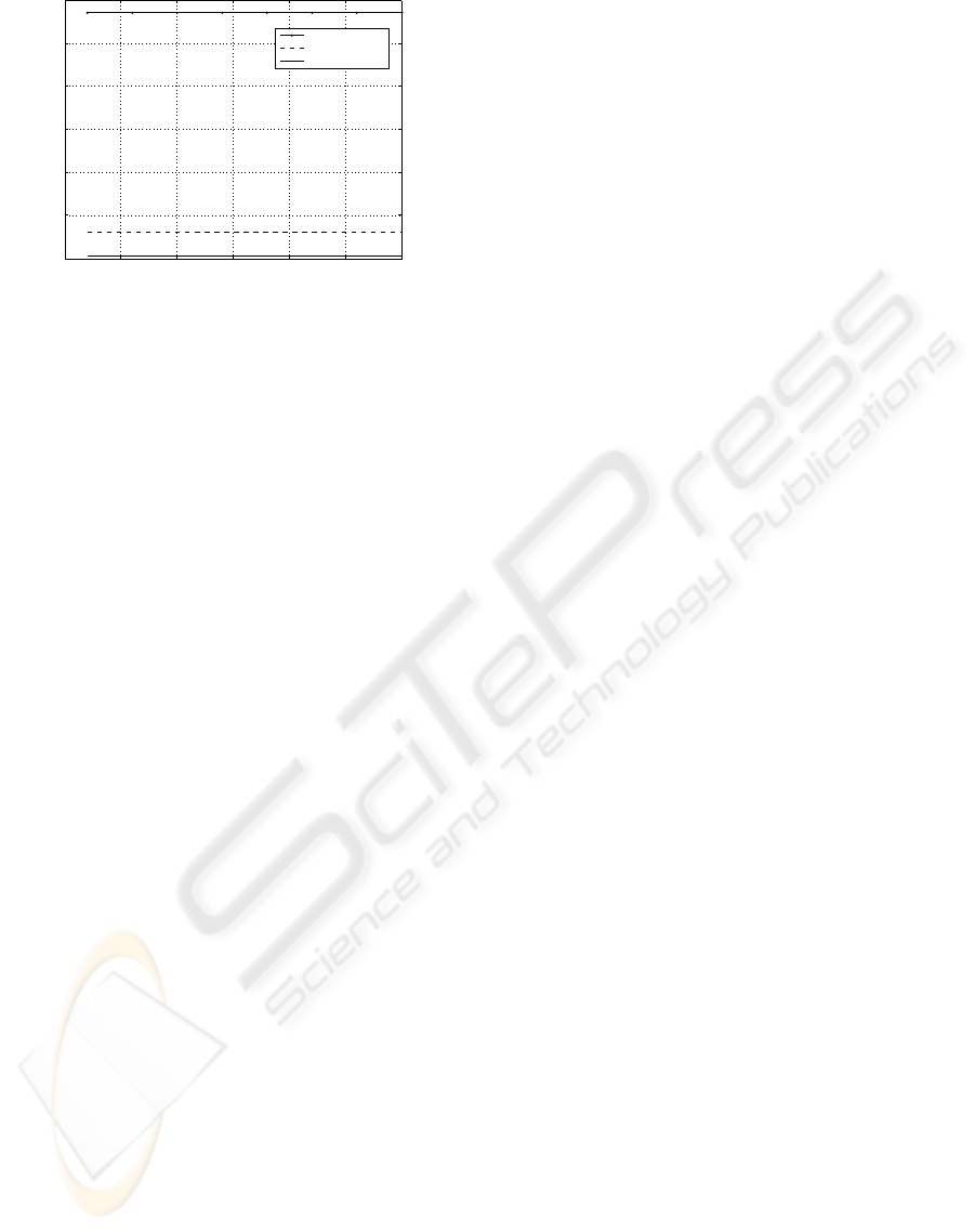
Furthermore, the results show that the optimal
frame length value is not affected by the change of
the priority of the AC. For instance, when the SNR
value is set to 14.0 dB, all of the ACs have almost the
same optimal frame length value of approximately 12
bytes. This observation is clearly illustrated in Fig-
ure 7. It can be seen that the values of the optimal
frame length of all the ACs increase exponentially as
the SNR value is higher. The variation profiles are al-
most the same for all of the ACs under different SNR
conditions.
Finally, Figure 8 illustrates the effect of the num-
ber of the active stations on the size of the optimal
frame length. It can be seen that the value of the opti-
mal frame length of AC
2
is always stable for any num-
ber of the active stations from two to thirty. Thus, it
means that the optimal value of the frame length can
be treated as independent of the number of the active
stations, the data rate, and the priority of the AC in the
WiMedia standard. Therefore, a station can dynami-
cally adapt the size of the transmitted frame length in
the MAC layer according to the current SNR level so
as to maximize its saturation throughput in the MB-
OFDM UWB network.
5 CONCLUSIONS
A new design of the optimal frame length for max-
imizing the saturation throughput of the WiMedia
PCA scheme over Rayleigh fading channel is pro-
posed. Initially, the analytical model of (Kong et al.,
0 5 10 15 20 25 30 35 40 45 50
0
0.5
1
1.5
2
2.5
3
3.5
x 10
−3
Length of the Payload
Saturation Throughput
AC0,SNR=14.0dB
AC1,SNR=14.0dB
AC2,SNR=14.0dB
AC3,SNR=14.0dB
Figure 5: Saturation throughput of the ACs against the
frame length (SNR=14.0dB).
0 50 100 150 200 250 300 350 400 450 500
0
0.005
0.01
0.015
0.02
0.025
0.03
Length of the Payload
Saturation Throughput
AC0,SNR=24.0dB
AC1,SNR=24.0dB
AC2,SNR=24.0dB
AC3,SNR=24.0dB
Figure 6: Saturation throughput of the ACs against the
frame length (SNR=24.0dB).
0 5 10 15 20 25
0
20
40
60
80
100
120
Average SNR (dB) per bit
Optimized Frame Length
AC0
AC1
AC2
AC3
Figure 7: The optimal frame length varies with respect to
the SNR.
2004) originally for EDCF scheme is extended into
the MB-OFDM UWB region for the throughput anal-
ysis. Subsequently, the proposed optimal frame
length design is carried out based on the extended
model. The new model inherits the advantages of the
original model and more importantly, the new model
takes into account the effect of TXOP limits and the
FRAME LENGTH DESIGN FOR MULTIBAND-OFDM ULTRA WIDEBAND NETWORKS
119
0 5 10 15 20 25 30
0
20
40
60
80
100
120
Number of the Active Stations
Optimized Frame Length
AC2,SNR=24.0dB
AC2,SNR=14.0dB
AC2,SNR=4.0dB
Figure 8: The optimal frame length varies with respect to
the number of active stations.
effect of the Rayleigh fading channel on the BER
value.
The results obtained in the simulation show that
the value of the throughput is sensitive to the frame
length and reaches the maximum at certain frame
length value. The optimal frame length increases ex-
ponentially when the value of SNR is higher and can
be treated as independent of the number of the active
stations, the data rate, and the priority of the AC in
the WiMedia standard. A station can then dynami-
cally adapt the transmitted frame length value in the
MAC layer according to the current value of the used
SNR so as to maximize its saturation throughput in
the MB-OFDM UWB network.
REFERENCES
Batra, A., Balakrishnan, J., and Dabak, A. (2003). “TI phys-
ical layer proposal for IEEE 802.15 task group 3a,”
IEEE P802.15-03/142r2-TG3a.
Bianchi, G. (2000). Performance analysis of the IEEE
802.11 distributed coordination function. IEEE J. Se-
lect. Areas. Commun., 18(3):535–547.
Deng, D.-J. and Chang, R.-S. (1999). A priority scheme
for IEEE 802.11 DCF access method. IEICE Trans.
Commun., E82-B(1):96–102.
ECMA International (2005). ECMA 368: High Rate Ultra
Wideband Phy and Mac Standard, Geneva: ECMA
International.
Federal Communications Commission (2002). “Revision of
part 15 of the commissions rules regarding ultra wide-
band transmission systems,” First Report and Order,
ET Docket 98-153, Washington, D.C.: Federal Com-
munications Commission.
IEEE Std. 802.11 (1999). Wireless LAN Medium Access
Control (MAC) and Physical Layer (PHY) Specifica-
tions, IEEE Std. 802.11, 1999 Edition.
IEEE Std. 802.11e (2003). Wireless medium access
control (MAC) and physical layer (PHY) specifica-
tions: Medium access control (MAC) enhancements
for quality of service (QoS), IEEE Std. 802.11e/Draft
5.0.
Kong, Z., Tsang, D. H. K., Bensaou, B., and Gao, D. (2004).
Performance analysis of IEEE 802.11e contention-
based channel access. IEEE J. Sel. Areas Commun.,
22(10):2095–2106.
Lai, H., Siriwongpairat, W., and Liu, K. (2007). Perfor-
mance analysis of multiband OFDM UWB systems
with imperfect synchronization and intersymbol inter-
ference. IEEE Journal of Selected Topics in Signal
Processing, 1(3):521–534.
Lu, K., Wu, D., Qian, Y., Fang, Y., and Qiu, R. C. (2007).
Performance of an Aggregation-Based MAC Protocol
for High-Data-Rate Ultrawideband Ad Hoc Networks.
IEEE Trans. on Vehicular Tech., 56(1):312–321.
Mangold, S., Choi, S., May, P., Klein, O., and Hiertz,
G. (2002). IEEE 802.11e wireless LAN for Quality
of Service, Proceedings European Wireless, Florence,
25-28 Feb., 2002, 32-39.
Taub, H. and Schilling, D. L. (1986). Principles of Commu-
nication Systems. McGraw-Hill, 2nd ed. New York p.
575-578.
Vishnevsky, V. M., Lyakhov, A. I., Safonov, A. A., Mo,
S. S., and Gelman, A. D. (2008). Study of Beaconing
in Multihop Wireless PAN with Distributed Control.
IEEE Trans. on Mobile Computing, 7(1):113–126.
WiMedia Alliance (2008). [Online], available:
www.wimedia.org/ [accessed 27 Mar. 2008].
Win, M. Z. and Scholtz, R. A. (1988). Impulse radio: How
it works. IEEE Communications Letters, 2(2):36–38.
Wong, D., Chin, F., Shajan, M., and Chew, Y. (2007). Sat-
urated Throughput of PCA with Hard DRPs in the
Presence of Bit Error for WiMedia MAC, Proceedings
Global Telecommunications Conference, Washington,
D.C., 26-30 Nov., 2007, 614-619.
Xiao, Y. (2005). Performance analysis of priority schemes
for IEEE 802.11 and IEEE 802.11e wireless LANs.
IEEE Trans. Commun., 4(4):1506–1515.
Zang, Y., Hiertz, G. R., Habetha, J., Otal, B., Sirin, H.,
and Reumerman, H.-J. (2005). Towards high speed
wireless personal area network - efficiency analysis of
MBOA MAC, Proceedings of the International Work-
shop on Wireless Ad-Hoc Networks, London, 23-26
May 2005, 10-20.
WINSYS 2008 - International Conference on Wireless Information Networks and Systems
120
