
MIMO-OFDM CHANNEL ESTIMATION
A Pilot Sequence Design for Time-domain Processing
Carlos Ribeiro
Instituto Politécnico de Leiria, Morro do Lena – Alto Vieiro, Leiria, Portugal
Atílio Gameiro
Instituto de Telecomunicações, Universidade de Aveiro, Aveiro, Portugal
Keywords: OFDM, MIMO, pilot-aided channel estimation, pilot sequence design, time-domain processing.
Abstract: A pilot sequence design for MIMO-OFDM systems is investigated where all transmit antennas share the
same sub-carriers to convey pilot symbols. The pilot sequences are endowed with phase-shifting properties,
granting the receiver the possibility of extracting the impulse responses for all channels directly from the
antennas’ time-domain received signals, without co-channel interference. A linear processing of the time-
domain samples is all that is needed to get the channel impulse responses, resulting in an algorithm with
very low computational load. The feasibility of the investigated method is substantiated by system
simulation using indoor and outdoor broadband wireless channel models.
1 INTRODUCTION
Future mobile broadband applications will require
reliable high data-rate wireless communication
systems. In recent years, multiple-input multiple-
output orthogonal frequency division multiplexing
(MIMO-OFDM) transmission systems (Nee, 2000),
(Stuber, 2004), (Sampath, 2005), (Paulraj, 2004),
emerged as the scheme with the potential to fulfill
these conditions, with bandwidth efficiency and
robustness to frequency selective channels, common
in mobile personal communication systems.
The accurate extraction of the channel state
information is crucial to realize the full potential of
the MIMO-OFDM system. The performance of the
channel estimator is vital for diversity combining,
coherent detection and decoding, and resource
allocation operations. The co-channel interference
inherent to the system, where the received signal is
the superposition of the signals transmitted
simultaneous from the different antennas, puts an
additional challenge on the design of the channel
estimation algorithm.
A decision-directed channel estimation scheme
that attempted to minimize the co-channel
interference was published in (Li, 1999). The
proposed algorithm exhibits a high computational
load. A simplified and enhanced algorithm,
introducing a data-aided scheme for the data
transmission mode, is presented in (Li, 2002). The
topic attracted a significant attention and has been
the focus of investigation in multiple publications
(Shin, 2004), (Zhang, 2005), (Zamiri-Jafarian, 2007)
and references therein.
The design of training symbols and pilot
sequences with the ability to decouple the co-
channel interference and minimize the channel
estimation mean square error (MSE) for MIMO-
OFDM was addressed in several publications (Li,
2002), (Barhumi, 2003) and (Minn, 2004).
Most publications on the topic of training-signal
or pilot-aided channel estimation use the frequency-
domain (FD) least squares (LS) estimates as the
starting point for the analysis of the estimation
algorithm or the design of the training sequence. It
was established in (Ribeiro, 2007) that in single-
input single-output (SISO) OFDM a time-domain
(TD) equivalent LS estimate could be obtained using
a simple linear operation on the received signal, if
the used pilot sequence fulfills certain conditions
(training sequences were treated as particular pilot
sequences with no data symbols in-between
consecutive pilot sub-carriers).
163
Ribeiro C. and Gameiro A. (2008).
MIMO-OFDM CHANNEL ESTIMATION - A Pilot Sequence Design for Time-domain Processing.
In Proceedings of the International Conference on Wireless Information Networks and Systems, pages 163-170
DOI: 10.5220/0002026101630170
Copyright
c
SciTePress

In this paper we develop a MIMO-OFDM pilot
sequence design and associated channel estimation
method that succeeds in extracting each channel
impulse response (CIR) estimate with minimal
computational load. The investigated scheme can be
used in either spatial multiplexing or space-time
coded systems, with all transmit antennas sharing
the same sub-carriers to convey its individual pilot
sequences, thus minimizing the system’s pilot
overhead. Using different phase-shifting pilot
sequences for each transmit antenna, together with
the result in (Ribeiro, 2007), the method succeeds in
separating the overlapping FD received pilots
sequences by using a TD algorithm that successfully
estimates the different CIRs and eliminates the co-
channel interference, under given conditions. The
STC algorithm (Li, 1999) or the TD LMMSE
criterion (Edfors, 1996) can be incorporated to
improve the estimate at little or no added
computational cost.
The paper is organized as follows. Next Section
gives a brief introduction to the wireless multipath
channel and the MIMO-OFDM baseband model. In
Section 3 the investigated pilot sequence design is
developed. The feasibility of the new method is
substantiated by simulation results presented in
Section 4. Finally, conclusions are drawn in Section
5.
2 MIMO-OFDM IN MOBILE
WIRELESS CHANNELS
Before introducing the investigated method, we will
briefly overview the mobile wireless multipath
channel and the considered MIMO-OFDM baseband
model.
Throughout the text, the notation
()
~
is used for
TD vectors and elements and its absence denotes FD
vectors and elements. The index n denotes TD
elements and k FD elements. Unless stated
otherwise, the vectors involved in the
transmission/reception process are column vectors
with
C
N complex elements. The superscripts
()
.
T
and
()
.
H
denote transpose and Hermitian transpose,
respectively.
2.1 The Wireless Multipath Channel
Let’s consider that the system transmits over
multipath Rayleigh fading wireless channels,
modeled by the discrete-time CIR,
Figure 1: MIMO-OFDM baseband system model.
[]
1
0
L
ll
l
hn n
α
δτ
−
=
=−
⎡⎤
⎣⎦
∑
, (1)
where L is the number of channel paths,
l
α
and
l
τ
are the complex value and delay of path l,
respectively. The paths are assumed to be
statistically independent, with normalized average
power,
1
2
0
1
L
l
l
σ
−
=
=
∑
, where
2
l
σ
is the average power
of path l. The channel is time-variant due to the
motion of the mobile terminal (MT), but we will
assume that the CIR is constant during one OFDM
symbol. The time dependence of the CIR is not
present in the notation for simplicity. Assuming that
the insertion of a long enough cyclic prefix (CP) in
the transmitter assures that the orthogonality of the
sub-carriers is maintained after transmission, the
channel frequency response (CFR) can be expressed
as,
[]
1
0
2
exp
L
l
l
C
hk j kl
N
π
α
−
=
⎡⎤
=−
⎢⎥
⎣⎦
∑
, (2)
where
C
N is the total number of sub-carriers of the
OFDM system.
2.2 MIMO-OFDM Baseband Model
Let’s consider the MIMO-OFDM baseband system
with
S
n transmit antennas and
R
n receive antennas
depicted in Figure 1. The system uses
C
N M-ary
PSK or QAM modulated sub-carriers. At time n, the
binary data vector b is coded into
S
n modulating
vectors
{
}
:1,,
s
S
s
n=d …
. The transmit antennas
simultaneously send
S
n OFDM signals modulated
by
s
d .
To assist in the channel estimation process, pilot
symbols are multiplexed together with data symbols.
OFDM
Mod
OFDM
Mod
Frame
Frame
1
p
S
N
p
1
d
S
N
d
OFDM
DeMod
OFDM
DeMod
De-
Frame
De-
Frame
1
s
S
N
s
S
N
s
1
s
1
y
R
N
y
1
r
R
N
r
Decision
ˆ
d
Channel
Estimation
WINSYS 2008 - International Conference on Wireless Information Networks and Systems
164

Each antenna path uses a different FD pilot vector
s
p . Vectors
s
d and
s
p contain non-zero values at
disjoint positions (sub-carriers). The resulting FD
signal transmitted by antenna s is
s
ss
s=d+p.
The OFDM modulator present on each antenna
path performs an
C
N -points inverse discrete Fourier
transform (IDFT) operation to transform the vector
s
s to TD. An L samples long guard interval, in the
form of CP, is prefixed to the resulting vector.
Antenna s TD transmitted vector
s
s
is,
()
H
s
CP s CP s s
s=A Fs=A d+p
, (3)
where
(
)
1, 1
2
,0,0
CC
C
NN
jkn
N
kn
e
π
−
−
−
=
F is the
CC
NN
×
discrete Fourier transform (DFT) matrix and
CC
T
CP N L N×
⎡⎤
=
⎣⎦
AII
is the matrix that adds the CP,
with
C
N
I denoting the
CC
NN
×
identity matrix and
C
NL×
I denoting the last L columns of
C
N
I . The TD
vectors
s
d
and
s
p
collect, respectively, the
components of data symbols and pilot symbols
present in
s
s
.
The transmission over uncorrelated wireless
channels results in a received signal vector
y
at
receive antenna r consisting of
S
n superimposed
transmitted signal samples,
11
,,
00
'' '
SS
nn
rrs rss
ss
−−
==
=+= +
∑∑
yywHsw
, (4)
where the vector
'w
is made-up of independent and
identically distributed (iid) zero mean additive white
Gaussian noise (AWGN) samples with variance
2
σ
w
. The vector
,,
'
rs rs s
=
y
Hs
represents the
contribution from transmit antenna s to the received
signal;
,
'
rs
H
is the
()()
CC
NLNL+× +
lower
triangular Toeplitz channel convolution matrix with
first column
,1
C
T
T
rs N×
⎡⎤
⎣⎦
h0
, where
,rs
h
is the column
L-vector with the discrete-time CIR from transmit
antenna s to receive antenna r and
1
C
N×
0
is a null
C
N -vector.
With the assumption that the signals in the
receive antennas are mutually uncorrelated, the
channel estimation at the receiver will be
independent for all channels and, in the following,
the receive antenna index will be dropped for
notation simplicity.
The OFDM demodulator in each receiving
antenna path starts by removing the CP from each
symbol. The resulting vector for symbols with pilots
and data is,
()
()
1
0
11
00
''
S
SS
n
CP CP s CP s s CP
s
nn
ss s s
ss
−
=
−−
==
== +
=+=+
∑
∑∑
rRy RHA d+p Rw
Hd+p w r w
, (5)
where
CC
CP N L N×
⎡
⎤
=
⎣
⎦
R0I
is the matrix that
removes the CP,
'
CP
=
wRw
is the TD noise vector,
(
)
s
ss s
=rHd+p
represents the contribution from
transmit antenna s to the received vector and
'
s
CP s CP
=HRHA
is the
CC
NN× circulant matrix
for channel s, with circulant vector
()
1
C
T
T
s
NL
×−
⎡⎤
⎣⎦
h0
.
The symbols are transformed back to FD with a
DFT operation. The resulting FD column
C
N -vector
can be expressed as,
()
1
0
S
n
ss s
s
−
=
=
=+
∑
rFr Hd+p w
, (6)
where
s
H is the
CC
NN
×
diagonal matrix whose
diagonal elements are defined by (2) and w is the FD
noise vector.
The deframing block in each receive antenna
path separates the signals in the sub-carriers
conveying pilots and data symbols. The signals in
the data sub-carriers are fed to the decision block.
3 A PILOT SEQUENCE DESIGN
FOR TD PROCESSING
The channel estimation algorithm must estimate the
SR
nn channels from the receive antennas’ signals.
The proposed method estimates the channels from
the symbols carrying pilots and data (the training
sequence is a particular case and the results can be
easily extended to it). All the processing required to
estimate the CIR is performed immediately on the
TD received vector
r
, eliminating the need to go
from TD to FD and back to TD to finally obtain the
CIR estimate (Li, 1999), (Li, 2002). The present
MIMO-OFDM CHANNEL ESTIMATION - A Pilot Sequence Design for Time-domain Processing
165

algorithm has a very low computational load and no
performance trade-offs. Under given conditions, the
co-channel interference is entirely eliminated. Data-
aided channel estimation algorithms (Li, 2002) can
be incorporated to further improve the algorithm’s
performance.
Consider the set of sub-carriers
℘
dedicated to
convey pilot symbols,
{}
0, , 2 , ,
ff Cf
NN NN℘= − , (7)
where the pilot distance
f
N can range from 1
(particular case where all sub-carriers in the OFDM
symbol are dedicated to transmit pilots – training
symbol) to
C
N , fulfilling the condition
C
t
f
N
N
N
=∈
. The set ℘ is common to all transmit
antennas (pilot sub-carriers overlap in receive
antennas).
The system uses distinct phase-shifted pilot
sequences in each transmit antenna. The k-th
element of the column
C
N -vector
s
p is defined by,
[]
1
0
2
exp
t
N
sf
m
S
s
jm
pk k mN
n
π
δ
−
=
⎡⎤
−
⎡⎤
=−
⎢⎥
⎣⎦
⎣⎦
∑
, (8)
giving rise to the corresponding TD vector
s
p
,
whose n-th element is,
[]
2
11
2
00
1
0
1
1
,
Ct
S
f
s
NN
jm
j
kn
n
Nc
sf
km
C
N
tt
m
fS S
pn k mN e e
N
sNt
nNmN
Nn n
π
π
δ
δ
−−
−
==
−
=
⎡⎤
=−
⎣⎦
⎡⎤
=−−∈
⎢⎥
⎣⎦
∑∑
∑
, (9)
or equivalently,
[] []
[]
[]
1
0
1
1
0
1
1
0
1
11
1
1
f
f
f
S
N
ot
m
f
N
tt
m
fS
N
S
ntt
m
fS
pn nmN
N
pn n N mN
Nn
n
pn n NmN
Nn
δ
δ
δ
−
=
−
=
−
−
=
⎧
=−
⎪
⎪
⎪
⎡⎤
⎪
=−−
⎪
⎢⎥
⎨
⎣⎦
⎪
⎪
⎪
⎡
⎤
−
⎪
=−−
⎢
⎥
⎪
⎣
⎦
⎩
∑
∑
∑
. (10)
Equation (10) shows that the transmit antennas’
pilot sequences do not overlap in TD, allowing the
separation of each transmit antenna’s CIR, as it will
be demonstrated.
The n-th element of
s
d
can be expressed by,
[] []
1
2
0
1
C
C
kn
N
j
N
ss
k
C
k
dn dke
N
π
−
=
∉℘
=
∑
, (11)
where
[
]
s
dk is the k-th element of
s
d (complex
data symbol conveyed by the k-th sub-carrier).
Replacing equation (9) in equation (5), the n-th
element of
r
is,
[] [] [] [] [ ]
[]
[] [ ]
[]
11
1
000
1
1
00
1
1
1
0
00 0
1
1
0
1
1
1
11
1
1
SS
f
S
f
S
f
S
nn
L
sss
ssl
N
n
stt
sm
fS
N
n
L
s
st
sl m
f
N
tt
m
fS
S
ntt
fS
rn rn wn hldnl
s
hn N mN wn
Nn
hldn l hn mN
N
hn N mN
Nn
n
hn NmN
Nn
−−
−
===
−
−
==
−
−
−
== =
−
=
−
=+= −
⎡⎤
+−−+
⎢⎥
⎣⎦
=−+−
⎡⎤
+−−+
⎢⎥
⎣⎦
⎡⎤
−
+−−
⎢⎥
⎣⎦
∑∑∑
∑∑
∑∑ ∑
∑
[]
1
0
f
N
m
wn
−
=
+
∑
. (12)
Equation (12) puts in evidence that antenna r
received signal is the sum of three distinct
components: the data vectors
s
d
and pilot vectors
s
p
, transmitted over its channels, and the AWGN.
Looking carefully at the component dependent on
the pilot vectors, it becomes clear that it is made-up
of
f
N scaled replicas of each of the
S
n CIR,
corresponding to the
S
n channels that link the
transmit antennas with the considered receive
antenna. Moreover, the replicas of each CIR are
separated by
t
N samples and transmit antenna s
CIR replicas are time-shifted
t
S
s
N
n
samples from
the reference position
{
}
, 0, , 1
tf
mN m N∈−
.
Figure 2 shows an example of a TD received
vector r
when 4
S
n
=
antennas transmit one
symbol carrying only pilots (data sub-carriers are not
loaded) over independent BRAN-A model multipath
channels (ETSI, 2001). The top plot represents the
overlapping of the signals from all transmit antennas
in one receive antenna. The four lower plots show
how the CIR replicas corresponding to each transmit
WINSYS 2008 - International Conference on Wireless Information Networks and Systems
166

antenna are phase-shifted and can be separated from
the overall signal. It gives a clear image of the
condition that each CIR must fulfill so that
consecutive replicas do not overlap.
Given the transmit antenna s maximum channel
delay spread,
s
τ
, and the system’s sampling
interval,
tΔ , the minimum pilot distance that can be
used without overlap of adjacent CIR replicas, thus
enabling the best performance of the channel
estimator, can be expressed as
C
f
Ss
Nt
N
n
τ
Δ
≤
. (13)
As it will be demonstrated, if the condition in
(13) is verified the co-channel interference will be
eliminated. Otherwise, the overlapping of
consecutive replicas will cause distortion in the
estimation process and impose an MSE floor on the
estimate.
Considering that the condition presented by (13)
is fulfilled, the transmit antenna s CIR estimate
vector
ˆ
s
h
can be obtained immediately from the TD
received vector
r
(Ribeiro, 2007),
[]
[]
[]
[]
1
0
1
0
11
00
, 0,1, , 1
ˆ
0,
1
1
f
f
ff
N
t
tt
m
s
SS
N
t
tt
m
SS
t
S
NN
stt
t
t
lm
fS
N
s
rn N mN n
hn
nn
remaining
N
s
un un r n N mN
nn
N
un un
n
hn mN lN
sN
wn mN
Nn
−
=
−
=
−−
==
⎧
⎡⎤
+− = −
⎪
⎢⎥
=
⎨
⎣⎦
⎪
⎩
⎛⎞
⎡⎤⎡ ⎤
=−−+ +−
⎜⎟
⎢⎥⎢ ⎥
⎜⎟
⎣⎦⎣ ⎦
⎝⎠
⎛⎞
⎡⎤
=−−+×
⎜⎟
⎢⎥
⎜⎟
⎣⎦
⎝⎠
−−
⎡⎤
++−
⎢⎥
⎣⎦
∑
∑
∑∑
[]
[]
1
1
00
1
1
1
000
1
0
1
, 0,1, , 1
0,
f
S
f
S
f
N
n
ms
N
n
L
ss t t
msl
fS
N
t
stt
m
SS
s
hld n N mN l
Nn
N
s
hn wn N mN n
nn
remaining
−
−
==
−
−
−
===
−
=
⎛⎞
⎜⎟
⎜⎟
⎜⎟
⎡⎤
⎜⎟
++−−
⎢⎥
⎜⎟
⎣⎦
⎝⎠
⎧
⎡⎤
++− = −
⎪
⎢⎥
=
⎨
⎣⎦
⎪
⎩
∑∑
∑∑∑
∑
,(14)
where
[
]
un
is the unit step function. The operation
in (14) estimates all
S
n CIR and must be repeated
for all
R
n receive antennas. The result in (14) is
possible because the data dependent component was
eliminated, considering that (Ribeiro, 2007),
[]
[] [ ]
1
1
1
000
11
1
00 0
1
0
1
12
exp
2
exp 0
f
S
SC
f
N
n
L
ss t t
msl
fS
nN
L
t
ss
sl k
Cf C S
k
N
t
m
C
s
hld n N mN l
Nn
sN
hl d k j kn l
NN N n
jkmN
N
π
π
−
−
−
===
−−
−
== =
∉℘
−
=
⎡⎤
+−−=
⎢⎥
⎣⎦
⎡⎤
⎛⎞
=+−
⎢⎥
⎜⎟
⎢⎥
⎝⎠
⎣⎦
⎡⎤
×− =
⎢⎥
⎣⎦
∑∑∑
∑∑ ∑
∑
(15)
Figure 2: Decomposition of the combined received symbol
(pilots only) for
4
S
n
=
transmit antennas.
The CIR estimate resulting of (14) is the TD LS
equivalent of a SISO OFDM system (Ribeiro, 2007).
Consider a constant envelope modulation (though it
can be easily extended for any modulation) with
transmit power equally distributed among the
S
n
antennas,
[]
{
}
2
1
s
S
Esk
n
=
. Pilot and data sub-
carriers are transmitted with equal power. Assuming
that the noise in the TD samples is iid, the noise
variance in (14) is
2
S
n
σ
w
, resulting in the channel
estimation MSE,
2
INI f
MSE N
σ
=
w
. (16)
This initial estimate can be improved by
incorporating other TD algorithms at little or no
added computational load. With the knowledge that
the CIR energy is concentrated in a small set of taps,
the significant tap catching (STC) scheme (Li, 1999)
lowers the channel estimation MSE considerably.
Further improvement is provided by the TD linear
MIMO-OFDM CHANNEL ESTIMATION - A Pilot Sequence Design for Time-domain Processing
167

minimum MSE (LMMSE) filter (Edfors, 1996), if
the channel correlation and noise variance are
known a-priori (due to the CIR energy
concentration, the estimation of these parameter is
quite simpler in TD, when compared to FD).
Considering the more realistic approach of non-
sample-spaced channel (where channel paths are not
separated by multiples of
tΔ and energy leakage
occurs), other algorithms (Edfors, 1996) can provide
further improvement with added computational load.
3.1 Including the STC Algorithm
The CIR energy of wireless multipath channels is
commonly limited to a small set of taps. By
identifying this set of significant taps and ignoring
the remaining, we are removing noise from the
channel estimate, thus improving it (Li, 2002).
Considering the channel model introduced in
Section 2, the CIR will only have L significant taps.
Assuming that the set of significant taps is
{
}
L
, (14)
can be rewritten
[]
{}
[]
{}
1
0
1
0
,
ˆ
0,
,
0,
f
f
N
tt
m
s
S
N
stt
m
S
s
rn N mN n L
hn
n
remaining
s
hn wn N mN n L
n
remaining
−
=
−
=
⎧
⎡⎤
+− ∈
⎪
⎢⎥
=
⎨
⎣⎦
⎪
⎩
⎧
⎡⎤
++−∈
⎪
⎢⎥
=
⎨
⎣⎦
⎪
⎩
∑
∑
.(17)
By eliminating the noise in the non-significant
taps, the noise variance in (17) is reduced to
2
f
C
LN
N
σ
w
and the resulting channel estimation MSE
is,
2
2
Sf Sf
STC INI
CC
nLN nLN
MSE MSE
NN
σ
==
w
. (18)
This MSE tends to the initial MSE when L goes
to
C
Sf
N
nN
(limiting condition in (13)). The channel
estimation MSE achieved in (Li, 2002) is the same
as in (18) when
1
f
N = (training sequence).
The use of the STC algorithm actually lowers the
computational load by limiting the summation
interval. An error floor will limit the performance
for high values of SNR if the set
{}
L
is not properly
estimated and some CIR energy is removed.
3.2 Including TD LMMSE Filter
For low values of SNR, a significant improvement in
the channel estimation can be achieved by using the
TD LMMSE filter that minimizes the effect of the
noise in the estimate.
Considering the channel model introduced in
Section 2, where all channel taps are separated by
multiples of
t
Δ
, the TD MMSE filter is
implemented by a diagonal matrix (Edfors, 1996)
whose diagonal elements are defined by
[
]
[]
2
hh
w
hh
f
Rn
Rn
N
σ
+
, where
hh
R
is the CIR correlation
matrix. Because all paths of all channels are
uncorrelated, the matrix will only have L non-zero
values in the diagonal elements defined by
{
}
L
.
Therefore, the operation can be implemented
simultaneously with the operation in (13),
[]
[
]
[]
{}
[] []
[]
{}
1
2
0
1
0
2
,
ˆ
0,
,
0,
f
f
N
hh
tt
m
s
S
w
hh
N
tt
s
hh
m
S
w
hh
Rn
s
rn N mN n L
hn
nRn
remaining
s
nNmN
Rnhn w
n
nL
Rn
remaining
σ
σ
−
=
−
=
⎧
⎡⎤
+− ∈
⎪
⎢⎥
=
+
⎨
⎣⎦
⎪
⎩
⎧
⎛⎞
⎡⎤
+−
+
⎪
⎜⎟
⎢⎥
⎜⎟
⎪
⎣⎦
⎝⎠
=
∈
⎨
+
⎪
⎪
⎩
∑
∑
. (19)
The resulting channel estimation MSE (Edfors,
1996) is,
[
]
[]
{}
2
2
2
2
Sf
hh
LMMSE
lL
C
Sf
hh
C
nN
Rl
MSE
N
nLN
Rl
N
σ
σ
∈
=
+
∑
w
w
. (20)
Observing (20), we can conclude that when
SNR →∞,
L
MMSE STC
M
SE MSE→ .
The use of LMMSE filter lowers the
computational load by limiting the summation
interval but requires additional calculations to
estimate the channel correlation and noise variance.
For non-sample-spaced channels, the CIR
correlation is no longer a diagonal matrix and this
estimator no longer guaranties the MMSE criterion.
However it still is the best trade-off between
performance and computational load (Edfors, 1996).
WINSYS 2008 - International Conference on Wireless Information Networks and Systems
168
0 5 10 15 20
10
-3
10
-2
10
-1
BER
Eb/N0 (dB)
Perfect CSI
TD LS
TD STC
TD MMSE
0 5 10 15 20
10
-3
10
-2
10
-1
BER
Eb/N0 (dB)
Perfect CSI
TD LS
TD STC
TD MMSE
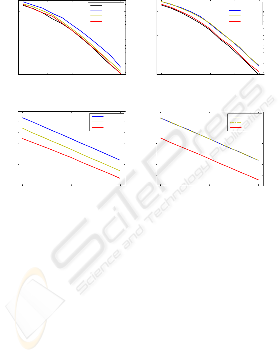
Figure 3: System BER performance (BRAN-A indoor
channel).
Figure 4: System BER performance (BRAN-E outdoor
channel).
0 5 10 15 20
-35
-30
-25
-20
-15
-10
-5
0
ChEst MSE (dB)
Eb/N0 (dB)
TD LS
TD STC
TD MMSE
0 5 10 15 20
-35
-30
-25
-20
-15
-10
-5
0
ChEst MSE (dB)
Eb/N0 (dB)
TD LS
TD STC
TD MMSE
Figure 5: Channel estimation MSE (BRAN-A indoor
channel).
Figure 6: Channel estimation MSE (BRAN-E outdoor
channel).
4 SIMULATION RESULTS
A simulation scenario was implemented using an
Alamouti
21× OFDM system with 1024Nc
=
QPSK modulated sub-carriers, sampling interval
10tnsΔ= and a CP with 200 samples. The
transmitted OFDM symbols carried pilots and data
using the proposed pilot structure, with a pilot
separation
4Nf = .
The BRAN-A and BRAN-E channel models [14]
were used to simulate indoor (
50ns rms delay
spread) and outdoor environments (
250ns rms delay
spread), respectively.
To validate the proposed method, BER and
channel estimation simulations were performed,
using Eb/N0 values in the range of 0dB to 20dB. The
3 channel estimation schemes presented in section 3
were simulated with both channel models.
The BER results are depicted in
Figure 3 and
Figure 4, respectively for BRAN-A and BRAN-E
channels.
The normalized channel estimation MSE results
are depicted in Figure 5 and Figure 6, respectively
for BRAN-A and BRAN-E channels.
On both scenarios, the TD LS and the TD
MMSE methods present a consistent performance.
The TD LS method always achieves the worst
performance (
2dB
≈
degradation in the BER
compared with the perfect channel state information
– CSI) due to the fact that it does not take advantage
of the channel characteristics. In opposition, the TD
MMSE method always achieves the best
performance, near the ideal situation. It has the
ability of dealing with the increasing channel delay
spread by always weighing the energy of channel
taps vs. noise variance.
The performance of the TD STC method (Li,
2002) is closely dependent on the channel delay
spread. Its performance is bond by the 2 previous
methods. A channel with a short delay spread will
result in the best performance (by having the CIR
energy concentrated to just a few taps, most of the
noise is eliminated in the estimation process). As the
MIMO-OFDM CHANNEL ESTIMATION - A Pilot Sequence Design for Time-domain Processing
169

channel delay spread increases, the performance
tends to that of the TD LS method, with a significant
performance degradation.
5 CONCLUSIONS
We have presented a pilot sequence design and
associated channel estimation algorithms for MIMO-
OFDM systems, where all transmit antennas share
the same sub-carriers to convey pilot symbols. The
proposed design grants the receiver the ability of
extracting the CIRs by processing the antennas’ TD
received samples, without co-channel interference,
resulting in an algorithm with very low
computational load.
The investigated method presents a considerable
performance improvement when compared to the
method in (Li, 2002), especially in the more
demanding outdoor environments, where it shows
the ability of maintaining the performance despite
the increased channel delay spread.
ACKNOWLEDGEMENTS
The authors wish to thank Fundação para a Ciência e
a Tecnologia that partially supported this work
through the project “PHOTON - Distributed and
Extendible Heterogeneous Radio Architectures
using Fibre Optic Networks” (PTDC/EEA-
TEL/72890/2006).
REFERENCES
Nee, R. V., Prasad, R., 2000. OFDM for Wireless
Multimedia Communications, Artech House. 1
st
edition.
Stuber, G. L., Barry, J. R., McLaughlin, S. W., Li, Y.,
Ingram, M. A., Pratt, T. G., 2004. Broadband MIMO-
OFDM wireless communications. In Proceedings of
the IEEE, vol. 92, no. 2, pp. 271–294.
Sampath, H., Talwar, S., Tellado, J., Erceg, V., Paulraj,
A., 2005. A fourth-generation MIMO-OFDM
broadband wireless system design, performance, and
field trial results. In IEEE Communications Magazine,
pp. 143–149.
Paulraj, A. J., Gore, D. A., Nabar, R. U., Bolcskei, H.,
2004. An overview of MIMO communications - a key
to gigabit wireless. In Proceedings of the IEEE, vol.
92, no. 2, pp. 198–218.
Li, Y. G., Seshadri, N., Ariyavisitakul, S., 1999. Channel
estimation for OFDM systems with transmitter
diversity in mobile wireless channels. In IEEE Journal
on Selected Areas in Communications, vol. 17, no. 3,
pp. 461–471.
Li, Y. G., 2002. Simplified channel estimation for OFDM
systems with multiple transmit antennas. In IEEE
Transactions on Wireless Communications, vol. 1, pp.
67–75.
Shin, M., Lee, H., Lee, C., 2004. Enhanced channel-
estimation technique for MIMO-OFDM systems. In
IEEE Transactions on Vehicular Technology, vol. 53,
no. 1, pp. 261–265.
Zhang, H., Li, Y. G., Reid, A., Terry, J., 2005. Channel
estimation for MIMO-OFDM in correlated fading
channels. In IEEE International Conference on
Communications, pp. 2626-2630.
Zamiri-Jafarian, H., Pasupathy, S., 2007. Robust and
improved channel estimation algorithm for MIMO-
OFDM systems. In IEEE Transactions on Wireless
Communications, vol. 6, pp. 2106-2113.
Barhumi, I., Leus, G., Moonen, M., 2003. Optimal training
design for MIMO OFDM systems in mobile wireless
channels. In IEEE Transactions on Signal Processing,
vol. 51, pp. 1615-1624.
Minn, H., Al-Dhahir, N., 2004. Optimal training signals
for MIMO OFDM channel estimation. In IEEE Global
Telecommunications Conference, pp. 219-224.
Ribeiro, C., Gameiro, A., 2007. Direct time-domain
channel impulse response estimation for OFDM-based
systems. In IEEE Vehicular Technology Conference.
Edfors, O., 1996. Low-complexity algorithms in digital
receivers, Ph.D. dissertation, Lulea University of
Technology, Sweden.
ETSI TS 101 475 V1.2.2, 2001. Broadband Radio Access
Networks (BRAN): HIPERLAN Type 2: Technical
specification; Physical layer.
WINSYS 2008 - International Conference on Wireless Information Networks and Systems
170
