
SELF-ORGANIZING DSP CIRCUITS
Andr´e Stauffer and Jo¨el Rossier
Logic Systems Laboratory, Ecole polytechnique f´ed´erale (EPFL), CH-1015 Lausanne, Switzerland
Keywords:
Bio-inspiration, Configuration, Cloning, Cicatrization, Regeneration.
Abstract:
Living organisms are endowed with three structural principles: multicellular architecture, cellular division,
and cellular differentiation. Implemented in digital according to these principles, our DSP circuits present
self-organizing mechanisms like configuration, cloning, cicatrization, and regeneration. These mechanisms
are made of simple processes such as growth, load, branching, repair, reset, and kill. The description of a con-
figurable molecule implementing the self-organizing mechanisms and its application to a multiplier function
constitute the core of this paper.
1 INTRODUCTION
Borrowing the structural principles from living organ-
isms, we have already shown how to grow cellular
systems thanks to an algorithm for cellular division
(Mange et al., 2004). These cellular systems are en-
dowed with self-organizing properties like configura-
tion, cloning, cicatrization, and regeneration (Stauffer
et al., 2005).
In a previous work (Stauffer et al., 2006), the
configuration mechanisms (structural and functional
growth), the cloning mechanisms (cellular and organ-
ismic self-replication), the cicatrization mechanism
(cellular self-repair), and the regeneration mechanism
(organismic self-repair) were already devised as the
result of simple processes like growth, load, branch-
ing, repair, reset, and kill. The goal of this paper is to
implement these mechanisms in DSP circuits.
Starting with the cellular architecture of the DSP
circuits, Section 2 will point out how the bio-inspired
properties like cloning, cicatrization, and regenera-
tion apply to these kind of circuits. Section 3 intro-
duces digital simulations to describe the data and the
signals involved in the corresponding self-organizing
mechanisms and their underlying processes. We de-
fine then the detailed molecular architecture of the cir-
cuits (Section 4) and devise a multiplier as an appli-
cation example (Section 5). A brief conclusion (Sec-
tion 6) summarizes our paper and opens new research
avenues.
2 BIO-INSPIRED PROPERTIES
2.1 Cellular Architecture
DSP circuits are made up of identical slices. They can
be seen as multicellular organisms made up of identi-
cal cells. Each slice processes one data bit and corre-
sponds to a cell made up of functionally configurable
molecules. The minimal cell consists of two rows of
three molecules with two columns of application spe-
cific molecules to the left and one column of spare
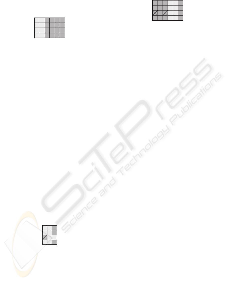
molecules (SM) to the right (Fig. 1).
SM
Figure 1: DSP slice corresponding to a minimal cell made
up of six molecules.
The minimal multicellular organism is made up of
two identical cells and represents a DSP circuit pro-
cessing two data bits (Fig. 2).
SM
Figure 2: DSP circuit corresponding to a minimal organism
made up of two cells.
The minimal population of organisms is made up
of two identical organisms. The left one consists of
197
Stauffer A. and Rossier J. (2009).
SELF-ORGANIZING DSP CIRCUITS.
In Proceedings of the International Conference on Bio-inspired Systems and Signal Processing, pages 197-203
DOI: 10.5220/0001120401970203
Copyright
c
SciTePress
two specific application cells while the right one is
composed of two spare cells (SC, Fig. 3).
SC
Figure 3: DSP circuit corresponding to a minimal popula-
tion of organisms made up of two organisms.
2.2 Cloning
The cloning or self-replication can be implemented
at the cellular level in order to build a multicellular
organism and at the organismic level in order to gen-
erate a population of organisms. The cloning of the
minimal cell displayed in Fig. 1 results thus in the or-
ganism of Fig. 2. The cloning of this organism defines
the population of Fig. 3.
2.3 Cicatrization
The introduction in the cells of the minimal organ-
ism of one column of spare molecules (SM, Fig. 2),
defined by a specific structural configuration, and the
automatic detection of faulty molecules (by a built-in
self-test mechanism which constantly compares two
copies of the same molecule) allows cicatrization or
self-repair at the cellular level: each faulty molecule is
deactivated, isolated from the network, and replaced
by the nearest right molecule, which will itself be re-
placed by the nearest right molecule, and so on until
a spare molecule (SM) is reached (Fig. 4). The num-
ber of faulty molecules handled by the cicatrization
mechanism is necessarily limited: in the example of
Fig. 2, we tolerate at most one faulty molecule per
row.
SM
Figure 4: Cicatrization of the minimal organism.
2.4 Regeneration
In order to implement regeneration, that is self-repair
at the organismic level, we need at least one spare or-
ganism to the right of the original organism (Fig. 3).
The existence of two faulty molecules in a same row
identifies the faulty organism which is deactivated
(Fig. 5). The functionality of the DSP circuit is now
SC
Figure 5: Regeneration of the minimal organism.
performed by the spare cells (SC) of the organism to
the right.
3 SELF-ORGANIZING
MECHANISMS
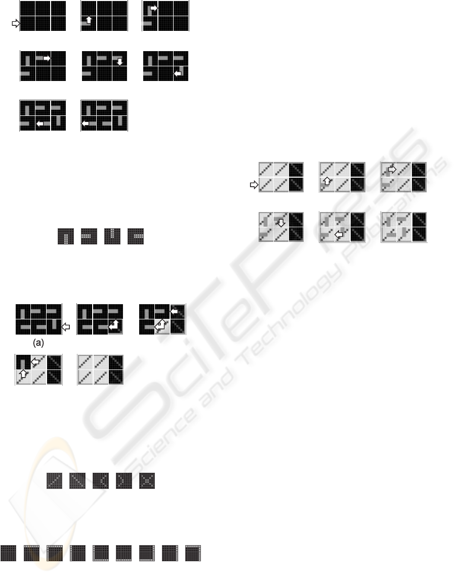
3.1 Structural Configuration
The goal of the structural configuration mechanism is
to define the boundaries of the cell as well as the liv-
ing mode or spare mode of its constituting molecules.
This mechanism is made up of a structural growth
process followed by a load process.
The growth process starts when an external growth
signal is applied to the lower left molecule of the cell
(Fig. 6a) and this molecule selects the corresponding
eastward data input (Fig. 6b). According to the struc-
tural configuration data or structural genome, each
molecule of the cell generates then successively an
internal growth signal and selects an input (Fig. 7),
in order to create a data path among the molecules of
the cell (Fig. 6b-g). When the connection path be-
tween the molecules closes, the lower left molecule
delivers a close signal to the nearest left neighbor cell
(Fig. 6h). The structural configuration data is now
moving around the data path and ready to be trans-
mitted to neighboring cells.
The load process is triggered by the close sig-
nal applied to the lower right molecule of the cell
(Fig. 8a). A load signal propagates then westward
and northward through the cell (Fig. 8b-d) and each of
its molecules acquire a molecular mode (Fig. 9) and a
molecular type (Fig. 10). We finally obtain an homo-
geneous tissue of molecules defining both the bound-
aries of the cell and the position of its living mode and
spare mode molecules (Fig. 8e). This tissue is ready
for being configured by the functional configuration
data.
3.2 Functional Configuration
The goal of the functional configuration mechanism
is to store in the homogeneous tissue, which already
contains structural data (Fig. 8e), the functional data
BIOSIGNALS 2009 - International Conference on Bio-inspired Systems and Signal Processing
198
(e)
(f)
(g)
(a)
(b) (c)
(d)
(h)
Figure 6: Structural growth process of the minimal cell
made up of six molecules. (a) External growth signal ap-
plied to the lower left molecule. (b-g) Generation of internal
growth signals to build the structural data path. (h) Closed
path and close signal delivered to the nearest left neighbor
cell.
(a) (b) (c) (d)
Figure 7: Data input selection. (a) Northward. (b) East-
ward. (c) Southward. (d) Westward.
(b)
(c)
(d)
(e)
Figure 8: Load process. (a) External close signal applied
to the lower right molecule by the nearest right neighbor
cell. (b-e) Generation of internal load signals propagating
westward and northward to store the molecular modes and
types of the cell.
(a) (b) (c) (d)
(e)
Figure 9: Molecular modes. (a) Living. (b) Spare. (c)
Faulty. (d) Repair. (e) Dead.
(b) (c) (d)
(a)
(e) (f)
(g) (h)
(i)
Figure 10: Molecular types. (a) Internal. (b) Top. (c) Top-
left. (d) Left. (e) Bottom-left. (f) Bottom. (g) Bottom-right.
(h) Right. (i) Top-right.
needed by the specifications of the current applica-
tion. This mechanism is a functional growth process,
performed only on the molecules in the living mode
while the molecules in the spare mode are simply by-
passed. It starts with an external growth signal ap-
plied to the lower left living molecule (Fig. 11a). Ac-
cording to the functional configuration data or func-
tional genome, the living molecules then successively
generate an internal growth signal, select an input,
and create a path among the living molecules of the
cell (Fig. 11b-f). The functional configuration data
is now moving around the data path and ready to be
transmitted to neighboring cells.
(a)
(b) (c)
(d)
(e)
(f)
Figure 11: Functional configuration of the cell per-
formed as a functional growth process applied to the living
molecules. (a) External growth signal applied to the lower
left molecule. (b-e) Generation of internal growth signals in
order to build the functional data path. (f) Closed functional
data path.
3.3 Cloning
The cloning mechanism or self-replication mecha-
nism is implemented at the cellular level in order to
build a multicellular organism and at the organismic
level in order to generate a population of organisms.
This mechanism suppose that there exists a sufficient
number of molecules in the array to contain at least
one copy of the additional cell or of the additional or-
ganism. It corresponds to a branching process which
takes place when the structural and the functionalcon-
figuration mechanisms deliver northward and east-
ward growth signals on the borders of the cell during
the corresponding growth processes (Fig. 12).
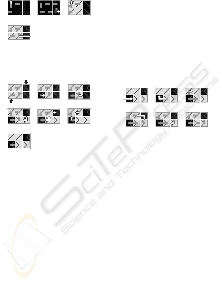
3.4 Cicatrization
Fig. 11f, shows the normal behavior of a healthy min-
imal cell, i.e. a cell without any faulty molecule. A
molecule is considered as faulty, or in the faulty mode,
if some built-in self-test detects a lethal malfunction.
Starting with the normal behavior of Fig. 11f, we sup-
pose that two molecules will become suddenly faulty
(Fig. 13a): (1) The lower left molecule, which is in the
living mode. (2) The upper right molecule, which is in
SELF-ORGANIZING DSP CIRCUITS
199
(a)
(b) (c)
(d)
Figure 12: Generation of growth signals triggering the
cloning mechanism. (a) Northward structural branching
process. (b) Eastward structural branching process. (c)
Northward functional branching process. (d) Eastward
functional branching process.
(a)
(b) (c)
(d)
(e)
(f)
(g)
Figure 13: Cicatrization mechanism performed as a repair
process followed by a reset process. (a) Living and spare
molecules becoming faulty. (b-c) Generation of repair sig-
nals propagating eastward. (d-f) Generation of internal re-
set signals propagating westward and northward. (g) Cell,
comprising two faulty and two repair molecules, ready for
functional reconfiguration.
the spare mode. While there is no change for the up-
per right molecule, which is just no more able to play
the role of a spare molecule, the lower left one trig-
gers a cicatrization mechanism. This mechanism is
made up of a repair process involving eastward prop-
agating repair signals (Fig. 13b-c) followed by a re-
set process performed with westward and northward
propagating internal reset signals (Fig. 13d-g). This
tissue, comprising now two molecules in the faulty
mode and two molecules in the repair mode, is ready
for being reconfigured by the functional configuration
data. This implies a functional growth process by-
passing the faulty molecules (Fig. 14).
3.5 Regeneration
Our minimal cell comprises a single spare molecule
per row and tolerates therefore only one faulty
molecule in each row. A second faulty molecule in
the same row will cause the death of the whole cell,
and the start of a regeneration mechanism. Fig. 15 il-
lustrates the repair process and kill process involved
in this mechanism. Starting with the normal behavior
of the cicatrized cell (Fig. 14f), a new molecule, the
upper middle one, becomes faulty. In a first step, the
new faulty molecule sends a repair signal eastward,
in order to look for a spare molecule, able to replace
it (Fig. 15b). In a second step, the supposed spare
molecule, which is in fact a faulty one, enters the
lethal dead mode and triggers kill signals which prop-
agate northward, westward and southward (Fig. 15c-
f). Finally in Fig. 15g, all the molecules of the array
are dead as well as our minimal system.
(a)
(b)
(c)
(d)
(e)
(f)
Figure 14: Functional reconfiguration of the living and re-
pair molecules. (a) External growth signal bypassing the
lower left faulty molecule. (b-e) Generation of internal
growth signals to build a functional data path bypassing the
faulty molecules. (f) Closed functional data path within the
living and repair molecules.
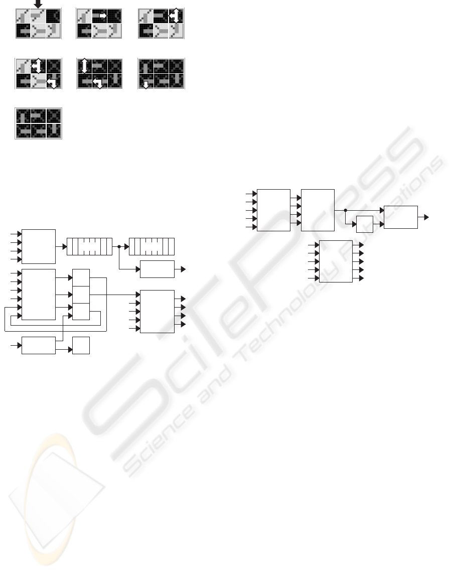
4 CONFIGURABLE MOLECULE
4.1 Control Layer
We will now describe the detailed architecture of the
control layer of our basic configurable molecule. This
layer, which implements the self-organizing mecha-
nisms and their constituting processes, corresponds
to a data and signals cellular automaton (DSCA) cell
(Stauffer and Sipper, 2004). It results from the inter-
connection of the following resources (Fig. 16):
• An input multiplexer DIMUX, selecting one out
of the four configuration input data NDI, EDI,
SDI or WDI.
• A 2N-level stack organized as N genotypic regis-
ters G1 to GN (for mobile configuration data), and
N phenotypic registers P1 to PN (for fixed config-
uration data).
• An output buffer DOBUF producing the configu-
ration output data DO.
• An encoder ENC for the input signals NSI, ESI,
SSI, and WSI.
BIOSIGNALS 2009 - International Conference on Bio-inspired Systems and Signal Processing
200
(a)
(b) (c)
(d)
(e)
(f)
(g)
Figure 15: Regeneration mechanism performed as a repair
process followed by a kill process. (a) Living molecule be-
coming faulty. (b) Eastward repair signal. (c-f) Genera-
tion of internal and external kill signals propagating north-
ward, westward and southward. (g) Cell made up six dead
molecules.
DIMUX
NDI
WDI
SDI
EDI
G1:N P1:N
DOBUF
DO
I
ENC
WSI
SSI
ESI
NSI
GEN
PN
PN-1
GN-1
WSO
SSO
ESO
NSO
S
M
DEC TPN-1
WSI
Figure 16: Detailed architecture of the control layer of the
molecule.
• A decoder DEC defining the mode and the type of
the molecule.
• A transmission register I for the memorization of
the input selection.
• A signal register S.
• A mode register M.
• A type register T.
• A generator GEN producing the output signals
NSO, ESO, SSO, and WSO.
4.2 Processing Layer
The processing layer implements the logic design of
the DSP application under development as well as its
routing connections between neighboring and distant
molecules. This layer, which is configured by the
fixed data of the phenotypic registers P1 to PN-1, is
made up of the following resources (Fig. 17):
• An input multiplexer AIMUX, selecting four in-
puts out of the four application data NAI, EAI,
SAI, WAI, and the routing data RO.
• A 16-bit look-up table LUT.
• A D-type flip-flop DFF for the realization of se-
quential circuits.
• An output multiplexer AOMUX selecting the
combinational or the sequential data as applica-
tion output AO.
• An output multiplexer ROMUX selecting the five
outputs NRO, ERO, SRO, WRO, and RO out of
the four routing input data NRI, ERI, SRI, WRI,
and the application output data AO.
AOMUX
AO
WAI
SAI
EAI
NAI
RO
LUT
DFF
AIMUX
ROMUX
ERI
AO
WRI
SRI
NRI
NRO
ERO
SRO
WRO
RO
Figure 17: Detailed architecture of the processing layer of
the molecule.
5 MULTIPLIER APPLICATION
5.1 Basic Cell
Even if the final goal is the self-organization of DSP
circuits, we will use a simplified application exam-
ple, the multiplication function (Andrejas and Trost,
2000), in order to illustrate its basic mechanisms. The
circuit that multiplies two 4-bit signals X andY can be
considered as a one-dimensional artificial organism
composed of four identical cells. Each cell is made
up of ten application specific molecules (Fig. 18):
• Four C molecules computing the carry output of a
1-bit adder.
• Four S molecules computing the sum output of a
1-bit adder.
• One D molecule generating a deactivation signal
in order to bypass the cells of the neighboring
spare organism to the right.
• One R molecule recovering the multiplication re-
sult performed by the living organism.
SELF-ORGANIZING DSP CIRCUITS
201
C
S
C
S
C
S
C
S
D
R
Xi
Y0 Y1 Y2 Y3
Ri
Figure 18: Basic cell of the 4-bit signals X and Y multiplier.
5.2 Structural Configuration,
Functional Configuration and
Cloning
In order to build the multicellular organism of Fig. 19,
the structural configuration mechanism, the func-
tional configuration mechanism, and the cloning
mechanism are applied at the cellular level. Start-
ing with the structural and functional configuration
data of the basic cell, these mechanisms generate
successively the four identical cells of the multiplier
organism. In this implementation, each individual
cell of the organism presents two columns of spare
molecules.
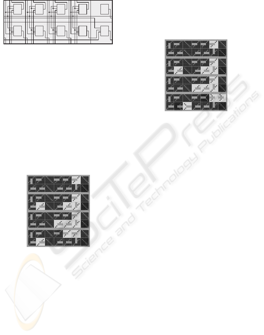
Figure 19: One-dimensional organism composed of four
cells resulting from the structural configuration, functional
configuration and cloning mechanisms applied to the basic
cell.
5.3 Cicatrization and Functional
Reconfiguration
The cicatrization mechanism (or cellular self-repair)
results from the introduction of the columns of spare
molecules (Fig. 19), defined by the structural configu-
ration of the basic cell, and the automatic detection of
faulty molecules. Thanks to this mechanism, each of
the two faulty molecules of the lower cell (Fig. 20) is
deactivated, isolated from the network, and replaced
by the nearest right molecule, which will itself be re-
placed by the nearest right molecule, and so on until a
spare molecule is reached. The functional reconfigu-
ration mechanism takes then place in order to regener-
ate the multiplier organism. As shown in Fig. 20, the
regenerated organism presents some graphical distor-
tion.
Figure 20: Graphical distortion resulting from the cicatriza-
tion and reconfiguration mechanisms applied to the lower
cell of the organism.
5.4 Regeneration
Each individual cell of the multiplier having two spare
columns (Fig. 19), this implementation allows at most
two faulty molecules per row. When a third one is
detected, the regeneration mechanism (or organismic
self-repair) takes place and all the cells of the organ-
ism are considered faulty and are deactivated. The
functions of the faulty cells are thus shifted to the
spare cells to the right. Obviously, this process re-
quires at least one spare organism to the right. As
shown in Fig. 21, the repair of the faulty organism
needs the spare organism to the right and leaves a scar
in the implementation.
6 CONCLUSIONS
The self-organizing mechanisms are made of simple
processes like growth, load, branching, repair, re-
set, and kill. They allow the DSP circuits to pos-
sess three bio-inspired properties: (1) Cloning or self-
replication at cellular and organismic levels. (2) Ci-
catrization or self-repair at the cellular level. (3) Re-
generation or self-repair at the organismic level.
Starting with a minimal DSP slice, a cell made of
six molecules, we realized digital simulations in order
to describe the data and signals involved in the self-
organizing mechanisms. These mechanisms are im-
plemented in the control layer of a basic configurable
molecule. The processing layer of the molecule im-
plements the logic design of the DSP circuit under de-
velopment. A 4-bit multiplier, an organism made of
BIOSIGNALS 2009 - International Conference on Bio-inspired Systems and Signal Processing
202

Figure 21: Scar resulting from the regeneration mechanism
applied to the organism.
four cells, was introduced as an application example
for the simulation of our mechanisms and their under-
lying processes.
The configurable molecule presented here will be
implemented in the ubichip (Upegui et al., 2007), a
programmable circuit that draws inspiration from the
multi-cellular structure of complex biological organ-
isms. The processing layer of the ubichip molecule is
a conventionalprogrammable block. In order to allow
the configuration of complex DSP circuits, this layer
must include some more specific DSP features.
REFERENCES
Andrejas, J. and Trost, A. (2000). Reusable DSP func-
tions in FPGAs. In Hartenstein, R. and Gr¨unbacher,
H., editors, Field-Programmable Logic and Appli-
cations: The Roadmap to Reconfigurable Comput-
ing (FPL 2000), Lecture Notes in Computer Science.
Springer-Verlag, Heidelberg.
Mange, D., Stauffer, A., Petraglio, E., and Tempesti, G.
(2004). Self-replicating loop with universal construc-
tion. Physica D, 191(1-2):178–192.
Stauffer, A., Mange, D., and Tempesti, G. (2005). Em-
bryonic machines that grow, self-replicate and self-
repair. In J. Lohn, e. a., editor, Proceedings of the
2005 NASA/DoD Conference on Evolvable Hardware
(EH’05), pages 290–293. IEEE Computer Society,
Los Alamitos, CA.
Stauffer, A., Mange, D., and Tempesti, G. (2006). Bio-
inspired computing machines with self-repair mecha-
nisms. In Ijspert, A., Masuzawa, T., and Kusumoto,
S., editors, Biologically Inspired Approaches to Ad-
vanced Information Technology. Proceedings of The
Second International Workshop Bio-ADIT 2006, Lec-
ture Notes in Computer Science. Springer-Verlag,
Heidelberg.
Stauffer, A. and Sipper, M. (2004). The data-and-signals
cellular automaton and its application to growing
structures. Artificial Life, 10(4):463–477.
Upegui, A., Thomas, Y., Sanchez, E., Perez-Uribe, A.,
Moreno, J.-M., and Madredas, J. (2007). The Per-
plexus bio-inspired reconfigurable circuit. In J. Lohn,
e. a., editor, Proceedings of the NASA/ESA Conference
on Adaptative Hardware and Systems (AHS-2007),
pages 600–605. IEEE Computer Society, Los Alami-
tos, CA.
SELF-ORGANIZING DSP CIRCUITS
203
