
DEVELOPMENT OF AN ELECTRICAL STIMULATION DEVICE
FOR OSSEOINTEGRATED AMPUTEES
A Novel Approach for Expediting Skeletal Attachment and Rehabilitation
Brad Isaacson
1,2
, Jeroen Stinstra
3
, Rob MacLeod
2,3
and Roy Bloebaum
1,2,4
1
Department of Veteran Affairs, Salt Lake City, UT, U.S.A.
2
Department of Bioengineering, Univerisity of Utah, Salt Lake City, UT, U.S.A.
3
Scientific Computing Institute, University of Utah, Salt Lake City, UT, U.S.A.
4
Department of Orthopedics, University of Utah, Salt Lake City, UT, U.S.A.
Keywords: Osseointegration, Electrical stimulation, Osteogenesis, Percutaneous, Amputation.
Abstract: The projected number of American amputees is expected to rise to 3.6 million by 2050. Many of these
individuals depend on artificial limbs to perform routine activities, but prosthetic suspensions using
traditional socket technology can prove to be cumbersome and uncomfortable for a person with limb loss.
Moreover, for those with high proximal amputations, limited residual limb length may prevent
exoprosthesis attachment all together. Osseointegration technology is a novel operative procedure that
allows integration between host tissue and an orthopaedic implant and has been shown to improve clinical
outcomes by allowing direct transfer of loads to a bone-implant interface. However, the associated surgical
procedures require long rehabilitation programs that may be reduced through expedited skeletal attachment
via electrical stimulation. To determine optimal electrode size and placement, we have developed a system
for computational modeling of the electric fields that arise during electrical stimulation of residual limbs.
Three patients with retrospective CT scans were selected and three dimensional reconstructions were
created using customized software (Seg3D and SCIRun). These software packages supported the
development of patient specific models and allowed for interactive manipulation of electrode position and
size; all variables that could affect the electric fields around a percutaneous osseointegrated implant.
Preliminary results of the electric fields at the implant interface support the need for patient specific
modeling in order to achieve the homogenous electric field distribution required to induce osteoblast
migration and enhance skeletal fixation.
1 INTRODUCTION
Osseointegration implant technology is a novel
surgical procedure that provides direct skeletal
attachment between an implant and host tissue and
can significantly increase the quality of life for
amputees (Albrektsson & Albrektsson, 1987;
Branemark, 1983). However, one challenge with
using natural biological fixation is attaining a strong
skeletal interlock at the implant interface, a
prerequisite for long-term implant function
(Albrektsson, Branemark, Hansson, & Lindstrom,
1981). Therefore, we propose a means to accelerate
osteogenesis through external electrical stimulation
and present a simulation approach for which to
develop such a system.
Veterans with combat related injuries form an
especially relevant population that requires the
development of new tools to enhance the success of
osseointegration, due to their limited residual limbs
caused by explosive devices. Improvements in
medical care and evacuation strategies have led to an
increase in survival rates, resulting in an elevated
number of veterans with amputations that require
follow-up care and extensive rehabilitation. The
relative youth and otherwise good health of these
amputees make them an ideal population for
aggressive rehabilitation but also reveal the
limitations of current technologies of prosthetic
attachment (Hagberg & Branemark, 2001). Physical
limitations with warrior amputees using sockets
include heat/sweating in the prosthetic socket, skin
irritation and inability to walk on challenging terrain
(Hagberg & Branemark, 2001). In addition, a
significant number of returning service men and
178
Isaacson B., Stinstra J., MacLeod R. and Bloebaum R. (2009).
DEVELOPMENT OF AN ELECTRICAL STIMULATION DEVICE FOR OSSEOINTEGRATED AMPUTEES - A Novel Approach for Expediting Skeletal
Attachment and Rehabilitation.
In Proceedings of the International Conference on Biomedical Electronics and Devices, pages 178-185
DOI: 10.5220/0001511501780185
Copyright
c
SciTePress

women have short residual limbs for which socket
technology is not suitable.
Utilizing metallic implants as a means of
biological fixation has been the objective of
orthopedic surgeons over the past two centuries
(Williams, 1982). However, controlling osteogenesis
at the implant interface, which is essential for
providing strong skeletal fixation, remains
challenging. Regulated electrical stimulation has
proven effective in fracture healing and non-
traumatized bone models (Brighton, 1981;
Friedenberg, Zemsky, Pollis, & Brighton, 1974), but
has not been investigated in a percutaneous
osseointegrated implant system. One advantage of
this patient population is that an orthopedic implant
protrudes from the residual limb functioning as an
exoprosthesis attachment and a potential cathode for
an external electrical stimulation device.
By understanding the method of current injection
with varying electrode size and placements, an
electric field on the magnitude of 1-10 V/cm may be
established at the implant interface, capable of
inducing osteoblast migration and improving
skeletal attachment (Ferrier, Ross, Kanehisa, &
Aubin, 1986). An electric field of this degree may
increase the quantity and quality of bone at the
implant interface, and thus would improve the
prospects for accelerated rehabilitation and skeletal
fixation for an amputee. Figure 1 contains a
schematic of a stimulation apparatus that we
envision.
Figure 1: Representative model of the electrical
stimulation device proposed for amputees with a
percutaneous osseointegrated implant.
The initial approach to develop an electrical
stimulation osseointegration system is to simulate
electric field strength on a patient specific basis
using a computational model. Because variations in
electrode size and placement could inhibit or
expedite bone growth, the modeling approach
includes both the electrode placement for
stimulation at the skin as well as patient specific
anatomy to determine an accurate estimate of the
underlying electrical simulation fields.
The objective of our research is to develop an
alternative means of prosthetic suspension superior
to the traditional socket method for patients with
amputations. This goal is strongly motivated by the
growing rate of amputations occurring annually
from vascular occlusive diseases, diabetes, and
traumatic injury. While an amputation can be a life
saving surgical procedure, many interpret the
operation as a significant loss, which alters “the
perception of an individual of his or her degree of
physical, psychological and social well-being and
the effects that illness and treatment have on daily
life” (Hagberg & Branemark, 2001). We
demonstrate here the feasibility of a computational
approach to developing such a system.
2 METHODS
2.1 Overview
In order to simulate the electric field that is present
at the bone-implant interface, three patient specific
models were created. A volume conductor model
was developed to compute realistic electric fields
from computer tomography (CT) scans of the limbs
of these patients by assigning tissue conductivities
during segmentation. Using this model and
assuming that the electrical field can be calculated
using a quasi-static approach, the electrical potential
was computed by solving Laplace’s equation for
each tissue type.
0=
∇
⋅
∇
ϕ
σ
(1)
In this model the boundary conditions were
formed by the electrodes that injected currents and
the guideline that current remained within the body.
Since the electrodes and the implant had a much
larger conductivity than the surrounding tissues, it
was assumed that the implant (cathode) was at a
constant potential, likewise the surface electrodes
were modeled with a constant potential difference
from the percutaneous implant.
Numerical simulation was used to compute the
electric potential through the CT scans of the
patient’s residual limb. To evaluate the efficacy of
electrode configuration and sizing, patient specific
models were developed and the electrical potential
around the implant interface was used to determine
localized electric field strengths.
Medullary Canal
DMM
Cathode
Anode
R
k
Power
Supply
Residual Limb
Muscle
Implant
Polyurethane foam saturated with saline solution
Electrode
DEVELOPMENT OF AN ELECTRICAL STIMULATION DEVICE FOR OSSEOINTEGRATED AMPUTEES - A Novel
Approach for Expediting Skeletal Attachment and Rehabilitation
179
2.2 Image Acquisition
CT images were obtained retrospectively from the
radiology department at the University of Utah in
accordance with Institutional Review Board (IRB)
approval. Femoral slice thicknesses ranged from 600
μm to 1 mm and of the 50 patients examined, 3 were
selected based on predetermined demographics and
absence of metallic implants, which cause image
artifacts. Table 1 lists patient specifics.
Table 1: Patient Demographics.
To determine the variability amongst patients,
only one amputee was selected from the population
(Patient 3). The remaining two models were
generated from subjects in the general population
who were made into “artificial amputees” from
segmentation using computer software. To account
for natural anatomical differences in patient limbs,
wide variation in age (SD = 26.2), height (SD =
17.8) and weight (SD = 18.7) were selected.
Establishing accurate tissue differentiation was
performed using the Seg3D (www.seg3d.org)
software. The tissue boundaries of the bone, bone
marrow and adipose tissue were generated by
thresholding the CT images interactively. The
musculature was obtained by manually setting seed
points inside the muscle tissue and using a
confidence connected filter to find all the tissue
connected to the seed points. Finally, the skin, which
was impossible to discern reliably from the CT
images, was generated by dilating the outermost
tissue 2 millimeters based on average skin thickness
to produce a layer of homogeneous thickness that
surrounded the full model (Tortora & Nielsen,
2008). Segmentations were manually inspected,
corrected to ensure accuracy and combined in a
hierarchy into a single label map required for finite
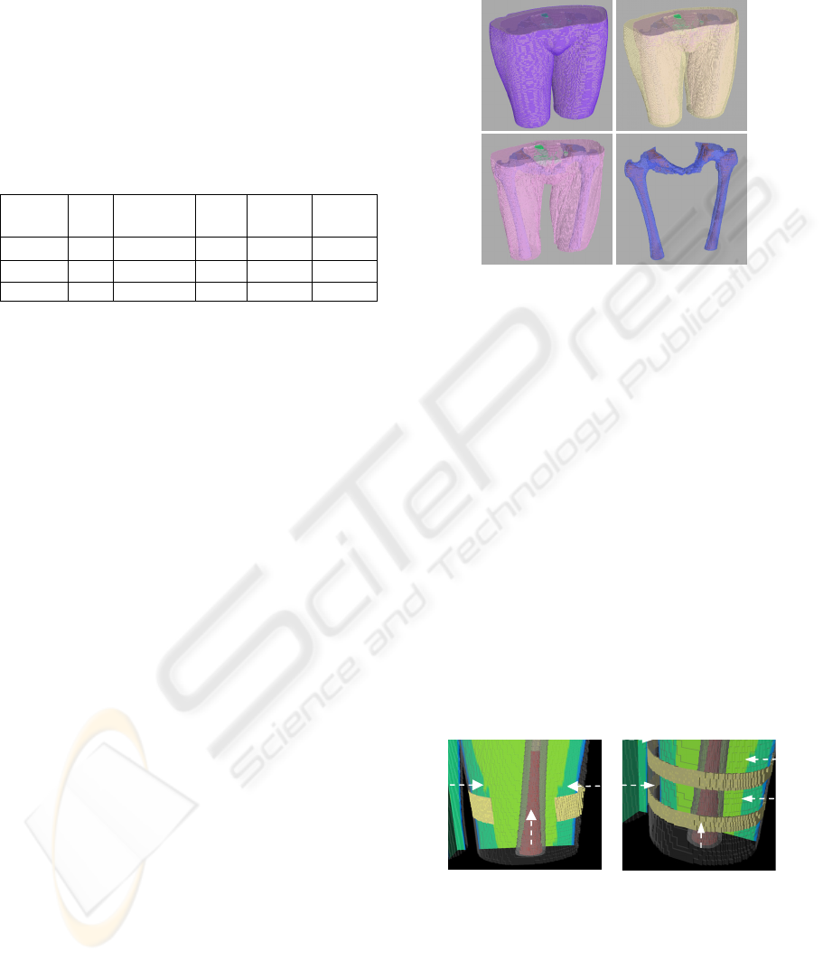
element analysis. An example of a segmentation,
consisting of skin, adipose tissue, muscle, bone and
bone marrow is depicted in Figure 2.
2.3 Electrode Placement & Design
Since there are no preliminary results using such a
system for a percutaneous osseointegrated implant,
we selected four widely variable electrode
configurations for testing. Small electrodes were
designed with patient compliance in mind, since the
device should not restrict ambulation or daily
activity.
Figure 2: Hierarchical label maps constructed in Seg3D
for Patient 2. The completed femoral mapping was
composed of skin (A), adipose tissue (B), musculature
(C), bone (D) and bone marrow (D).
The SCIRun (software.sci.utah.edu) software
package was utilized for electrode design because it
supports interactive electrode placement and
simulation. The configurations selected consisted of
a one patch electrode, two patch electrodes, one
continuous band and two continuous bands (Figure
3). External electrode bands were applied on the
residual limb of the patient and were 1.6 cm in
thickness. Electrode patches were placed as a strip
covering approximately half the diameter of the leg
and were 3 cm in thickness. Lastly, the percutaneous
implants were set to match the size of the cavity of
the bone marrow to represent proper implant fit and
fill, since gaps in excess of 50 μm may lead to
fibrous encapsulation without bone ingrowth
(Bloebaum, Bachus, Momberger, & Hofmann, 1994;
Hofmann, Bachus, & Bloebaum, 1993).
Figure 3: Electrode configurations modeled to determine
optimal performance for amputees. The electrode
configuration is shown from patient 2. A two patch setup
was changed to a one patch setup by removing the medial
electrode (A). A double band electrode was altered to a
single band configuration by removing one band and
centering it amongst the implant area (B). Electrode size
and position are illustrated with arrows.
Patient Sex Amputee Age
Height
[cm]
Weight
[kg]
1 M No 60 185.4 79.9
2 F No 28 157.5 50.1
3 F Yes 80 152.4 45.5
A
B
C
D
B
A
BIODEVICES 2009 - International Conference on Biomedical Electronics and Devices
180

2.4 Finite Element Analysis
In order to predict electric fields from exogenous
voltage potentials, label maps and electrodes were
modeled using a hexahedral mesh that consisted of
approximately 1.7 million elements. The elements
were treated as piecewise homogenous, ohmic and
isotropic, and were assigned conductivities using
previously published values and estimations by the
investigators (Chiu & Stuchly, 2005; Gabriel, Lau,
& Gabriel, 1996; Stinstra et al., 2007) (Table 2).
Because tissue behaves inherently electrolytic,
treating the models with DC conductivities was
considered to be an important factor (Grimnes &
Martinsen 2008).
Electrodes were incorporated in the finite element
meshing and assigned a constant potential difference
of 9 volts between the skin electrode and
osseointegrated implant, a selection based on
expected tissue resistivity. Using an iterative solver,
the potentials in the finite element models were
computed for the three patients and four electrode
configurations.
Table 2: Conductivity values assigned to segmentations.
Tissue Type Conductivities [S/m]
Skin 0.26
Muscle 0.25
Adipose 0.09
Organ 0.22
Cortical Bone 0.02
Bone Marrow 0.07
2.5 Data Analysis
In order for an electrode configuration to be deemed
acceptable, a uniform homogenous field around the
implant interface was required for bone growth.
Therefore, histograms were computed for about
6000 elements in the immediate area encompassing
the bone implant interface. The results were
analyzed using maps of electric field strength that
show the variability of the electric field within the
leg.
3 RESULTS
Interactive placement of electrodes allowed for
various computational simulations. Figure 4
illustrates one example of the differences between
patients. The figure depicts cross sections for three
different patients, where the color scale indicates the
strength of the local field. The corresponding
histogram (right) represents the electric field
strength of the 6000 elements surrounding the
implant site and shows the homogeneity of the field.
The histograms showed a broad variation among
patients, some producing normal Gaussian
distributions and others with broad or skewed peaks
and thus a higher than random level of homogeneity.
The complete set of histograms used for analysis is
listed subsequently in Figure 5.
4 DISCUSSION
The necessity for patient specific models with a
percutaneous electrical stimulation device was
confirmed in the study. The distribution of electrical
potentials at the implant-bone interface varied across
subjects due to variations in anatomy and the
presence of an amputation. While creating “artificial
amputees” using a segmentation program was
straightforward and permitted robust computation,
histograms of electric field strength confirmed that
electrical metrics changed dramatically when
compared to a known amputee. While the shape of
the histograms tended to be bell shaped, the position
of the peaks were often skewed depending on the
electrode configuration and patient. The results
clearly showed that the 1 patch electrode generates
the smallest electric field in the bone-implant
interface, while the 2 band electrode configuration
generated the highest field for the same applied
potential, suggesting that proper electrode placement
could improve efficiency.
Due to the limited quantity of patients in the
study, a strong correlation was not established
relating patient demographics with voltage
potentials. However, the highest voltage gradients
mapped during simulations were consistently from
subject 2, a patient who was in the best physical
condition. The increased electrical field was likely
caused by the reduction in the diameter and
thickness of adipose tissue in the subject’s residual
limb, since adipose tissue would raise resistivity and
impede current flow.
While an optimal electrical configuration may
not have been established for the patient population
collectively, two bands appeared to produce the
most homogenous electrical field distributions
between 1-10 V/cm. Minor adjustments would be
required if the device were used clinically to account
for the varying anatomy of patients, spatial location
of topical electrodes and may be confirmed with CT
files and computational modeling.
DEVELOPMENT OF AN ELECTRICAL STIMULATION DEVICE FOR OSSEOINTEGRATED AMPUTEES - A Novel
Approach for Expediting Skeletal Attachment and Rehabilitation
181
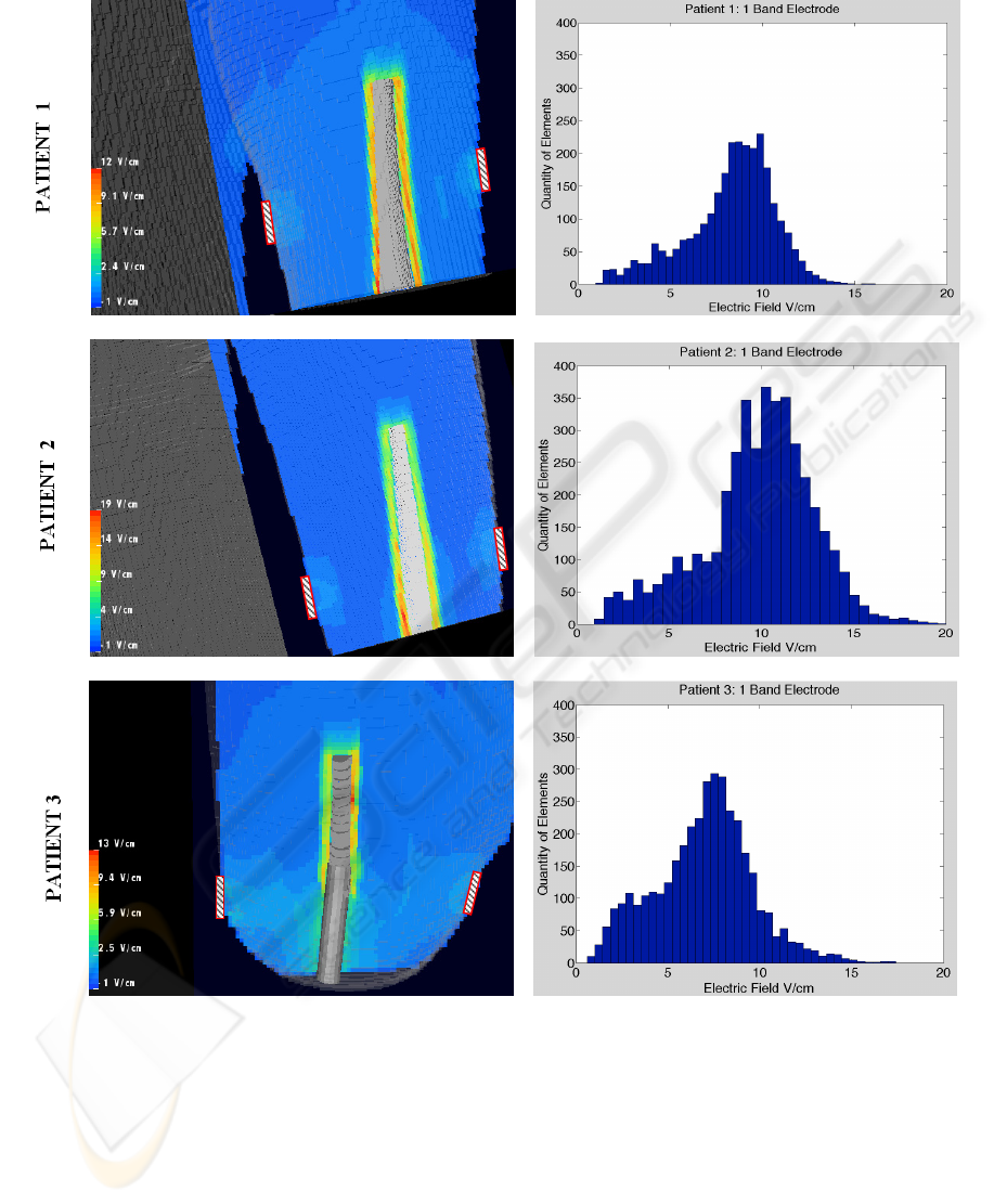
ELECTRIC FIELD
Figure 4: Sample distributions of the electric field strength surrounding the implant. The color map reflects the strength of
the electric field in a cross section through the lower part of the limb. External electrode placements were illustrated as
rectangular objects on the outside of the residual limb. The results were for an 18 centimeter percutaneous implant that was
interactively inserted into the medullary canal of adult patients. The histograms on the right represent the distribution of the
electric field strength in the volume next to the implant.
While the initial target of the exogenous
electrical stimulation system utilizes an orthopedic
implant as a functional cathode, it may also reduce
the potential for superficial and deep infections by
preventing additional surgical procedures to remove
implanted devices as seen with older fracture
healing models (Lavine & Grodzinsky, 1987).
However, the success of the system is dependent on
numerous factors including hydration levels,
quantity of soft tissue and the material type selected
for the orthopedic implant. In order for this novel
technology to be beneficial, a balance must be
BIODEVICES 2009 - International Conference on Biomedical Electronics and Devices
182
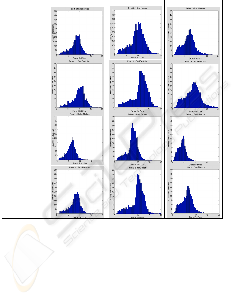
Electrode Type Patient 1 Patient 2 Patient 3
1 Band Electrode
2 Band Electrodes
1 Patch Electrode
2 Patch Electrodes
Figure 5: Comparison between patients and electrode configurations. The results confirm the requirement for individual
patient modeling. Distributions of electric fields were not homogenous in each case and would require manipulation of the
applied voltage potential to attain uniform bone ingrowth.
attained between obtaining a desired electric field
and the host tissue reaction which may occur with
varying implanted metals. Titanium alloy was
selected as the cathode in this model (3x10
6
S/m)
since it is regarded as the one of the most
biocompatible material type for total joint
replacements and has low thermal conductivity to
protect tissue necrosis from heat generation (Agins
et al., 1988; Beder & Eade, 1956; Emneus &
Gudmundsson, 1967). However, if clinicians and
engineers require an altered rate of electron
propagation, the material can be exchanged
(Grimnes & Martinsen, 2008) or porosity altered but
careful attention should be paid to ensure the
material does not illicit a foreign body response.
Utilizing electrical stimulation for older
amputees is a critical aspect which must be explored
as well. Bone mass is maximum a decade after
skeletal growth ceases but decreases significantly by
the eighth and ninth decade (Buckwalter, Glimcher,
Cooper, & Recker, 1995). As long bones change
confirmation with age, the endosteal diameter tends
to increase more rapidly than the periosteal diameter
which could lead to implant loosening (Lane &
Vigorita, 1983). This problem coupled with the
reduction of strain on bones by weaker muscles may
DEVELOPMENT OF AN ELECTRICAL STIMULATION DEVICE FOR OSSEOINTEGRATED AMPUTEES - A Novel
Approach for Expediting Skeletal Attachment and Rehabilitation
183

contribute to debilitating diseases such as
osteoporosis and osteopenia (Lane & Vigorita,
1983) and require additional treatment options.
However, controlled electrical stimulation and
mechanical loading may act as a synergistic catalyst
of bone ingrowth (Spadaro, 1997) and maintain host
bone bed integrity with elderly patients using an
osseointegrated electrical implant system.
Establishing tools for enhancing skeletal
attachment may assist with reducing the length of
rehabilitation required for an osseointegrated
procedure. Current programs require 2 to 24 months
of rehabilitation (Branemark, Branemark, Rydevik,
& Myers, 2001), a lengthy time period to ensure
uniform ingrowth. Because of the slow biological
process of skeletal attachment, loading at the
implant interface would be restricted for several
months after the operative procedure (Hofmann,
Bloebaum, & Bachus, 1997). However, using an
electrical stimulation system may enhance ingrowth
and allow patients to return to earlier ambulation.
4.1 Limitation
Since the conductivity of a titanium implant
significantly exceeded that of cortical bone, the
current densities at the implant interface should be
modeled to ensure localized tissue heating does not
occur, which may lead to patient discomfort or
potential tissue necrosis. Computational modeling of
current density fields are attainable with the given
software package and will be utilized in future work.
Additional efforts with be paid to altering the
porosity of the titanium implant and determining the
effect on the predicted electric fields since porosity
and conductivity are inversely related and may
affect the model as well (Ke et al., 2007).
5 CONCLUSIONS
The simulations developed for the proposed
biomedical device may have the capabilities of
expediting skeletal attachment by increasing
osteoblast migration. Computation modeling has
effectively shown that 1-10 V/cm electric fields may
be generated using the implant as a functional
cathode and topically applied anode band and
patches. Implementing computational models may
be the first step to resolving the classic problem with
electrical stimulation which is the inability to define
current pathways in the human body (Chakkalakal &
Johnson, 1981; Noda & Sato, 1985).
Patient specific modeling was effective for
attaining values that may be osteogenic at the
implant site, but wide variations in electric field
distributions shown in histograms reaffirm the need
to evaluate each case specifically. However, in order
to determine the accuracy of finite element analysis,
the quantity of subjects will be increased in the
future work to determine if an electrode
configuration could be optimized for patients with
percutaneous osseointegrated implants. Additional
model validation of electrically enhanced
osseointegration will be assessed using a small in
vivo animal model based on computational evidence
in future work.
ACKNOWLEDGEMENTS
This material is based upon research supported by
the Office of Research and Development,
Rehabilitation R&D Service, DVA SLC Health Care
System, Salt Lake City, Utah; the Albert & Margaret
Hofmann Chair and the Department of
Orthopaedics, University of Utah School of
Medicine, Salt Lake City, Utah. Additional technical
support for the simulations was provided by the
Center for Integrative Biomedical Computing of
Scientific Computing and Imaging Institute and was
made possible in part by software from the
NIH/NCRR Center for Integrative Biomedical
Computing, P41-RR12553-07.
REFERENCES
Agins, H. J., Alcock, N. W., Bansal, M., Salvati, E. A.,
Wilson, P. D., Pellicei, P. M., et al. (1988). Metallic
wear in failed titanium-alloy total hip replacements. J.
Bone Joint Surg. [Am.], 70-A(3), 347-356.
Albrektsson, T., Branemark, I.-I., Hansson, H.-A., &
Lindstrom, J. (1981). Osseointegrated titanium
implants. Acta Orthop Scand, 52, 155-170.
Albrektsson, T., & Albrektsson, B. (1987).
Osseointegration of bone implants. A review of an
alternative mode of fixation. Acta Orthop Scand,
58(5), 567-577.
Beder, O. E., & Eade, G. (1956). An investigation of
tissue tolerance to titanium metal implants in dogs.
Surgery, 39(3), 470-473.
Bloebaum, R. D., Bachus, K. N., Momberger, N. G., &
Hofmann, A. A. (1994). Mineral apposition rates of
human cancellous bone at the interface of porous
coated implants. J Biomed Mater Res, 28(5), 537-544.
BIODEVICES 2009 - International Conference on Biomedical Electronics and Devices
184

Branemark, P. I. (1983). Osseointegration and its
experimental background. J Prosthet Dent, 50(3), 399-
410.
Branemark, R., Branemark, P. I., Rydevik, B., & Myers,
R. R. (2001). Osseointegration in skeletal
reconstruction and rehabilitation: a review. J Rehabil
Res Dev, 38(2), 175-181.
Brighton, C. T. (1981). The treatment of non-unions with
electricity. J Bone Joint Surg Am, 63(5), 847-851.
Buckwalter, J. A., Glimcher, M. J., Cooper, R. R., &
Recker, R. (1995). Bone biology. J Bone Joint Surg
Am, 77(2), 1276-1289.
Chakkalakal, D. A., & Johnson, M. W. (1981). Electrical
properties of compact bone. Clin Orthop Relat
Res(161), 133-145.
Chiu, R. S., & Stuchly, M. A. (2005). Electric fields in
bone marrow substructures at power-line frequencies.
IEEE Trans Biomed Eng, 52(6), 1103-1109.
Emneus, H., & Gudmundsson, G. (1967). Final report on
clinical testing of titanium. Acta Orthop Scand, 372-
373.
Ferrier, J., Ross, S. M., Kanehisa, J., & Aubin, J. E.
(1986). Osteoclasts and osteoblasts migrate in
opposite directions in response to a constant electrical
field. J Cell Physiol, 129(3), 283-288.
Friedenberg, Z. B., Zemsky, L. M., Pollis, R. P., &
Brighton, C. T. (1974). The response of non-
traumatized bone to direct current. J Bone Joint Surg
Am, 56(5), 1023-1030.
Gabriel, S., Lau, R. W., & Gabriel, C. (1996). The
dielectric properties of biological tissues: III.
Parametric models for the dielectric spectrum of
tissues. Phys Med Biol, 41(11), 2271-2293.
Grimnes, S. & Martinsen O. (2008). Bioimpedance and
Bioelectricity Basics. Amersterdam: Academic Press.
Hagberg, K., & Branemark, R. (2001). Consequences of
non-vascular trans-femoral amputation: a survey of
quality of life, prosthetic use and problems. Prosthet
Orthot Int, 25(3), 186-194.
Hofmann, A. A., Bachus, K. N., & Bloebaum, R. D.
(1993). Comparative study of human cancellous bone
remodeling to titanium and hydroxyapatite coated
implants. J. Arthroplasty, 8(2), 157-166.
Hofmann, A. A., Bloebaum, R. D., & Bachus, K. N.
(1997). Progression of human bone ingrowth into
porous-coated implants. Acta Orthop. Scand., 68(2),
161-166.
Ke, Z., Cheng-Feng, L., & Zhen-Gang, Z. (2007).
Measurement of Electrical Conductivity of Porous
Titanium and Ti6Al4V Prepared by the Powder
Metallurgy Method.. Chin. Phys. Lett., 24(1), 187-190.
Lane, J. M., & Vigorita, V. J. (1983). Osteoporosis. J
Bone Joint Surg Am, 65(2), 274-278.
Lavine, L. S., & Grodzinsky, A. J. (1987). Electrical
stimulation of repair of bone. J Bone Joint Surg Am,
69(4), 626-630.
Noda, M., & Sato, A. (1985). Appearance of osteoclasts
and osteoblasts in electrically stimulated bones
cultured on chorioallantoic membranes. Clin Orthop
Relat Res (193), 288-298.
Spadaro, J. A. (1997). Mechanical and electrical
interactions in bone remodeling. Bioelectromagnetics,
18(3), 193-202.
Stinstra, J. G., Jolley, M., Callahan, M., Weinstein, D.,
Cole, M., Brooks, D. H., et al. (2007). Evaluation of
different meshing algorithms in the computation of
defibrillation thresholds in children. IEEE Engineering
in Medicine and Biology Conference.
Tortora, J. & Nielsen M. (2008). Principles of Human
Anatomy (11
th
ed). United States: John Wiley & Sons.
Williams, D. F. (1982). Biocompatibility of Orthopedic
Implants. Volume I. In D. F. Williams (Ed.), CRC
Series in Biocompatibility (pp. 141-195). Liverpool:
CRC Press, Inc.
DEVELOPMENT OF AN ELECTRICAL STIMULATION DEVICE FOR OSSEOINTEGRATED AMPUTEES - A Novel
Approach for Expediting Skeletal Attachment and Rehabilitation
185
