
SYNCHRONIZING AN X-RAY AND
ANESTHESIA MACHINE VENTILATOR
A Medical Device Interoperability Case Study
∗
David Arney
†
, Julian M. Goldman
‡
, Susan F. Whitehead
‡
and Insup Lee
†
†
University of Pennsylvania, Philadelphia, PA, U.S.A.
‡
MD PnP Program, CIMIT, Cambridge, MA, U.S.A.
Keywords:
MDPnP interoperability, Plug-and-play, Interoperable interconnected medical devices, X-ray ventilator, For-
mal methods, Verification model, Checking apnea, Patient safety.
Abstract:
When a x-ray image is needed during surgery, clinicians may stop the anesthesia machine ventilator while the
exposure is made. If the ventilator is not restarted promptly, the patient may experience severe complications.
This paper explores the interconnection of a ventilator and simulated x-ray into a prototype plug-and-play
medical device system. This work assists ongoing interoperability framework development standards efforts
to develop functional and non-functional requirements and illustrates the potential patient safety benefits of
interoperable medical device systems by implementing a solution to a clinical use case requiring interoper-
ability.
1 INTRODUCTION
Medical devices are a key element in the modern
health care environment. They assist medical staff by
automatically measuring physiologic parameters such
as blood pressure, oxygen level, and heart rate, or ac-
tively influence these parameters by means of infu-
sion pumps for analgesia and insulin or ventilators for
breathing support. Almost all modern medical care
rely on electronic medical devices.
Despite the pervasive use of medical devices
throughout modern health care, most devices work
on their own and in isolation. In contrast, interop-
erable devices would allow connections for sharing
patient data, device status, and enabling external con-
trol, even between devices from different manufactur-
ers. Such interoperability would lead to clear bene-
fits for the care provider and the patient such as more
accurate assessment of the patient’s health and error-
resilient systems through safety interlocks, closed-
loop control, and automatic hot swappable backups.
To realize these benefits, the MD PnP program
at the Center for Integration of Medicine & Innova-
∗
This research was supported in part by NSF CNS-
0509327, NSF-CNS-0610297, NSF CNS-0720703, and
NSF CNS-0834524.
tive Technology at the Massachusetts General Hospi-
tal (CIMIT.org) has been developing techniques and
standards to facilitate medical device interoperability
via MD PnP (Medical Device Plug-and-Play), similar
to the plug-and-play of PC devices.
This paper describes a prototype MD PnP case
study that was conducted for two purposes: (1) for
the MD PnP program to extrapolate functional and
non-functional requirements for the interoperability
standards in progress, and more importantly, (2) to
develop a demo interoperable medical device system
which would illustrate the benefits of the work by im-
plementing a solution to a clinical use case requiring
interoperability.
The rest of the paper is organized as follows. Sec-
tion 2 describes the clinical use case which motivated
this case study. Our problemstatement and challenges
are in Section 3. Section 4 describes the details of our
system implementation, and Section 5 tells how we
modeled and verified the system and generated code
from the model. Finally, our conclusions are in Sec-
tion 6.
52
Arney D., M. Goldman J., F. Whitehead S. and Lee I. (2009).
SYNCHRONIZING AN X-RAY AND ANESTHESIA MACHINE VENTILATOR - A Medical Device Interoperability Case Study.
In Proceedings of the International Conference on Biomedical Electronics and Devices, pages 52-60
DOI: 10.5220/0001537100520060
Copyright
c
SciTePress

2 CLINICAL USE CASE
This project was driven by a specific clinical use case.
This use case was documented by the Anesthesia Pa-
tient Safety Foundation to illustrate a potential safety
problem with the way x-ray images are usually taken
during surgery.
A 32-year-old woman had a laparoscopic
cholecystectomy [gall bladder removal] per-
formed under general anesthesia. At the sur-
geons request, a plane film x-ray was shot dur-
ing a cholangiogram [bile duct image]. The
anesthesiologist stopped the ventilator for the
film. The x-ray technician was unable to re-
move the film because of its position beneath
the table. The anesthesiologist attempted to
help her, but found it difficult because the
gears on the table had jammed. Finally, the
x-ray was removed, and the surgical proce-
dure recommenced. At some point, the anes-
thesiologist glanced at the EKG and noticed
severe bradycardia. He realized he had never
restarted the ventilator. This patient ultimately
expired. (Lofsky, 2004)
It is common practice to stop the anesthesia ma-
chine ventilator for a short time during surgery when
this type of x-ray is performed. This ensures that the
patient’s chest and abdomen are not moving when the
exposure is made, thus providing a sharper image.
This does not harm the patient provided that the ven-
tilator is restarted promptly. Difficulties arise only if
the ventilator is not restarted for some reason. This
kind of problem can be mitigated by using intercon-
nected devices. If the anesthesia machine ventilator
can synchronize with the x-ray, then it is no longer
necessary to manually stop the ventilator to make the
exposure.
Synchronization between a camera and external
devices like a flash is not new. Typically, the cam-
era sends a trigger signal to the flash at the right time.
Similarly, the ventilator could synchronize with the
x-ray machine. Since ventilators are not built to send
synchronized signals to x-ray machines, we designed
our system to have a third device which sits between
the ventilator and x-ray, reads status messages from
the ventilator, and makes the decision about when to
trigger the x-ray. This third component is called the
supervisor and is described in detail in Section 4. Sys-
tems which synchronize x-rays and ventilators have
been built in the past, see for instance (Langevin et al.,
1999), but these systems must be built one at a time
for specific devices and are limited to experimental
use. Ventilators and x-ray machines are manufac-
tured by many companies. Cross-manufacturer inter-
operability would allow synchronized systems to be
built from any combination of devices that support
the functionality. The aim of the MD PnP program
is to develop techniques and standards that facilitate
medical device interoperability in order to allow such
systems to be easily assembled and used clinically.
3 PROBLEM STATEMENT AND
CHALLENGES
Our goal was to explore the safety and engineering
issues involved in building a system that would al-
low the x-ray machine to take a clear image of the
patient without the need to turn off the ventilator. Fur-
thermore, we wanted to build a system which would
illustrate the benefits of interoperability in the med-
ical domain. Interoperable medical devices are de-
vices which are capable of connecting to each other
to share data or to allow external control. Such de-
vices must have an external interface, and the design
of these interfaces is the subject of several ongoing
standards processes such as ISO/IEC 11073, Health
Level 7 (HL7), and others. The use case we addressed
specifically requires interoperability supporting exter-
nal control. The implementation we developed is not
intended to be used clinically. This project is essen-
tially a research platform for understanding the core
issues with interfacing these devices in this particular
use case.
Most medical devices currently manufactured are
not designed to be interoperable. The challenges we
faced in building this system are generally faced by
anyone trying to connect medical devices and are a
major reason such interconnection is not more com-
mon. Medical devices generally have proprietary in-
terfaces which are only documented in technical man-
uals or other material not openly available. We were
fortunate to have the cooperation of Dr¨ager, the man-
ufacturer of the ventilator we used. The interface of
the ventilator was designed to be used for diagnosis
of machine faults and to send data to the electronic
medical record, not as a source of real-time status in-
formation. Thus, it runs at a relatively slow rate, and
the low maximum sample rate (5 - 10 samples per sec-
ond) was the limiting factor in designing our control
algorithm.
A further challenge in interconnecting medical
systems is proving the safety of the resultant system.
Safety is defined as freedom from unnecessary risk,
where risks are unmitigated hazards. FDA provides
guidance on risk minimization for medical devices.
(U.S. Department of Health and Human Services,
Food and Drug Administration, Center for Drug Eval-
SYNCHRONIZING AN X-RAY AND ANESTHESIA MACHINE VENTILATOR - A Medical Device Interoperability
Case Study
53

uation and Research (CDER), Center for Biologics
Evaluation and Research (CBER), 2005) The risk as-
sessment process starts with a hazards analysis or fail-
ure modes and effects analysis (FMEA). These docu-
ments gather potential hazards and their mitigations,
that are used in writing requirements and safety prop-
erties. The risk analysis process and how we used
hazards to derive safety properties with which to ver-
ify the system is described in Section 5.
Our development process started with informal
system requirements which were used to build a state
machine model of the desired system behavior. We
checked this model for safety properties using model
checking software and then generated code from the
model to produce the supervisor.
4 SYSTEM DESCRIPTION
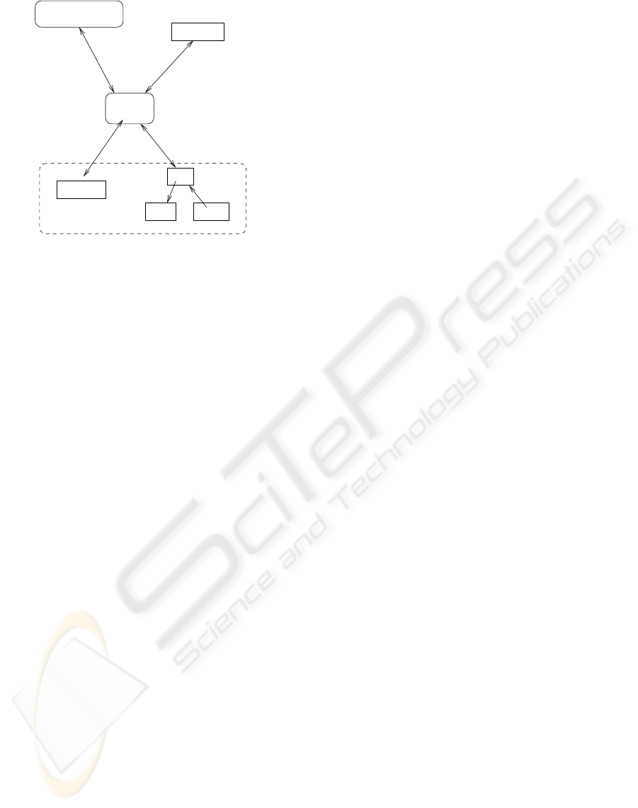
Figure 1 shows the overall architecture of our ap-
proach. This architecture follows closely that of the
draft standard for integrating the clinical environment
(hereafter referred to as ICE) (ASTM F29 WK19878,
2008). The major components are a set of medical
devices, a network controller, a supervisor, the pa-
tient, and a caregiver. Medical devices connect to
each other and the supervisor through the network
controller. The devices’ connections to the network
controller may go through physical adapters and data
format converters if their connectors and formats are
not directly compatible. The network controller may
also connect to an external network such as a hospital
information system. The supervisor runs the control
software for the system. Supervisor software for our
system is the subject of Section 4.2. The supervisor
hosts the user interface for the caregiver and may also
contain a data logger, which records network activity
and information from the devices.
MD PnP requires three phases of operations each
with its own safety, security, and functional require-
ments. The first phase is device discovery and con-
nection establishment, when devices are first con-
nected to a MD PnP network. When a new device
is connected to the network, the device’s capabilities
need to be communicated to the rest of the system.
The second phase is normal operation of the plug-
and-play system. During this phase, the devices trans-
mit data they produce and receive commands or data
from other parts of the system. The final phase is
disconnection. When devices are removed from the
system, the supervisor must decide how to respond.
If the device was necessary for continued operation
of the supervisor program, then the supervisor might
notify the user and shut down. If the device was not
Figure 1: Conceptual Architecture Overview.
necessary, the supervisor might be able to continue
operating in a limited manner.
Our system implementation, which follows the
conceptual architecture, is shown in Figure 2. The
devices we used were a Dr¨ager anesthesia machine
ventilator and a simulated x-ray machine. The role of
network controller and adapter is filled by the Live-
Data RTI software program. LiveData Inc. is a com-
pany which produces software to integrate medical
devices for common display data. We worked with
LiveData to connect the ventilator and simulated x-
ray. Their software translates the proprietary medical
device formats and makes the data available through
a single interface.
The supervisor program runs on the same com-
puter as the LiveData RTI software. Finally, the pa-
tient was represented with a physical lung simulator
consisting of a bellows and spring. While a simple
lung simulator does not capture all the nuances of a
real patient, it is sufficient for this application. Lung
movement is the factor we can control in taking a
clear x-ray, and a supervisor which can synchronize
with a simulated lung can be expected to do the same
with a real patient.
Our demo is not a full MD PnP system. It is
an interconnected medical device system rather than
an interoperable system. An interconnected system
is one in which devices are functionally connected
through an interface. It differs from an interoperable
system in that the devices are hard-coded. The sys-
tem is built around specific devices and will not oper-
ate with other, similar devices. It also does not fully
implement the three phases described above. The
demo is designed to illustrate the possibilities of in-
terconnected systems and show the kinds of systems
which interoperability would permit. It is not pos-
sible at this time to build a fully interoperable MD
PnP system, since the standards are still under de-
velopment. We believe that limited systems such as
this demo still have value in identifying functional
and non-functional requirements for the standards in
BIODEVICES 2009 - International Conference on Biomedical Electronics and Devices
54
Supervisor
Server
ModBus /
Ethernet
Logitech IF /
USB
SOAP /
Ethernet
MediBus /
Serial
PLC
Light Button
Webcam
Simulated X−Ray
Ventilator
LiveData
Figure 2: Overview of the System.
progress and illustrating the benefits of the interoper-
ability work.
4.1 Hardware
The system consists of three major hardware compo-
nents. These are an anesthesia machine ventilator, an
x-ray machine, and a supervisor computer. The venti-
lator breathes for the patient by pumpinggas into their
lungs and allowing them to exhale on their own. The
x-ray machine takes radiographs, and the supervisor
coordinates the actions of the other components. Each
of these devices has its own physical interface and
communication protocol, all of which are different.
Medical devices are not generally developed with the
intention of interconnection. Any external interfaces
which are present are usually used for logging sta-
tus information or debugging. There is presently lit-
tle incentive for manufacturers to follow standards in
building these interfaces, and few standards for them
to follow. Thus, a wide range of interfaces are found
on various devices.
A fourth component is the LiveData server, which
translates formats between the other devices. The
LiveData server communicates with the anesthesia
machine ventilator using Dr¨ager’s MediBus protocol
over a 9600 baud serial line, with the x-ray machine
using the Modbus protocol over ethernet, and with the
supervisor using SOAP on HTTP on TCP/IP over eth-
ernet.
The x-ray machine is simulated using a PLC con-
troller, a webcam, a small red light, and a pushbut-
ton. The PLC allows the light to be turned on and
off and the pushbutton’s status to be read over ether-
net. The webcam is a standard USB webcam which is
controlled using proprietary software.
The supervisor computer, LiveData server, and
PLC are connected with a standard ethernet switch.
In our demo, the supervisor software and LiveData
server were usually run on the same computer.
4.2 Software
The system’s software is divided between the supervi-
sor and the LiveData server. The supervisor controls
the other devices in the system - it correlates infor-
mation from the other devices and makes the deci-
sion when to trigger the x-ray. Supervisors in gen-
eral are responsible for implementing the parts of the
system which are specific to a particular clinical sce-
nario. The supervisor checks to see whether the re-
quired devices are present, collects data from the var-
ious connected devices, and sends commands to the
devices according to the particular scenario. For this
demo, the supervisor gathers data from the ventilator
and sends the signal to trigger an x-ray exposure.
The LiveData server receives SOAP requests from
the supervisor and translates them into requests to
individual devices in their proprietary formats, then
takes the replies from the devices and formats them
as SOAP responses.
The development of the supervisor software is de-
scribed in more detail in Section 5.
4.3 SOAP
The SOAP interface is used for communication be-
tween the supervisor and the LiveData server. A typi-
cal SOAP transaction goes as follows:
1. the user requests the list of variables from the
LiveData server
2. they use the generic get or set methods to do op-
erations on those variables
3. the server receives the command, translates it to
the Dr¨ager MediBus protocol used for the ventila-
tor, and sends the command along
4. the ventilator sends its response to the server,
which translates it and passes the response to the
user
5. the response is returned in an XML wrapper
which contains typing information for the re-
turned values
SOAP is a standard protocol for web services. We
used it here primarily because it was supported by the
LiveData program. It worked well enough for this
application, which had relatively slow data rates and
small amounts of data being passed, but it does have
appreciable overhead. All queries and responses are
SYNCHRONIZING AN X-RAY AND ANESTHESIA MACHINE VENTILATOR - A Medical Device Interoperability
Case Study
55

passed as XML messages which need to be generated
on the sending side and parsed when received.
Another issue was the latency of the SOAP server.
Some of the latency is inherent in encoding and de-
coding XML messages and in passing the messages
through a translator instead of directly sending them
from one device to another. Additional latency in our
demo system resulted from a commonly used conges-
tion control method. When many small packets are
sent over a TCP/IP network, the data being sent is a
small portion of the transmitted packet - most of the
packet is taken up with headers. This can lead to the
network becoming congested when small packets are
sent quickly.
Nagle’s algorithm (Nagle, 1984) is used to con-
catenate these small packets together to reduce over-
all network overhead at the expense of delayed mes-
sage delivery. The data in many small packets can
be bundled into one large packet, reducing the over-
head but increasing the transmission time of the early
packets. In this context, we had plenty of bandwidth
and were much more concerned about the timely de-
livery of messages, so turning off this feature greatly
reduced the latency of the SOAP server.
4.4 Synchronization Algorithms
The supervisor uses information from the ventilator to
decide when to trigger the x-ray. The synchronization
algorithm defines exactly how this decision is made.
Figure 3 shows the respiratory cycle graphed as pres-
sure over time. The pressure increases until the end
of inspiration (at time Tinsp after start of breath), at
which point it drops off quickly through expiration.
There is usually a pause between the end of exhalation
and the start of the next breath. For this case study,
we want to support taking an x-ray when the ’lung’
was not moving significantly. This occurs when the
patient is relatively still at the peak of inspiration or
between the end of expiration and the start of the next
breath. An exposure is possible if the time the patient
is still exceeds the time needed for the exposure plus
the latency between triggering the x-ray and the actual
exposure.
Pressure
Start of Breath Start of Breath
Tinsp
1 / Frequency
Time
Figure 3: Respiratory Cycle.
4.4.1 Synchronization Method 1: Dead
Reckoning
The first method used to determine when to trigger
the x-ray is simple dead reckoning using the time of
last breath, time of inspiration, and frequency. The
variables used for this method are shown in Figure 4.
All times are in seconds.
name description
T
now
current time
T
lb
time of last breath
T
nb
time of next breath
T
δ
a small offset time to accommodate jitter
T
trigger
time to send trigger signal to the X-ray
T
exp
time of X-ray exposure
freq frequency, breaths / minute
flow instantaneous flow rate
Figure 4: Variables for dead reckoning.
If we know the time of the start of the last breath
and the frequency of breathing, then it is trivial to cal-
culate the time of the start of the next breath.
T
nb
= T
lb
+ 60/ freq (1)
There is probably time to trigger the x-ray just be-
fore start of the next breath, as long as the patient has
finished exhaling before the start of the next inhala-
tion.
T
trig
= T
nb
− T
exp
− T
delta
(2)
We can check whether the patient has actually fin-
ished exhaling by sampling the instantaneous flow
rate just before the start of the next breath. If it is
close to zero, then the patient is not inhaling or exhal-
ing and is still enough to allow taking the x-ray.
1. Get values of the variables T
now
, T
lb
, freq
2. Calculate T
trig
3. Sleep for T
trig
− T
now
seconds
4. Wake up and sample flow
5. If flow = 0, trigger X-ray
else, start over
This method of synchronization makes many as-
sumptions. The most critical assumption is that the
respiratory frequency is not going to change between
the last breath and the next one. If it does, or if the
system setup changes in other ways, this method of
synchronization will not work. The check of instanta-
neous flow rate should prevent the system from trig-
gering the x-ray when the patient is moving, but the
system may not be able to take an image in situations
BIODEVICES 2009 - International Conference on Biomedical Electronics and Devices
56

where a different synchronization method would al-
low an exposure.
4.4.2 Synchronization Method 2: Dynamic
Another way to calculate the trigger time is to sam-
ple the real-time flow rate rapidly enough to build a
picture of the flow graph. We experimented with two
techniques for doing this. The variables used in the
following descriptions are listed in Table 5.
name description
flow instantaneous flow rate
T
flow
time of last flow sample
S
current
value of current flow sample
T
current
time of current flow sample
S
last
value of last flow sample
T
last
time of last flow sample
slope calculated slope value
Threshold slope threshold
Figure 5: Variables for dynamic synchronization.
We originally envisioned sampling at a high
enough rate to be able to integrate the total flow vol-
ume by multiplying the sampled flow rate by the time
interval of the samples. This would allow the supervi-
sor to trigger the x-ray at the right time no matter what
changes were made to the ventilator’s programming
or how the patient reacted. However, the ventilator
was not able to provide samples at a high enough rate
to enable this method to be used. The SOAP server
and interface introduced additional latency and jitter
into the samples, which further reduced their useful-
ness for this purpose.
Our second idea was to use the slope of the flow
signal to find when inspiration is about to end. This
meant taking two or more samples, calculating the
rate of change of the flow rate between them, and
triggering when this rate of change was low enough.
The problem we ran into here is that the flow graph
tails off very rapidly, making it unlikely that we would
get even a pair of samples in the short time when the
breath is about to end. The low sample rate made this
problem worse.
1. prime S
last
, T
last
, S
current
, T
current
with two consec-
utive samples
2. S
last
= S
current
3. T
last
= T
current
4. S
current
= flow
5. T
current
= T
flow
6. slope = S
current
− S
last
/T
current
− T
last
7. if slope < Threshold and flow is near 0, trigger
x-ray
else loop back to 2.
In the end, we found that dynamic synchroniza-
tion is possible only at relatively low respiratory rates
- under 8 to 10 breaths per minute. The dead reck-
oning method functions at much higher rates, up to
approximately 25 to 30 bpm depending on the other
ventilator settings. The supervisor program for our
demo checks the respiratory rate and chooses whether
to use the dynamic or dead reckoning method accord-
ingly.
4.5 Alarms
The system should not trigger the x-ray if the venti-
lator has active alarms. The ventilator will take care
of displaying the alarm condition to the caregiver and
sounding alarms, so the supervisor just has to detect
that the ventilator has active alarms and not trigger the
x-ray on that respiratory cycle. It does this by getting
a summary of all active alarms and warnings from the
ventilator. If the list of active alarms is not empty,
then the supervisor will not trigger the x-ray. This
technique is easy to implement and covers the most
common situation where the alarm sounds sometime
before the supervisor decides to trigger the x-ray. This
is sufficient for the demo, but an implementation with
a real x-ray machine and a real patient would have
to take into account factors such as the alarm being
raised after the supervisor checks the alarm status but
before the exposure is made.
In the case where this happens, many conditions
which would cause a ventilator alarm will not affect
the synchronization algorithm. These include alarms
like low gas levels, overpressure, some sensor fail-
ures, etc. Any alarm that does not indicate an unex-
pected change in ventilator settings will not stop the
supervisor from being able to synchronize. Alarms
for major mechanical malfunctions are very rare, but
would indicate conditions where we would not want
an exposure to be made - though any failure which
stopped the ventilator from operating would mean
that the patient’s chest was not moving. The prob-
lem with taking an exposure during an alarm is not
that the image would be blurred, but that the safety of
any caregivers responding to the alarm could be com-
promised. Caregivers are also protected by the use of
a ’dead man switch’ that the x-ray technician holds
during the exposure. If the switch is released, the x-
ray will not be taken. The time interval where there
was an active alarm and the exposure was being made
would be a fraction of a second, but this should be
taken into account in the risk management process.
SYNCHRONIZING AN X-RAY AND ANESTHESIA MACHINE VENTILATOR - A Medical Device Interoperability
Case Study
57

Any system using a real x-ray machine would also
need to take into account alarms from the x-ray, and
any system using medical devices which are capable
of pushing alarms rather than having them polled (as
we did with this ventilator) would also need to con-
sider possible race conditions between the alarm han-
dling and synchronization parts of the supervisor.
5 MODELING, VERIFICATION
AND CODE GENERATION
The software for the supervisor is the key element of
the system. The supervisor is the new piece which
facilitates communication between the other devices.
As was described in Section 4.2, the supervisor’s role
in this demo is to gather data from the ventilator, de-
cide when to trigger the x-ray, and send the signal to
the x-ray machine at the correct time. The supervi-
sor interacts with the caregiver to get input such as
whether to make the exposure during inspiration or
expiration and to provide the caregiver with status in-
formation and, ultimately, with the x-ray image.
The functioning of the supervisor program is crit-
ical to the safety of the system, so we devoted a sig-
nificant amount of time and effort to ensuring its cor-
rectness.
The supervisor software development process
started with gathering informal requirements. These
requirements were collected during discussions with
caregivers and biomedical engineers and included
functional requirements such as “when the exposure
is made, the red light on the x-ray box should light
up” and safety requirements like “the caregiver’s x-
ray trigger button must be held down for the x-ray ex-
posure to be made”. These requirements were refined
and expanded upon throughout the development pro-
cess. For instance, when we started development we
did not know that we would need a dead-reckoning
synchronization algorithm in addition to the dynamic
method and thus did not include any requirements
about when the supervisor should use one or the other
of these techniques.
A state machine model of the supervisor was built
and then verified to meet essential safety properties.
We used the model to generate Java code which then
ran the demo. This development process is described
in more detail in the following sections.
We began by modeling the supervisor program as
an extended finite state machine (EFSM). This format
was chosen because it is expressive enough to capture
the behavior of the program and tools are available
to automatically translate the EFSM specification into
the input languages of a number of tools.
Verification. Once the system was modeled as a
state machine, we used a tool to translate it into the
input format for the model checker UPPAAL. The
model checker was used to simulate the system, to
test the system for general properties like deadlock,
and to test more specific properties. These activities
suggested changes to the EFSM specification, and the
process went though several iterations. Eventually,
we produced an EFSM specification which satisfied
all the safety requirements.
The safety requirements for the system were gath-
ered by talking with clinicians and working though
an informal hazard analysis process. For a device in-
tended for use with patients, this process would be
much more thorough.
The primary hazard introduced by this system is
triggering the x-ray at the wrong time. This could po-
tentially endanger the x-ray technician or other clini-
cians. Triggering the x-ray when the patient is mov-
ing will result in a blurred x-ray and the need to take
another exposure, meaning additional radiation expo-
sure for the patient. Another hazard is that an image
might not be taken even though it is possible. This is
less significant, since the system will inform the clin-
ician that the exposure was not possible and try again
on the next breath. The exposure is delayed slightly,
but this is a small cost compared to that of a failed ex-
posure. The EFSM model of the system was checked
for structural properties like deadlock (that the sys-
tem can’t get ’stuck’) and for specific safety proper-
ties. These focused on when the x-ray is triggered,
since this is the single safety-critical action the sys-
tem takes. We checked that the trigger signal was sent
only at the correct time (as described in the algorithms
in 4.4.1 and 4.4.2) and that the system would not trig-
ger unless the flow rate reported by the ventilator was
near zero.
AG xray = exposing implies T
now
= T
nb
− Texp− T
δ
(3)
Formula 3 is used for checking the system when
it is being used to make an exposure at the peak
of expiration (the lung is empty) in dead reckoning
mode. This specification is in linear temporal logic
(LTL) and it says that whenever the x-ray machine
is in a state where it is exposing (AG xray = expos-
ing) the current time must be the time of the next
breath minus the exposure time minus a small offset
(T
now
= T
nb
− Texp − T
δ
). This means that if there
is any possible way that the EFSM could have the x-
ray in the state ’exposing’ when it is not that time, the
model checker will show it as a counterexample. Sim-
ilar formulas are used for checking exposure times for
BIODEVICES 2009 - International Conference on Biomedical Electronics and Devices
58

inspiration.
AG xray=exposing implies flow <= flow threshold
(4)
Formula 4 states that when the x-ray is exposing,
the instantaneous flow rate must be less than the flow
threshold. This threshold is defined to be low enough
that the lung will not be moving enough to blur the
image, but also high enough to allow an exposure
when there are very small movements.
Implementation Generation. The final EFSM
specification was used to automatically generate Java
code which was used in the demo implementation.
The demo includes a handwritten GUI frontend which
is the user interface and the supervisor application,
which is largely generated code. The generated code
interacts with some handwritten functions which per-
form low-level actions. For instance, the model sim-
ply uses values like flow, while the generated code
replaces references to such variables with calls to
handwritten library functions which actually provide
the values.
Demo. The demo starts with a screen describing the
clinical use case. This is followed by giving the user
a choice of taking an image at the peak of inspira-
tion (when the lungs are full) or the peak of expira-
tion (when the lungs are empty). The user is asked to
confirm their choice and taken to a screen describing
the image-taking process. The user is asked to play
the role of an x-ray technician and to pick up a physi-
cal button which they will hold while the exposure is
made. In a non-synchronized x-ray, this button would
trigger the x-ray directly. In our system, the button is
held down to give the system permission to make the
exposure. The clinician holds the button for several
seconds while the system waits for the lung to reach
the proper phase of respiration and the system checks
to make sure the button is held before taking an im-
age. If the clinician decides that it is not safe to make
an exposure (e.g., if someone walks into the room),
they can simply release the button and no exposure
will occur. This allows us to keep a human in the loop
as an additional safety precaution. Assuming the but-
ton is held down, when the lung reaches the proper
phase the exposure is made and the webcam image is
displayed on the screen.
The system consisted of many components from a
variety of sources, written in several languages. The
main difficulty in implementing the demo was inte-
grating these diverse components into a single, func-
tional system. As was described in Section 4, the
system was tied together using LiveData and SOAP.
While there were significant disadvantages to this
approach (especially in terms of latency), we were
successful in making a working demo. This demo
was shown at the CIMIT Innovation Congress and
as a Scientific Exhibit at the American Society of
Anesthesiologists annual meeting and presented at the
High Confidence Medical Devices, Software and Sys-
tems and Medical Device Plug-and-Play Interoper-
ability workshop (Arney et al., 2007).
6 CONCLUSIONS
We successfully built a system which was able to syn-
chronize the ventilator with a simulated x-ray ma-
chine, demonstrating that the approach is feasible. In
the process, we learned lessons for building more gen-
eral systems. These include the importance of recog-
nizing the limitations of device interfaces in the su-
pervisor algorithm design and the need to have super-
visors which can respond to the changing settings of
the devices. We had two synchronization algorithms,
one which was more accurate but only usable at low
breath rates and a less accurate but faster algorithm
for high breath rates. We used formal methods in the
development of the supervisor and have presented a
methodology for ensuring that the integrated device
systems meet their specified safety properties.
This work started with an unfortunate use case,
resulting from the lack of a respiratory pause feature
on the ventilator and the ventilator’s inability to syn-
chronize with the x-ray machine. The exposure that
our demos brought to this problem has led to a pro-
posed change to the international anesthesia worksta-
tion standard. Hopefully in the future such changes
and the introduction of safe, inter-connected systems
will help to improve patient safety.
ACKNOWLEDGEMENTS
We would like to thank the following people who
were involved in creating the x-ray ventilator syn-
chronization demo. Without their contributions, this
work would not have been possible.
Steve Boutrus, Tufts Medical School
Philippe Cortes, Compiegne Univ. of Technology,
France
Jennifer Jackson, BWH Biomedical Engineering
Shankar Krishnan, MGH Biomedical Engineering
Ersel Llukacej, LiveData, Inc.
Heidi Perry, Draper Laboratory
Tracy Rausch, DocBox, Inc.
SYNCHRONIZING AN X-RAY AND ANESTHESIA MACHINE VENTILATOR - A Medical Device Interoperability
Case Study
59

Jeff Robbins, LiveData Inc.
Rick Schrenker, Biomedical Engineering
Dan Traviglia, Draper Laboratory
Sandy Weininger, U.S. Food and Drug Administra-
tion
REFERENCES
Arney, D., Goldman, J., Lee, I., Llukacej, E., and White-
head, S. (2007). Use Case Demonstration: X-Ray /
Ventilator. In High Confidence Medical Devices, Soft-
ware, and Systems and Medical Device Plug-and-Play
Interoperability, 2007, page 160.
ASTM F29 WK19878 (2008). New Specification for
Equipment in the Integrated Clinical Environment -
Part I: General Requirements for Integration.
Langevin, P. B., Hellein, V., Harms, S. M., Tharp, W. K.,
Cheung-Seekit, C., and Lampotang, S. (1999). Syn-
chronization of Radiograph Film Exposure with the
Inspiratory Pause. Am. J. Respir. Crit. Care Med.,
160(6):2067–2071.
Lofsky, A. S. (2004). Turn Your Alarms On! APSF
Newsletter, 19(4):41–60.
Nagle, J. (1984). Request for Comments: 896, Congestion
Control in IP/TCP Internetworks. Technical report,
Ford Aerospace and Communications Corporation.
U.S. Department of Health and Human Services, Food and
Drug Administration, Center for Drug Evaluation and
Research (CDER), Center for Biologics Evaluation
and Research (CBER) (2005). Guidance for Indus-
try Development and Use of Risk Minimization Ac-
tion Plans. Technical report, Office of Training and
Communication, Division of Drug Information.
BIODEVICES 2009 - International Conference on Biomedical Electronics and Devices
60
