
MODELLING OF SAW BIOSENSORS
Marija Hribšek, Slavica Ristić, Zdravko Živković
Goša Institute, Milana Rakića 35, Belgrade, Serbia
Dejan Tošić
Faculty of Electrical Engineering, Bulevar kralja Aleksandra 73, Belgrade, Serbia
Keywords: SAW devices, SAW filters, biosensors.
Abstract: New approach in surface acoustic wave (SAW) biosensor’s modelling is presented. Biosensor is modelled
as a three port network. The model is general and can be used also in the case of transponder type of sensor.
The closed form solutions for transfer function and input admittance at the electrical port of SAW devices
with uniform transducers based on complex equivalent circuit are presented. Transfer function and input
admittance in two different cases are calculated and compared with the experimental results showing very
close agreement.
1 INTRODUCTION
Surface acoustic waves (SAW) were discovered in
1885 by Lord Rayleigh, and are often named after
him: Rayleigh waves. A surface acoustic wave is a
type of mechanical wave motion which travels along
the surface of a solid material. Rayleigh showed that
SAWs could explain one component of the seismic
signal due to an earthquake, a phenomenon not
previously understood. The velocity of acoustic
waves is typically 3000 m/s, whish is much lower
than the velocity of the electromagnetic waves. A
basic SAW device consists of two interdigital
transducers (IDTs) on a piezoelectric substrate such
as quartz. The IDTs consist of interleaved metal
electrodes which are used to launch and receive the
waves, so that an electrical signal is converted to an
acoustic wave and then back to an electrical signal
(Morgan,1985)
The basic application of the SAW device is as
delay line. Central frequency and the bandwidth are
determined by the IDT`s geometry and the substrate
type. The IDT geometry is capable of almost endless
variation, leading to a wide variety of devices.
Starting around 1970, SAW devices were developed
for pulse compression radar, oscillators, and
bandpass filters for domestic TV and professional
radio. In the 1980s the rise of mobile radio,
particularly for cellular telephones, caused a
dramatic increase in demand for filters. New high-
performance SAW filters emerged and vast numbers
are now produced, around 3 billion annually. In the
last two decades SAW devices have found numerous
different applications outside their conventional
fields of application: communications and signal
processing. In the last decade considerable work has
been done in the development of SAW sensors of
different types of high quality. SAW filters are used
as temperature, pressure and stress sensors as well as
chemical and biosensors (Seifert, 1994, Pohl, 2000).
At Imperial College in London are working on
implantable and wearable SAW devices for long
term clinical monitoring. Saw sensors are also used
for wireless monitoring in harsh environment. There
are two different types of SAW sensors: transversal
and resonant. In liquids usually SH SAW type of
sensors are used. In the references only analyses in
time domain of the sensors exist. In the frequency
domain only resonant type of SAW sensors are
modelled (Campbell, 1989).
In this paper modelling of transversal SAW
sensors is presented. It is well known that the exact
analysis of SAW devices using surface wave theory
is very complex (Matthews, 1977). Because of that
approximate methods of analysis are developed. The
simplest method of analysis is using delta function
model. It gives the approximate results relatively
376
Hribšek M., Risti
´
c S., Živkovi
´
c Z. and Toši
´
c D. (2009).
MODELLING OF SAW BIOSENSORS.
In Proceedings of the International Conference on Biomedical Electronics and Devices, pages 376-379
DOI: 10.5220/0001544203760379
Copyright
c
SciTePress
fast, but its use is limited to small loads and
substrates with lower coupling constants.
The better approximate methods use equivalent
models for IDTs, where the analysis tools known in
electrical engineering can be applied. In these
methods the accuracy depends on the complexity of
the model. The closed form solutions for transfer
functions and input admittances mostly only for
simple models are given (Matthews, 1977, Morgan,
1985, Smith 1, 1969, Smith 2, 1969, Debnath, 1983,
Hribšek, 1983). In this new algorithm SAW
biosensor is modelled as three port network. The
IDT`s equivalent circuit based on Milsom`s and
Redwood`s equivalent model (Milsom and
Redwood, 1971) is most complex. Using the
symbolic analysis method (Hribšek, 2007) the closed
form solutions for transfer function and input
admittance of the SAW biosensor are derived. The
algorithm is valid for both types of sensors: direct
and transponder types (Pohl, 2000). The algorithm is
verified by two examples: insertion loss and input
admittance are computed and compared with
experimental results. It is also shown that in the case
of the transponder straightforward dependence of the
loss and measured value is obtained.
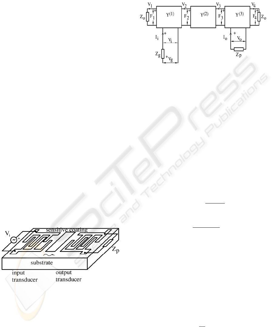
2 THE MODEL
The transversal SAW biosensor can be
schematically presented as in Figure 1: between the
interdigital transducers (IDT) on the top of the
piezoelectric substrate the chemical or bio sensitive
layer is placed.
Figure1: The basic configuration of SAW biosensor.
The surface wave is induced by electrical signal
applied to the input IDT. The output signal (voltage)
is taken from the second IDT. The interdigital
transducers are wideband with uniformly spaced
electrodes. The configuration presented in Figure 1
can be modelled by equivalent electrical scheme
given in Figure 2 where IDT`s are three port
networks and the middle sensing part is a two port
network.
Figure 2: Equivalent electrical model of a saw sensor.
The characteristic acoustic impedance of the
unloaded substrate is Z
o
, and the electrical
impedances of the generator and load, are Z
g
and Z
p,
respectively. Each part is defined by its
corresponding admittance matrix Y
(1)
, Y
(2)
and Y
(3)
.
These matrices are calculated following the
procedure presented in (Hribšek, Tošić). In general
case matricies Y
(1)
and Y
(3)
are different, but usually
in sensors they are equal with small number of
electrodes, thus simplifying the calculations. Since
the circuit is passive for all matrices the passivity
condition: Y
ij
,= Y
ji
, for i
≠
j, is valid. F
i
`s and v
i
`s
denote the electrical equivalents of mechanical
forces and velocities. The elements of Y
(2)
of the
sensing part is given by:
s
jZ
g
yy
θ
cot
)2(
22
)2(
11
==
(1)
s
Z
ecj
y
θ
cos
)2(
12
=
(2)
where
o
ff /
π
θ
=
,
o
f is the central frequency,
s
Z is the acoustic impedance of the sensing part,
and f is the frequency of the input signal.
Now the whole sensor can be represented as an
equivalent two port where one port is the electrical
input of the input IDT and the second port is the
electrical port of the output transducer. The transfer
function of the two port defined as:
g
o
V
V
T =
(3)
can be expressed in the following form:
MODELLING OF SAW BIOSENSORS
377
gg
P
ZYYZY
Z
Y
Y
T
21121122
21
)1)(
1
( −++
−
=
(4)
where Y
ij
are the admittance parameters of the
equivalent two port. Therefore, for the transfer
function determination y parameters should be
found. They are found in several steps. In each step
one partial Y matrix is derived. In the first step
matrix Y`, which connects input voltage and current
with force F
2
and velocity v
2
, is found. Than the
matrix Y`` which gives the relationship between the
input signals and the F
3
and v
3
is determined.
Finally, the Y matrix is derived in terms of
parameters of the matrices Y
(1)
, Y
(2)
and Y
(3)
. The
expressions are in closed form, but very bulky and
that is the reason why they are omitted in this text.
The symbolic circuit analysis method is used. The
obtained relations are general. In the case of SAW
sensors they can be less complex if input and output
transducers are equal. Also if the simpler models of
IDTs are used, the calculation will be easier, but in
any case computer must be used.
For matching purposes, the input admittance
must be determined. It can be expressed in terms of
the y parameters of the input transducer as follows:
2
121111
1112
2
1333
))((
22
yYyYy
YYyy
yyY
so
so
i
−++
+++
−=
(5)
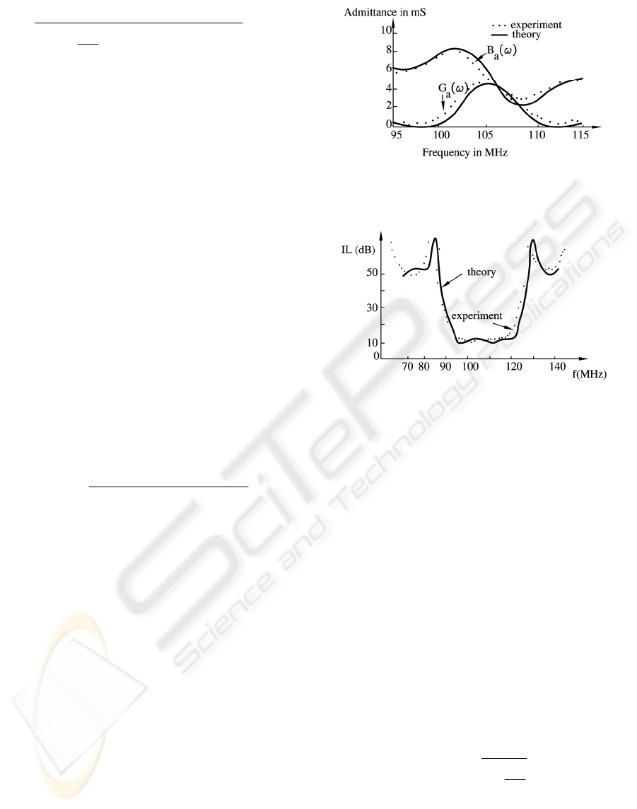
Using the algorithm presented, the computer
program which calculates frequency dependence of
input conductance and susceptance and insertion
loss of SAW device with two uniform transducers
was made. The program was verified by two
examples taken from (Smith et al.1., Smith et al.2).
In these cases the substrate between transducers was
unloaded, e.g.
os
ZZ = . The computed results are
presented in Figures 3. and 4., solid lines. To allow
comparison between the computed and measured
data, the experimental results are also presented in
the same figures, dotted lines.
From Figures 3 and 4 is obvious that
experimental and calculated data are in excellent
agreement, even better than in (Smith et al.1., Smith
et al.2).
Figure 3: Real (G
a
) and imaginary (B
a
) part of the input
admittance.
Figure 4: Calculated and measured insertion loss.
Since the algorithm and computer programs are
verified than can be successfully used in the analysis
or prediction in any particular case in SAW
biosensors. In that case due to the loading of the
sensitive film the acoustic impedance will change
accordingly, and therefore Y
i
and T have to be
changed.
The algorithm is general. It can be also very
efficiently used in the frequency domain analysis of
SAW transponders (Pohl, 2000). SAW transponders
are SAW devices which do not have sensing film
between the transducers. They get the signal
obtained from the actual physical sensor on the
impedance Z
P
. In that case from relation (4) is
obvious that for one device all admittances are
constants and the only variable is Z
P
. Than, since
og
ZZ = ,
os
ZZ
=
, and
oo
RZ = , transfer
function can be expressed as:
P
o
P
Z
R
TZT
+
∝=
1
1
)()(
(6)
where
)(
∝
T denotes the transfer function when Z
P
is infinite. Now two cases can be discussed: when Z
P
is real and when it is of capacitive or inductive type.
BIODEVICES 2009 - International Conference on Biomedical Electronics and Devices
378
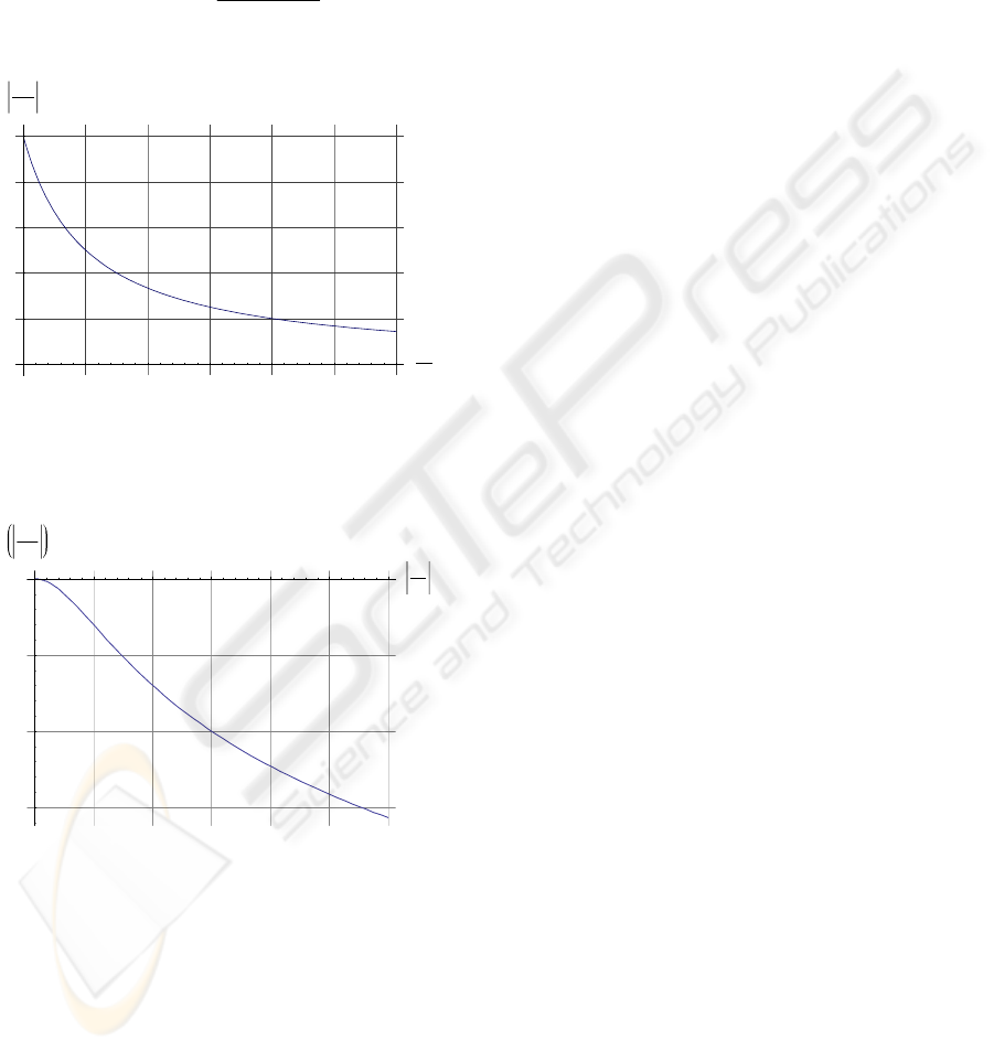
If
Z
P
is real e.g.
PPP
GRZ /1=
=
, ratio of
)(
P
ZT and )(∝T can be represented as in Figure
5.
If the loading is purely inductive or capacitive ratio
of
)(
P
ZT
and )(∝T can be expressed as follows:
oP
P
RjB
TBT
+
∝=
1
1
)()(
(7)
1 2 3 4 5 6
G
p
G
0
0.2
0.4
0.6
0.8
1.0
T
T
in
f
Figure 5: Relative amplitude versus resistive load.
In that case relative insertion loss can be represented
as in Figure 6.
1 2 3 4 5 6
Y
p
G
0
-
15
-
10
-
5
T
T
inf
dB
Figure 6: Relative insertion loss versus load susceptance.
3 CONCLUSIONS
The new developed algorithm is general. It can be
used in frequency analysis of SAW based
biosensors, as well as of SAW transponders. The
efficiency of the presented algorithm is
demonstrated with calculations of frequency
dependence of input conductance and susceptance
and insertion loss of SAW devices with uniform
transducers. The results are compared with
corresponding experimental data showing very close
agreement.
ACKNOWLEDGEMENTS
The authors thank the Ministry of Science and
Technological Development of Serbia for financial
support under the project number 11026.
REFERENCES
Morgan D. P., 1985, Surface Wave Devices for Signal
Processing, Elsevier, London.
Seifert F., Bulst W.E., Ruppel C., 1994, Mechanical
sensors based on surface acoustic waves, in Sensors
and Actuators, A44, pp. 231-239.
Pohl A., 2000, A Review of Wireless SAW Sensors,in
IEEE Transactions on ultrasonics, ferroelectrics, and
frequency control, vol. 47, no. 2, pp. 317-332, (Invited
Paper).
Campbell C., 1989, Surface Acoustic Wave Devices and
Their Signal Processing Applications, Academic
Press, Boston.
Matthews, ed. 1977, Surface Wave Filters, John Wiley,
New York.
Smith W.R., et al, 1, 1969., Analysis of interdigital surface
wave transducer by use of equivalent circuit model, in
IEEE Trans. on MTT, vol.17, No 11, pp.856-864.
Smith W.R., et al, 2, 1969., Design of surface acoustic
delay lines with interdigital transducers, in IEEE
Trans. on MTT, vol.17, No 11, pp. 865-873.
Debnath N., Ajmera J.C., Hribšek M. F., Newcomb R.W.,
1983. Scattering and Admittance Matrices of SAW
Transducers, in Circuits, Systems and Signal
Processing, vol.2., No.2, pp. 161-178.
Hribšek M., Tošić D., 1983, An Improved Algorithm for
Analysis of Uniform SAW Transducers, in Proc. 26
th
Midwest Symposium On Circuits and Systems,
INAOE, Mexico.
Milsom R. F., Reddwood M., 1971, Interdigital
Piezoelectric Rayleigh Wave Transducer: an improved
Equivalent Circuit, in El. Letters, vol.7, p. 217.
Hribšek M., Tošić D., 2007, Symbolic analysis and design
of current-differencing-amplifier filters, in Scientific
Technical Review, vol. LVII, No. 2.
MODELLING OF SAW BIOSENSORS
379
