
A RECONFIGURABLE ARRAY FOR BLIND SOURCE-SEPARATION
ON AN FPGA
Ricardo Escalona, Daniel Herrera and Miguel Figueroa
Department of Electrical Engineering, Universidad de Concepcion, Barrio Universitario S/N, Concepcion, Chile
Keywords:
Blind source-separation, Independent component analysis, InfoMax, Embedded signal processing, Field-
programmable gate arrays.
Abstract:
We present a reconfigurable array which performs blind source separation on a range of field-programmable
gate array (FPGA) devices. Our array uses independent component analysis (ICA) with the InfoMax algorithm
to separate a mixture of signals without an external reference. We describe two configurations of the array,
representing distinct points in the design space. Our experimental results show a performance improvement of
more than one order of magnitude over an optimized software implementation of the algorithm on a computer,
with a power consumption of just 100mW. Our array successfully separates a fetal electrocardiogram (ECG)
mixture into the source signals of mother and fetus, enabling medical analysis on the resulting independent
components.
1 INTRODUCTION
Independent component analysis (ICA) is a signal
processing technique used to recover the original
sources from unknown mixtures captured by spatially
distributed sensors. Due to the weak assumptions im-
posed by ICA on the nature of the original signals, this
technique is widely used to perform blind source sep-
aration on medical applications such as electrocardio-
gram (ECG) and electroencephalogram (EEG) analy-
sis (Zeng et al., 2008; Potter et al., 2002), as well as
speech recognition, face classification, and data com-
munications (Bell and Sejnowski, 1997).
Despite these advantages, most ICA algorithms
require high computational throughput to operate in
real time. Typical software solutions on general pur-
pose computers are large and power hungry, and even
digital signal processors do not meet the power, per-
formance, and cost requirements of embedded and
portable applications. Custom VLSI implementations
usually feature the best power/performance tradeoff,
but they lack the flexibility of software solutions, and
their design cycle is long and expensive.
We present a hardware implementation of the In-
foMax algorithm for ICA on field-programmable gate
arrays (FPGAs). Unlike custom-VLSI circuits, FPGA
can be easily reprogrammed on-site, retaining the
flexibility of software implementations while attain-
ing higher performance and lower power consump-
tion (Anguita et al., 2003). Unlike previous imple-
mentations (Yang et al., 2007; Li and Lin, 2005), we
can target our array at a wide range of devices, trad-
ing size and cost for performance depending on the
requirements of the application.
In this paper, we describe the architecture and tar-
get it at both an entry-level device and a high-end
platform FPGA. First, we describe the InfoMax al-
gorithm. Then, we describe the architecture of the
array and discuss the implementation of key func-
tions in fixed-point arithmetic. We discuss and an-
alyze our design trade-offs for both versions of the
architecture and their impact on circuit area and per-
formance. Finally, we present experimental results on
the separation of mother and fetus EEG signals. The
performance of the array on the entry-level FPGA is
similar to that of an optimized software implementa-
tion on a desktop PC, while the array on the platform
FPGA improves the performance of software imple-
mentation by more than one order of magnitude. Both
arrays dissipate less than 100mW.
2 THE INFOMAX ALGORITHM
As stated in the previous section, Independent Com-
ponent Analysis performs blind-source separation of
an unknown mixture of independent signals. ICA
262
Escalona R., Herrera D. and Figueroa M. (2009).
A RECONFIGURABLE ARRAY FOR BLIND SOURCE-SEPARATION ON AN FPGA.
In Proceedings of the International Conference on Biomedical Electronics and Devices, pages 262-267
DOI: 10.5220/0001551902620267
Copyright
c
SciTePress
Orthogonalization
Weight
update
Forward
computation
Normalization
·
=
u W x
1 1
2 tanh( )·
T
k k k
µ
− −
= + −
W W I u u W
1
1
,
,
j
k
k k k
j
proj
proj
−
=
=
= −
∑
z
z
w z
w z
z z
z w w
j
j
j
=
z
w
z
k
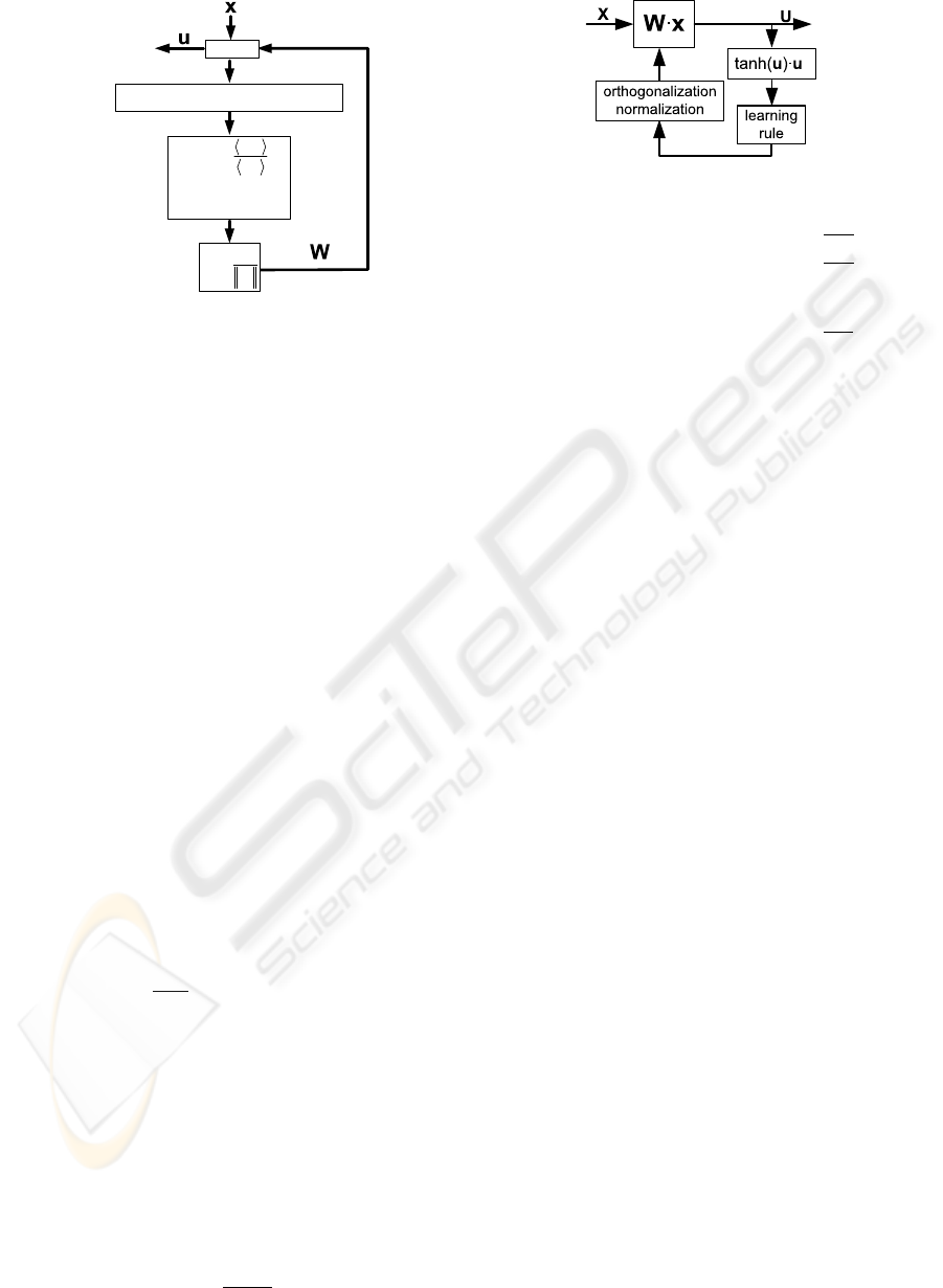
Figure 1: The InfoMax algorithm.
assumes only that the mixture is linear, the origi-
nal sources are statistically independent, and that at
most one of them exhibits a Gaussian distribution.
The technique applies a linear transformation on the
mixed signals and adapts its coefficients to maximize
the statistical independence of the outputs.
There are several algorithms that perform ICA,
but one of the most widely used is InfoMax (Car-
doso, 1997), which separates the sources by minimiz-
ing the mutual information between the outputs. Fig-
ure 1 outlines the data flow of the algorithm. Like
all ICA algorithms, the InfoMax computes the out-
put vector u(k) as the product of the n-input vector
x(k) = [x
1
(k) . ..x
n
(k)]
T
and a weight matrix W(k):
u(k) = x(k)
T
W(k) (1)
where k is the time step. After each block of data (256
samples in our implementation), the algorithm applies
a nonlinear learning rule to update the coefficients of
W. InfoMax maximizes the entropy of the output,
using the learning rule W(k + 1) = W(k) + µ∆W(k),
where µ is the learning rate and
∆W(k) = (I − ϕ(u(k))u
T
)W(k) (2)
is the weight increment at time k, where I is the iden-
tity matrix, ϕ(u) =
∂g(u)
∂u
and g(·) is an invertible and
nonlinear function.
Both the learning rate and the nonlinear function
g(·) are parameters chosen by the designer, and affect
the dynamic and stationary behavior of the algorithm.
One of the most widely used nonlinear functions is
g(u) = tanh(u) ⇒ ϕ(u) = 2tanh(u).
To prevent all vectors of matrix W from converg-
ing in the same direction, the algorithm orthogonal-
izes and normalizes them after each iteration. We use
Gram-Schmidt orthogonalization:
pro j
z
w =
h
w,z
i
h
z,z
i
z
T
Figure 2: Array architecture.
z
1
= w
1
w
1
=
z
1
k
z
1
k
z
2
= w
2
− pro j
z
1
w
2
w
2
=
z
2
k
z
2
k
.
.
.
.
.
.
z
k
= w
k
−
∑
k−1
j=1
pro j
w
j
z
k
w
k
=
z
k
k
z
k
k
(3)
where w
k
are the weight vectors, z
k
are their orthog-
onal projections before normalization,
hi
is the dot
product, and
kk
is the Euclidian norm.
3 THE ARRAY
3.1 Architecture
Figure 2 depicts the general architecture of our hard-
ware implementation of InfoMax. The algorithm ex-
ecutes in three main stages:
• First, an array of hardware multipliers performs a
vector-matrix multiplication to compute the out-
puts following Equation 1. The weight matrix
W
nxn
is stored on on-chip RAM memory blocks.
• Second, for every block of 256 samples, the
output values are used to compute the InfoMax
weight update according to Equation 2, which in-
volves computing the tanh function and a matrix
multiplication.
• Finally, the array applies the updates to the stored
weight matrix, and then normalizes and orthog-
onalizes the weight vectors using Gram-Schmidt
(Equation 3), which require multiplications, divi-
sions, and square roots.
We exploit the available data parallelism both
within each stage, and also between stages using
pipelining. The scheduling of the computations dif-
fers between the two different configurations of the
array, and are explained in more detail in Sections 3.3
and 3.4. First, we discuss the implementation of basic
arithmetic functions that are common to both config-
urations.
A RECONFIGURABLE ARRAY FOR BLIND SOURCE-SEPARATION ON AN FPGA
263
3.2 Basic Functions
The basic operations required by the InfoMax algo-
rithm are multiplication, addition, hyperbolic tangent,
square root, and division. Our current implementa-
tion uses Xilinx FPGAs, which feature 18-bit signed
integer multipliers. Therefore, the input signals, coef-
ficients and most intermediate values are encoded as
18-bit fixed-point quantities (5-bit integer and 12-bit
fractional, plus sign). Addition is performed using
18-bit ripple-carry adders supported directly by the
FPGA hardware with a fast carry chain. We use the
available 18-bit hardware multipliers to compute the
products, selecting the corresponding 18-bit slice out
of the 36-bit result, and performing arithmetic round-
ing to improve resolution.
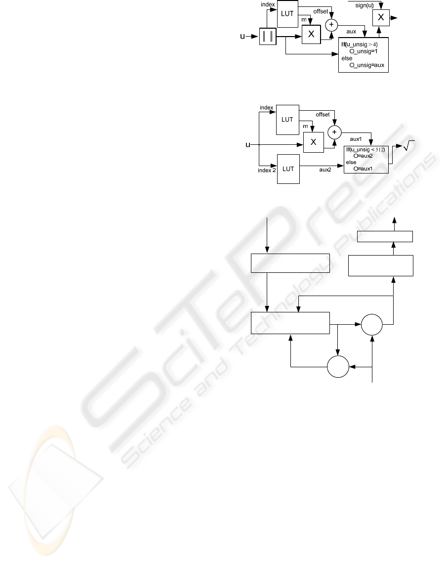
Nonlinear functions such as tanh, division and
square root are not supported by the FPGA hardware,
so they must be implemented by hand. The algorithm
computes the tanh of every output value, therefore
its implementation must be fast. As depicted in Fig-
ure 3(a), we use on-chip block RAM to implement
lookup tables (LUTs) that contain selected values of
the tanh function, and use linear interpolation to ob-
tain intermediate values. Because the function is sym-
metrical, we only store values for positive arguments.
Each of the 512 table entries contains the slope and
offset of a linear segment of the approximation, and
the table is indexed using the 9 most-significant bits
of the absolute value of the argument.
We also use LUTs to compute the square-root
function. The function is smooth for large arguments,
but changes rapidly for small ones. The resolution
of the square root function greatly affects the conver-
gence of the InfoMax algorithm, so the uniformly-
spaced table approach used for tanh is inadequate.
Our solution, depicted in Figure 3(b) is to use two
LUTs : the first table provides an exact value for the
first 512 values of the argument, while the second ta-
ble implements a linear approximation for the rest of
the argument’s 18-bit dynamic range.
The convergence of InfoMax is very sensitive to
the resolution of the division operation. Therefore,
implementing it with LUTs would require extremely
large tables. Instead, we opted for an iterative algo-
rithm which computes the quotient with 18-bit reso-
lution in 24 clock cycles using a series of bit shifts,
comparisons, and subtractions. Figure 3(c) illustrates
the algorithm.
3.3 Fully-Parallel Configuration
The fully-parallel implementation of the algorithm
targets large FPGA devices to maximize performance
tanh( )
u
u
u[16:8]
(a) Hyperbolic tangent.
u
u[16:9]u[7:0]
(b) Square root.
Prenormalize
Partial dividend
Left shift register
Quotient
left shift register
Postnormalize
Initial
Load
A ≥ B
A - B
Recursive
load
Shift/load select
Divisor
B
B
A
A
Shift in
Quotient
Dividend
(c) Division.
Figure 3: Implementation of basic functions.
at the expense of die area. In our current implementa-
tion, we target this configuration to a Xilinx Virtex-II
Pro XC2VP30 platform FPGA, which contains 136
multipliers, 30, 816 logic cells, and 2,448 Kbits of
block RAM. The device also contains two PowerPC
processor cores, which we do not currently use. Our
current implementation reads 4 data streams and pro-
duces 4 output streams.
The fully-parallel array breaks up the algorithm
into four stages, each of them further decomposed in
substages which execute concurrently in a pipelined
fashion. The hardware multipliers ultimately con-
strain how many operations of the algorithm we can
perform in parallel on the chip. Table 1 summarizes
the actions performed by each stage and their resource
utilization. We briefly describe their operation and re-
BIODEVICES 2009 - International Conference on Biomedical Electronics and Devices
264
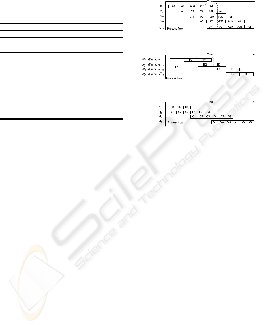
Table 1: Fully-parallel configuration.
Stage Operation Mult.
A1 Read input x
4x1
0
A2 u = W
4x4
·x
4x1
16
A3a Read 4 tanh LUT 0
A3b 4 times: tanh(u
k
) = c
k
+ m
k
·u
k
4
A4 A
4x4
= A
4x4
+ tanh(u
4x1
)·u
T
4x1
16
B1 B
4x4
= I
4x4
− 2·A
4x4
0
B2 D
4x4
= B
4x4
·W
4x4
16
B3 W
4x4
= W
4x4
+ c·D
4x4
4
C1 4 dot products
h
a,b
i
16
C2
h
w,z
i
/
h
z,z
i
0
C3 3 times: z
k
= w
k
−
∑
k−1
j=1
pro j
w
j
z
k
12
D1 a =
∑
4
j=1
z
jk
4
D2 b = sqrt(a) 1
D3 w
k
= z
k
/b 0
lationship to the equations in Section 2:
Stage A - Separation. Computes the output vector
and the tanh of each output element in a 256-
sample block. Stage A1 loads the input vec-
tor from memory, while A2 performs the ma-
trix - vector multiplication x(k)
T
W(k) depicted
in Equation 1. Stages A3a and A3b compute
tanh(u) using the LUTs, and stage A4 accumu-
lates ϕ(u)·u
T
according to Equation 2.
Stage B - Update. Every 256 samples, the array up-
dates the weight matrix W according to the Info-
Max learning rule. Stage B1 computes I −ϕ(u)u
T
in Equation 2, stage B2 completes the computa-
tion of ∆W, and stage B3 applies the weight up-
date.
Stage C - Orthogonalization. Orthogonalizes the
new weights according to Equation 3. Stages C1
performs up to four dot products in parallel, C2
compute the projections, and stage C3 subtracts
them from the original weight vectors.
Stage D - Normalization. Normalizes the weight
vectors. Stages D1 and D2 compute the Euclidean
norm of each vector using multiplies and square-
root operations, and stage D3 divides each weight
vector by its norm.
Figure 4 depicts the schedule of execution of all
four stages in the fully-parallel architecture. The ar-
chitecture uses pipelining to overlap the execution
of different substages for consecutive input vectors.
Thus, in stage A up to five substages are executed si-
multaneously on the array, and the array processes a
new input vector on each clock cycle.
….
...
(a) tanh(u)·u
T
.
(b) Weight update.
(c) Orthogonalization and normalization.
Figure 4: Schedule of fully-parallel configuration.
3.4 Folded Configuration
In order to fit the array into smaller (and thus less ex-
pensive) FPGA devices, we fold each stage of the ar-
chitecture onto itself to process fewer input elements
simultaneously. Thus, instead of performing every
operation of each substage in parallel, we use time-
multiplexing to share multiple hardware resources be-
tween different elements of an input vector. The cur-
rent target device for our folded configuration is a
Xilinx Spartan 3 XC3S1000, which features 24 mul-
tipliers, 17,280 logic cells, and 432 Kbits of block
RAM. A software tool aids the designer in the pro-
cess of folding the architecture based on the available
resources in the target device, and generates the cor-
rect HDL code.
Table 2 shows the stages and resource utilization
of the folded configuration. Compared to Table 1, the
resource utilization has been now reduced to process
only one vector element at a time, while the fully-
parallel configuration processes a entire new vector at
each clock cycle. As a result, the folded configuration
uses approximately 25% of the resouces of the fully-
parallel version, at the cost of extended execution time
and a slightly more complex control structure.
Figure 5 shows the pipelined scheduling of the
operations within each stage in the folded configura-
tion. Stage A now processes a new input vector every
eleven clock cycles. Orthogonalization and normal-
ization take place sequentially, and the division oper-
A RECONFIGURABLE ARRAY FOR BLIND SOURCE-SEPARATION ON AN FPGA
265
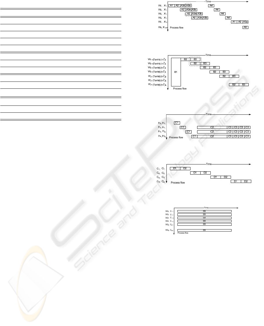
Table 2: Folded configuration.
Stage Operation Mult.
A1 Read input x
4x1
0
A2 u
i4x1
= w
i1x4
·x
4x1
4
A3a Read 1 tanh LUT 0
A3b 1 time: tanh(u
k
) = c
k
+ m
k
·u
k
1
A4 a
i1x4
= a
i1x4
+ tanh(u
4x1
)·u
T
4x1
4
B1 B
4x4
= I
4x4
− 2·A
4x4
0
B2 d
k1x4
= b
k1x4
·w
k4x1
4
B3 w
k4x1
= w
k4x1
+ c·d
k4x1
1
C1 1 dot product
h
a,b
i
4
C2
h
w,z
i
/
h
z,z
i
0
C3 1 time: z
k
= w
k
−
∑
k−1
j=1
pro j
w
j
z
k
4
D1 a =
∑
4
j=1
z
jk
4
D2 b = sqrt(a) 1
D3 w
k
= z
k
/b 0
ation during normalization (D3) is computed simulta-
neously for all weights at the end of the update.
4 EXPERIMENTAL RESULTS
We mapped the fully-parallel configuration of the
array to a Xilinx Virtex-II Pro XC2VP30 platform
FPGA. The maximum clock rate achieved by our im-
plementation is 55.8MHz, corresponding to a critical
path of 18ns. The chip dissipates 103mW of power.
We tested the array on a 4-input experiment of blind
source-separation with InfoMax. The chip is capable
of processing a 256-sample block and update the In-
foMax weights in 7.8µs, corresponding to 431 clock
cycles. The algorithm converges in approximately
7.5ms (less than 1000 block iterations).
The folded configuration mapped onto a Xilinx
Spartan 3 XC3S1000 FPGA exhibits a critical path of
22.3ns, achieving a clock rate of 49.9MHz, and dissi-
pating 93.4mW. On the same 4-input experiment, the
chip processes a 256-sample block in 113µs, corre-
sponding to 5,073 clock cycles. The algorithm con-
verges in less than 110ms in this configuration of the
architecture. Table 3 summarizes the resource utiliza-
tion (excluding multipliers and block RAM) of each
configuration of the array on their corresponding de-
vice.
For comparison purposes, we implemented the In-
foMax algorithm in software on a laptop PC featur-
ing floating-point arithmetic, a dual-core processor
running at 1.73GHz, and 2GBytes of DDR2 RAM.
An optimized C implementation of the InfoMax al-
gorithm running the same experiment used to test the
array, completes one iteration every 90µs, and con-
….
.
.
.
(a) tanh(u)·u
T
.
…...
......
(b) Weight update.
…..
…
.
.
.
(c) Orthogonalization
(d) Normalization (1).
…..
…...
(e) Normalization (2)
Figure 5: Schedule of folded configuration.
verges in 85ms . Thus, the fully-parallel configura-
tion of the array reduces the execution time of the
software implementation by a factor of 11.3. On the
other hand, the execution time of the software version
is smaller than that of the folded array by a factor of
1.3. The power consumption of both hardware imple-
mentations is smaller than the computer by more than
two orders of magnitude.
We tested both arrays on fetal ECG signals. In
this application, spatially-distributed electrodes cap-
ture four mixtures of signals which contain the ECG
of the mother and the fetus. We recorded the results
obtained from both hardware implementations of the
algorithm, and from the software running on a PC.
BIODEVICES 2009 - International Conference on Biomedical Electronics and Devices
266
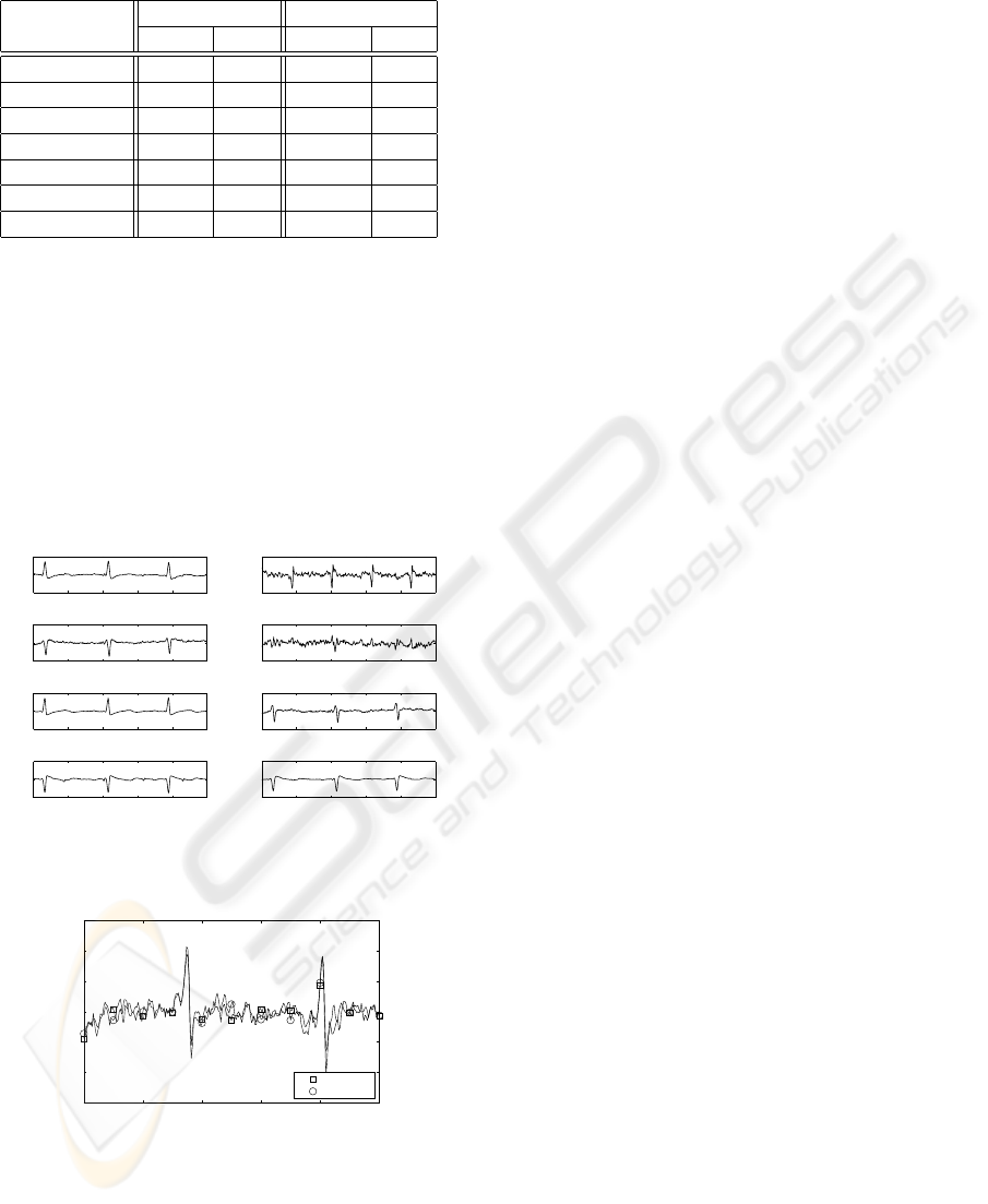
Table 3: Global resource utilization.
Fully parallel Folded
Resource Qty. % Qty. %
Slices 5,115 37% 6,680 86%
Flip Flops 4,010 14% 4,743 30%
Input LUTs 6,686 24% 11,009 71%
IOBs 44 7% 43 24%
Block RAM 1 24% 1 68%
Block ROM 8 2% 5 13%
Multipliers 91 67% 13 54%
Because they are based on the same architecture, both
arrays produce the same results. Figure 6 shows the
waveforms obtained from the hardware implementa-
tion of the algorithm. The chips successfully produce
the ECG signal of the fetus, two ECG signals of the
mother, and the noise. Figure 7 compares the software
and hardware results for one waveform. We measured
the error of the results produced by the array relative
to the floating-point software implementation. The
RMS value of the error, normalized to the amplitude
of the signal, varies between 0.07% and 0.09%.
0 0.2 0.4 0.6 0.8 1
−1
0
1
(a) Time(Sec)
Amplitude
0 0.2 0.4 0.6 0.8 1
−1
0
1
(b) Time(Sec)
Amplitude
0 0.2 0.4 0.6 0.8 1
−1
0
1
(c) Time(Sec)
Amplitude
0 0.2 0.4 0.6 0.8 1
−1
0
1
(d) Time(Sec)
Amplitude
0 0.2 0.4 0.6 0.8 1
−0.1
0
0.1
(e) Time(Sec)
Amplitude
0 0.2 0.4 0.6 0.8 1
−0.05
0
0.05
(f) Time(Sec)
Amplitude
0 0.2 0.4 0.6 0.8 1
−1
0
1
(g) Time(Sec)
Amplitude
0 0.2 0.4 0.6 0.8 1
−2
0
2
(h) Time(Sec)
Amplitude
Figure 6: (a)-(d): Measured mixtures, (e): ECG - fetus, (f):
Noise, (g)-(h): ECG - mother.
0 0.1 0.2 0.3 0.4 0.5
−3
−2
−1
0
1
2
3
Time(sec)
Normalized Amplitude
Software
Hardware
Figure 7: ECG results - fetus.
5 CONCLUSIONS
We described an array architecture for ICA using the
InfoMax algorithm. The array can be reconfigured
to target a wide range of FPGA devices, represent-
ing different price/performance tradeoffs. We showed
two configurations: a fully-parallel version mapped to
a Xilinx Virtex-II Pro XC2VP30, and a folded imple-
mentation mapped to a Xilinx Spartan-3 XC3S1000.
The parallel array outperforms both the folded config-
uration by a factor of 14.5, and a PC-based software
implementation by a factor of 11.3. Both hardware
arrays consume in the order of 100mW, use 18-bit
fixed-point arithmetic, and achieve a resolution within
0.08% of a floating-point software implementation of
the algorithm. Future and ongoing work includes de-
veloping a software tool to automate the reconfigura-
tion process, and integrating the folded version of the
array on a portable ECG instrument.
ACKNOWLEDGEMENTS
This work was partially funded by grants Fondecyt
1070485 and Milenio ICMP06-67F.
REFERENCES
Anguita, D., Boni, A., and Ridella, S. (2003). A digital ar-
chitecture for support vector machines: Theory, algo-
rithm, and FPGA implementation. IEEE Transactions
on Neural Networks, 14:993–1009.
Bell, A. J. and Sejnowski, T. J. (1997). The ’Independent
Components’ of Natural Scenes are Edge Filters. Vi-
sion Research, 37(23):3327–3338.
Cardoso, J. F. (1997). Infomax and maximum likelihood
for blind source separation. IEEE Signal Processing,
4:112–114.
Li, Z. and Lin, Q. (2005). FPGA implementation of In-
fomax BSS algorithm with fixed-point number repre-
sentation. Neural Networks and Brain, 2:889–892.
Potter, M., Gadhok, N., and Kinsner, W. (2002). Separation
performance of ICA on simulated EEG and ECG sig-
nals contaminated by noise. IEEE Canadian Confer-
ence on Electrical & Computer Engineering, 2:1099–
1104.
Yang, Y., Huang, X., and Yu, X. (2007). Real-time ECG
monitoring system based on FPGA. 33rd Annual Con-
ference of IEE Industrial Electronics Society, pages
2136–2140.
Zeng, Y., Liu, S., and Zhang, J. (2008). Extraction of fetal
ECG signal via adaptive noise cancellation approach.
The 2nd International Conference on Bioinformatics
and Biomedical Engineering, pages 2270–2273.
A RECONFIGURABLE ARRAY FOR BLIND SOURCE-SEPARATION ON AN FPGA
267
