
A RF TRANSCEIVER FOR WIRELESS MONITORING
SYSTEMS OF THE VERTEBRAL COLUMN BEHAVIOUR
J. P. Carmo and J. H. Correia
University of Minho, Dept. Industrial Electronics, Campus Azurem, 4800-058 Guimaraes, Portugal
Keywords: Wireless acquisition system, RF transceiver, Spine deceases, e-health systems.
Abstract: This paper presents a radio-frequency (RF) transceiver designed, using a standard 0.18 µm CMOS process,
for operation in the 2.4 GHz ISM band. The receiver has a sensivity of -64 dBm and consumes 3.5 mW
from a 1.5 V supply. The RF transmitter delivers an output power of +11 dBm (15 mW) with a power
consumption of 45 mW. These features make the RF transceiver suitable to be integrated in microsystems,
where the low-power is a major requirement. The application of these microsystems is to monitoring the
influence of heavy loads, in the behaviour of the vertebral column.
1 INTRODUCTION
The human posture has been an object of studies in
biomechanics, once some deviations of structural
and functional positions induce an unbalanced body.
These deviations usually, affects the vertebral
column and are caused by physical efforts, bad
postures in work, deficiency in sustentation muscles,
infections and congenital causes. The main
pathologies of vertebral column caused by the
referred deviations, are the scoliosis and lordosis.
Sometimes these pathologies appears in children
when they carry the heavy backpacks on the backs,
in this case, it’s very important monitoring the
influence of loads (backpack weight) in vertebral
column behavior. Figure 1 shows an adolescent
female with scoliosis in the vertebral column. Her
rib proeminence is most obvious upon her bending
forward. The radiograph demonstrates a right
thoracic scoliosis. The study of influence of
backpack weighs on the vertebral column of children
is an important issue, that has been worked by many
researchers for years (Palastranga et al, 2002). The
application cited in this work uses the following
approach: applying indirect information, using the
electrical potential generated by the muscles, when
they contract and when they are rest. The technique
which could measure this electrical potential is the
electromyography (EMG). Based on the results of
EMG, combined with the movements of the body,
measured by the accelerometers, it is possible to
know by numerical simulation, the displacement
occurred on the insertions points between the
muscles and the vertebral column (Pato et at, 2007).
Using these values of displacements in a finite
element code, like ANSYS, it is possible to compute
the value of stress field in the vertebral column,
especially it is possible to observe where are the
points more affected and the respective stress value.
Figure 1: An adolescent female with scoliosis.
The radio-frequency (RF) transceiver proposed in
this paper, was designed using a standard 0.18 μm
CMOS process. This process allows to have the
power supply of 1.5 V. The proposed low-
power/low-voltage transceiver, is intended for use in
wireless sensor networks, more specifically, for the
monitoring the influence of heavy loads, in the
behavior of the vertebral column.
281
Carmo J. and Correia J. (2009).
A RF TRANSCEIVER FOR WIRELESS MONITORING SYSTEMS OF THE VERTEBRAL COLUMN BEHAVIOUR.
In Proceedings of the International Conference on Biomedical Electronics and Devices, pages 281-285
DOI: 10.5220/0001555802810285
Copyright
c
SciTePress
~
Local oscillator (LO)
@ 2.4/2.5 GHz
Envelope
detector
IF
(100 MHz)
Filter
Switch
RXD
TXD
LNA
PA
A
2.5 GHz
2.4 GHz
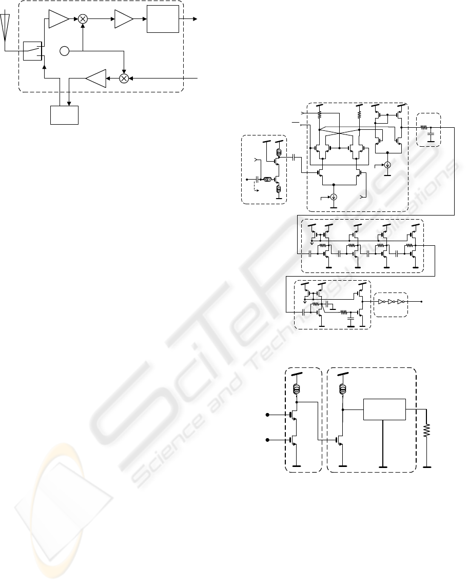
Figure 2: The block schematic of the RF transceiver.
2 TRANSCEIVER'S DESIGN
The transceiver has a receiver, a transmitter, an
antenna-switch and a phase-locked loop (PLL) as
frequency synthesiser. The Figure 2 shows the
architecture of the proposed transceiver, where the
reception is made by means of direct demodulation,
using the technique of heterodyne detection. The
final demodulation step is made with the use of a
envelope detector, applied for an intermediate
frequency of 100 MHz.
The quality requirement for the proposed RF
transceiver is a transmission with a bit error
probability less than 10
-6
(one error for each one
million bits transmitted) with a sensitivity of
-64 dBm, in a transmitted power of +11 dBm using
Amplitude Shift Keying (ASK)
modulation (Carlson et al, 2002). All of these
specifications are useful to make this transceiver
suitable for short range applications (e.g., between
fifty five and sixty meters - #55 / #60 meters), and
obviously, to the target biomedical application,
which will be further explained in the section 4.
2.1 Receiver
The Figure 3 shows the receiver’s front-end
schematic. This circuit has a low-noise amplifier
(LNA) that provides a 50 Ω input impedance, using
a tuned load to provide high selectivity. The
amplified RF signal is directly converted to an
intermediate frequency (IF) with a mixer, followed
by a low-pass filtering and a post-amplifier. The
final downconversion to the base-band is made with
envelope detection.
The low-noise amplifier (LNA) is the first gain
stage in the receiver path. In a LNA, the signal must
be amplified as much as possible, keeping the
signal-to-noise ratio (SNR) as low as possible. This
is achieved with the best noise figure (NF). The
LNA is an inductively degenerated common source
amplifier. The cascoding transistor M
2
is used to
increase the gain, to better isolate the output from
input and to reduce the effect of M
1
’s C
gs
(Yao et al, 2007). The LNA enters in the sleeping
mode, when the current in the polarization stage is
switched off. The same principle applies to the all
subsystems.
LO
Mixer circuit
Bias 4
LO
L
s
L
g
C
b
Bias 1
Input
M
1
M
2
LNA
Ω
=
50
in
Z
L
d
C
b
Bias 3
C
f
R
f
IF filter
Bias 2
Bias 5
M
1
M
2a
M
2b
M
2c
M
2d
M
3a
M
3b
M
3c
M
3d
C
b
C
b
C
b
C
b
R
p
R
p
R
p
R
p
Post-amplifier
Bias 6
Output
stream
Output buffer
C
1
C
2
C
3
R
2
R
1
Envelope
detector
M
3
M
4
M
5
Figure 3: The schematic of the receiver.
M
1
M
2
L
d
1
M
1
L
d2
Class E
PA filter
Antenna
TDX
LO
Class E Power amplifierPA driver
Figure 4: The schematic of the transmitter.
The downconversion to the IF uses a four-quadrant
multiplier Gilbert cell as a mixer. This mixer
performs well with local signals (LO) at 2.5 GHz
and a square shape. The main advantage is the
possibility to use ring-oscillators, rather than tuned
LC, thus, a big on-chip area saving is possible to be
achieved, without a severe degradation in the
phase-noise. Moreover, this don't poses special
cares, because the down-conversion from IF to the
base-base, is made by way of an envelope detection,
whose input signal comes from the output of a low-
BIODEVICES 2009 - International Conference on Biomedical Electronics and Devices
282
pass filter detector. The IF frequency is produced
from the 2.4 GHz RF and from the 2.5 GHz local
frequency. A minimum IF level at the envelope
detector defines the receiver’s sensitivity. This
envelope detector is of active type, e.g., it provides
gain, compared with the conventional topology
using a simple clamping circuit. Thus, the sensitivity
of the receiver is bigger, compared when a passive
detector is used.
2.2 Transmitter
Figure 4 shows the schematic of the transmitter. The
upconversion to the pass-band at 2.4 GHz, is made
by a cascade circuit, comprising transistors M
1
and
M
2
. This circuit combines the transmitted
bitstream (TXD) with local carrier generated in the
frequency synthesizer described further. This circuit
produces an AKS digital signal compatible with the
usage of a switched power amplifier of class E
(Sokal et al, 1975). The external filter that follows
the power amplifier is a typical class E network, and
removes the spectral components around the
2.4-GHz carrier frequency.
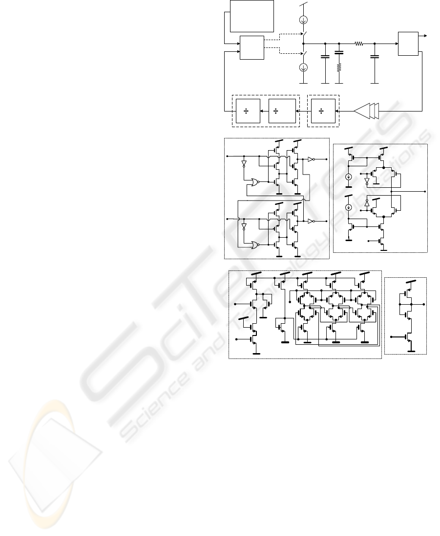
2.3 Frequency Synthesiser
The local generation of the frequency synthesiser is
a phase-locked loop (PLL) with integer division in
the feedback path. The Figure 5 shows the block
diagram of the PLL, which has a reference generator
circuit with a crystal based oscillator at 20 MHz,
followed by a phase-frequency difference
circuit (PFD) without dead zone, a current steering
charge pump (CP) and a third order passive filter.
The passive section output is connected to the VCO,
which generates the desired frequencies of 2.4 GHz
or 2.5 GHz. These frequencies must be divided by
120 or by 125 and connected to the PFD again,
closing the loop. For the TSPC logic, it is required a
rail-to-rail input to work properly. At these
frequencies, the power consumptions are lowest,
when compared with the SCL logic
(Pellerano et al, 2004). In real PFDs there is an
offset around the zero phase difference, and a gain
inversion region takes place for phase differences
higher than 2
π
-Δ rad. In this gain inversion region,
the PFD outputs the wrong control signals increasing
the phase and frequency differences between the
inputs, and the lock time takes a sudden turn for the
worse (Lee et al, 2003). The PFD has a linear gain in
the range [-
π
, +
π
] and a constant gain in the remain
interval. This constant gains increases the bandwidth
of the PLL, making it faster to lock, compared with
those containing other structures (Kim et al, 2005).
20 MHz XTAL
reference
generator
PFD
VCO
F
ref
F
div
Up
Down
I
cp
I
cp
C1 C2
R2
C3
R3 V
control
High-frequency buffers
F
out
2
Static logic
30/32
2
TSPC
a)
Up
Down
F
div
F
ref
PFD
I
Up
I
Down
Down
Up
CP output
Control
V
Charge-pump
b)
Control
V
Bias
VCO
Bias
Bias
Tuning
V
VCO circuit
Control
V
c)
Figure 5: a) The PLL structure, b) the schematic of the
PFD-CP, and c) the schematic of the VCO.
The charge pump (CP) is of current steering type
(Chih-Ming et al, 2002). This circuit avoids the
problems in conventional CPs. In spite of being
switched, the currents are routed from the load to an
alternative path, and from that path to the load. To
finish, the voltage controlled oscillator (VCO) is of
ring type, in order to save on-chip area and because
the phase and frequency errors are not critical in the
used modulation.
3 EXPERIMENTAL RESULTS
For the receiver, simulations shown a sensivity of
-64 dBm and a consumption of 3.5 mW from a 1.5 V
A RF TRANSCEIVER FOR WIRELESS MONITORING SYSTEMS OF THE VERTEBRAL COLUMN BEHAVIOUR
283
supply. The RF transmitter delivers an output power
of +11 dBm (15 mW) with a power consumption of
45 mW. The receiver has a total power consumption
of 3.5 mW for the receiver (1.5 mW for the LNA,
0.6 mW for the down-conversion mixer and 1.5 mW
to the post-amplifier and envelope detector). The
transmitter has the power consumptions in the
following blocks: 2.7 mW in the driver and
41.5 mW in the power amplifier.
2.1 2.2 2.3 2.4 2.5 2.6 2.72.0 2.8
Frequency [GHz]
fs(V
antenna
) [V]
m3
0.5
1.0
0.0
1.5
m3
f
MHz
= 2.4 GHz
fs(V
antenna
) = 1.229 e
+j59.9º
[V]
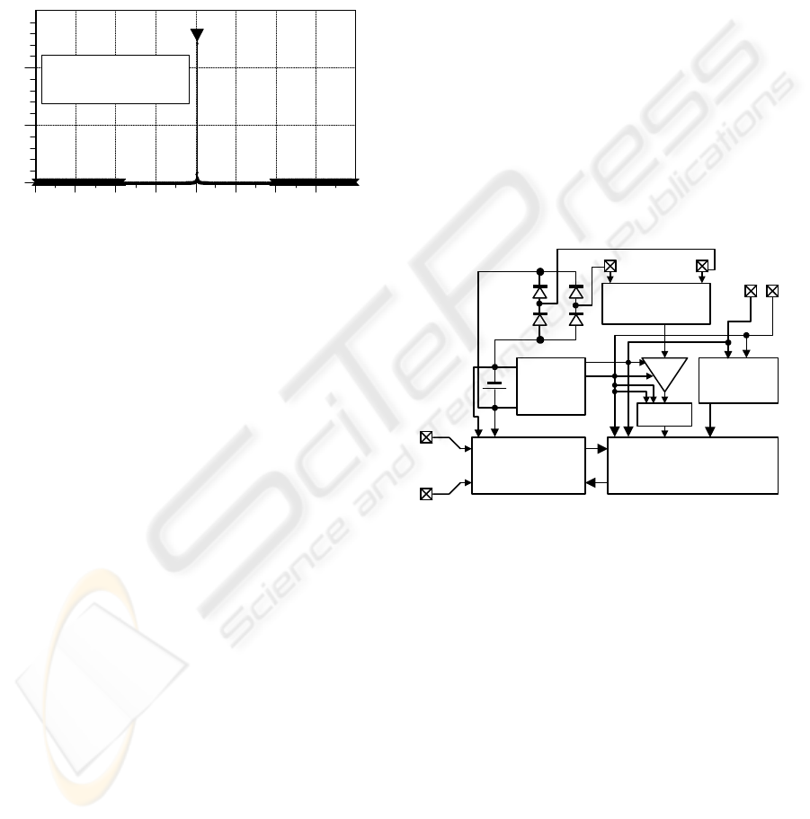
Figure 6: Amplitude spectrum of the amplified signal at
the antenna terminals.
The Figure 6 shows the amplitude spectrum of the
amplified signal at the terminals of an antenna, with
an input impedance of 50 Ω.
4 APPLICATION
The application for microsystems using the
transceiver proposed in this paper, is to make
wireless acquisition modules, in order to allow the
monitoring of heavy loads influence on vertebral
column’s behaviour. Each module makes the
electromyography (EMG), to measure the electric
potentials on the iliocostalis and longissimus
thoracis muscles, and use a dual-axis accelerometer
to get the movements of the body, in order to obtain
the complete behaviour of the vertebral column. The
acquired information is to be transmitted with the
maximum rate of 250 kbps, however, the
simulations shown, that the baud-rate can be
extended without jitter problems, for frequencies up
to 10 Mbps. An analog channel with differential
input connected to the electrodes, is required to
measure the EMG signal, while the remained
channel is to measurements of the patient’s
movements.
The analysis of the EMG signal must be made in the
amplitude domain, thus, before proceeding to the
ADC conversion, it is required a peak detection of
the amplified EMG signal, followed by an
integration (Robertson et al, 2004). This mandatory
process eliminates the fluctuations that characterize
the EMG signals.
The measurements of the motion and the
positioning of the patient’s body is made with the
use of a commercial dual-axis accelerometer of
MEMS type. This chip connects to a commercial
microController by way of an integrated Serial Port
Interface (SPI).
The Figure 7 shows the block diagram of a first
possible prototype, which contain the sensor
interface read-out, the electronics for data
acquisition (amplifications and analog-to-digital
conversion) a micro-controller, and the proposed RF
transceiver. A coin-sized 1.5 V battery will provide
the supply and a commercial DC/DC step-up
converter makes possible to supply the remaining
components of the prototype with different voltage
levels. As it can be seen in this Figure, the anti-static
(ESD) protections are provided by way of power-rail
connected diodes (Ker et al, 2005).
From EMG
electrode
ADC
RF
transceiver
microControler
From
antenna
Interface
(ESD protections)
A
1.5 V
>1.5 V
DC/DC
step-up
2-axis
acelerometer
SPI
interface
Out-supply
Figure 7: Block diagram of the microsystems for use in
wireless modules.
5 CONCLUSIONS
This paper presented a low-power/low-voltage
radio-frequency (RF) transceiver at 2.4 GHz, for
working with a single 1.5 V coin-sized battery.
Simulations shown for this transceiver a
consumption of 3.5 mW in the receive mode and
15 mW of transmitted power, with a power
consumption of 45 mW in the transmitting mode.
These characteristics fulfil the requirements for
short-range communications.
The target application for this transceiver is in
wireless acquisition modules for monitoring of
heavy loads influence on vertebral column’s
behaviour, in order to understand the influence of
BIODEVICES 2009 - International Conference on Biomedical Electronics and Devices
284

heavy loads as a risk factors in the vertebral column,
such as the scoliosis and lordosis. These factors
normally associated to appears in children when they
carry the heavy backpacks on the backs. Thus, it’s of
extremely importance to characterise the influence
of heavy loads (backpack weight) in the vertebral
column behaviour. This solution fits the medical
doctors requirements for an easy placement and
removal of wireless modules. The main advantage of
this solution, is the maintenance of the mobility and
lifestyle of patients during the diagnosis.
The possibility to control the receiver and the
transmitter subsystems, allowing them to be
switched on and off is another advantage of this RF
transceiver. This is a specially important topic of
design, in applications where power efficient
algorithms are mandatory, e.g., in wireless sensors
networks (Enz et al, 2004).
REFERENCES
Carlson, B., et al, 2002, Communication systems: An
introduction to signals and noise in electrical
communications, 4th edition, McGraw-Hill, 2002.
Chih-Ming, H., et al, 2002, A fully integrated 1.5 V
5.5-GHz CMOS phase-locked loop, IEEE Journal of
Solid-State Circuits, Vol. 37, No. 4, pp. 521-525.
Enz, C., et al, 2004, WiseNET: An ultralow-power
wireless sensor network solution, IEEE Computer,
Vol. 37, Nr. 8, pp. 62-70.
Ker, M., et al., 2005, ESD implantations for on-chip ESD
protection with layout consideration in 0.18-μm
salicided CMOS technology”, IEEE Transactions on
Semiconductor Manufacturing, Vol. 18, Nr. 2,
pp. 328-337.
Kim, B., et al, 1005, A 250-MHz–2-GHz wide-range
delay-locked loop, IEEE Journal of Solid-State
Circuits, Vol. 40, Nr. 6, pp. 1310-1321.
Lee, K., et al, 2003, Phase-frequency detectors for fast
frequency acquisition in zero-dead-zone CPPLLs for
mobile communication systems, Proc. of the 29th
ESSCIRC, 16-18, Estoril, Portugal.
Palastanga, N., et al, 2002, Anatomy and human
movement, 4th edition, Butterworth Heinemann,
pp. 445-537.
Pato, M., et al, 2007, A finit element model for squeletical
muscles, Proc. of the CMNE/CILAMCE, 2007.
Pellerano, S., et al, 2004, A 13.5 mW 5-GHz frequency
sinthesizer with dynamic logic frequency divider,
IEEE Journal of Solid-State Circuits, Vol. 39, Nr. 2,
pp. 378-383.
Robertson, D., et al, 2004, Research methods in
biomechanics, Human Kinetics.
Sokal, N., et al, 1975, Class E-A new class of
high-efficiency tuned single-ended switching power
amplifiers, IEEE Journal of Solid-State Circuits,
Vol. 10, Nr. 3, pp. 168-176.
Yao, T., et al, 2007, Algorithmic design of CMOS LNAs
and PAs for 60-GHz radio, IEEE Journal of
Solid-State Circuits, Vol. 42, No. 5, pp. 1044-1057.
A RF TRANSCEIVER FOR WIRELESS MONITORING SYSTEMS OF THE VERTEBRAL COLUMN BEHAVIOUR
285
