
A USEFUL LOGICAL SEMANTICS OF UML FOR QUERYING AND
CHECKING UML CLASS DIAGRAM
Thomas Raimbault, David Genest and St´ephane Loiseau
Leria, University of Angers, 2 bd Lavoisier, 49045 Angers Cedex 1, France
Keywords:
UML, First Order Logic, Knowledge Representation and Reasoning, Model-Based Reasoning, Knowledge
Engineering, Visual Quering, Visual Checking, Positive Constraints, Negative Constrains.
Abstract:
In Knowledge Engineering, UML class diagram is the defacto standard for modeling object oriented systems.
We propose a way for logical reasoning on UML class diagram, concerning querying and checking class
diagram. First, we define an original logical semantics to UML class diagram. Our approach differs from
other existing works, because we use a same set of predicates to translate any class diagram instead of other
“ad hoc” approaches. Second, we extend UML, especially with variable and bicoloration, to express query
and constraint into the visual environment of (extended-)UML.
1 INTRODUCTION
In Knowledge Engineering, several models and tools
are used to represent and manipulate knowledge,
e.g. (Akkerman et al., 1999). For modeling object
oriented systems, the Unified Modeling Language
(Booch et al., 1998) (UML) has been widely accepted
as standard. Currently, UML provides an object ori-
ented language for modelling knowledge by using di-
agrams of various kinds. However, UML is merely
a language, then knowledge is only represented as a
drawing and no reasoning way is available. In this ar-
ticle, we focus our attention on class diagram that is
the main UML diagram.
During the knowledge acquisition phase, the de-
signer need to query and to check knowledge. The
Object Constraint Language (OMG, a) (OCL) gives a
start of solution to express constraints to be checked
and queries. OCL is an integral part of UML2 (OMG,
c; OMG, b), it is a textual language that provides a
way to express specific constraints on object oriented
models in addition to diagrammatic notations. How-
ever, OCL is only a language with few reasoning tools
and without visual representation.
The aim of this work is to provide a way for
logical reasoning on UML class diagram, concern-
ing querying and checking class diagram. We ex-
tend UML both to associate an original logical se-
mantics of UML class diagram and to express queries
and constraints into the visual environment specific to
(extended-)UML.
For this purpose, we propose two contributions.
First, we define for UML class diagram an associated
Logical Form (LF), which is based on first order pred-
icate logic (FOL). Translating UML class diagram
into FOL (Beckert et al., 2002) or more generally
into languages with inference power (Soon-Kyeong
and Carrington, 2000; Berardi et al., 2005)
1
is not a
new idea. However, all these approaches are ad hoc
approaches: for each UML class diagram, a specific
set of predicates is defined. For instance, in (Beckert
et al., 2002) a class Person is translated into apredicate
called Person. This predicate is useful for logical rea-
soning on only this given class diagram that contains
the class Person. Unfortunately, it is impossible in
FOL to refer to a given predicate using a variable. For
example, it is impossible to query the class diagram
like “Is there a class that has an attribute of string
type?”. The originality of our approach is to consider
the different notations that compose the UML class
diagram language as ordered set of FOL predicates.
Then, we translate specific information of a specific
class diagram as constants included in FOL formulas.
In other words, each UML class diagram can be trans-
lated into FOL by using the same set of predicates,
and the specifics of a given class diagram are given
by using constants. Thus, our approach makes pos-
1
About using Description Logics, like in (Berardi et al.,
2005), (Rosati, 2007), the difficulty of querying knowledge
within this logic is discussed.
179
Raimbault T., Genest D. and Loiseau S. (2009).
A USEFUL LOGICAL SEMANTICS OF UML FOR QUERYING AND CHECKING UML CLASS DIAGRAM.
In Proceedings of the International Conference on Agents and Artificial Intelligence, pages 179-184
DOI: 10.5220/0001556101790184
Copyright
c
SciTePress
sible general inferences on the LF of any UML class
diagram.
Second, we extend UML class diagram with
generic elements, i.e. variables. Indeed, to construct
a reliable model the designer needs both to query it
and to check it. On the one hand, variables are re-
quired to express a query in UML class diagram: a
query is an incomplete representation of knowledge
whose some parts must be identified. On the other
hand, variables are required to formulate constraints
for checking if a class diagram can be considered as
valid. We integrate queries and checks in the visual
representation of UML, and we associate a logical se-
mantics to these notions.
This paper is organized as follows. Section 2 de-
fines the logical semantics of UML class diagram.
Section 3 presents our extension to query and check
UML class diagram by using variables.
2 UML CLASS DIAGRAM INTO
FIRST-ORDER LOGIC
2.1 A Short UML Class Diagram
Description
Class diagram shows statical structure of a system
with graphical notations. It shows the system ele-
ments, their internal features and their relationships
to other system elements. In a class diagram, classes
are modeled and are linked by two types of relations:
generalization and association.
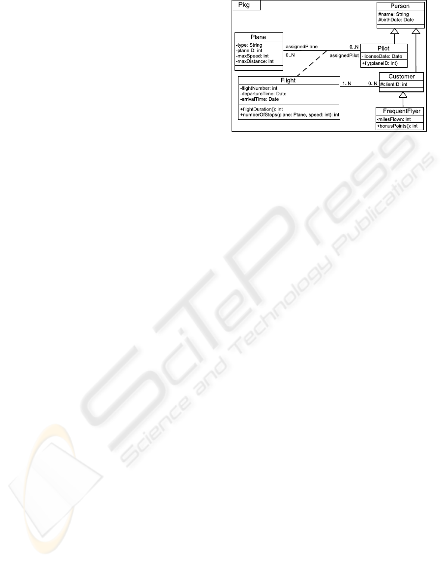
We present with an example, in Figure 1, the main
notations of a UML class diagram. A class (e.g. Pi-
lot) is drawn as a solid-outline rectangle. It contains
the name of the class in the top compartment, the at-
tributes (e.g. licenseDate) in the middle compartment,
and the operations (e.g. fly) in the bottom compart-
ment. This operation has one parameter, which is an
instance of the class Plane. The operation bonusPoints
of the class FrequentFlyer returns a data type int. The
generalization relation is represented by an arrowed
line drawn from the specialized class to the general
class. Then, the class Pilot has for generalization the
Person class, and the Person class has for subclasses
the classes Pilot, Customer and indirectly FrequentFlyer.
An association between the classes Pilot and Plane is
defined by the central Flight association class and by
the properties present at the ends of the association,
like the multiplicity 0..N. The association class, which
is a kind of class, is shown as a class symbol linked
by a dashed line to a line symbol of association. The
association between the classes Flight and Customer is
Figure 1: Example of a UML class diagram.
a more simple link that not explicitly needs an associ-
ation class.
2.2 Logical Form
We specify some terms that are used in this paper. We
consider a UML class diagram as a finite set of UML
notations. We call a UML notation a pair (concept,
element), where concept is one of the symbols that
constitute the UML class diagram language, and ele-
ment is an instance of this concept. For example, in
Figure 1 Plane is an element of the concept ‘class’.
We divide concepts in three sets: the set of entities,
the set of relations and the set of properties. An en-
tity is used to refer to general concepts such as: class,
attribute, operation, etc. A relation is either a general-
ization or an association between classes. A property
provides more precisely a meaning, like visibility or
multiplicity.
We recall that in a class diagram an element may
be described by some others. Then, these elements
are enclosed into it. For instance, a class is described
by its attributes and its operations. The entity that
encloses the others is the context of them.
Definition 1 (Logical Form). The Logical Form Φ
D
of a UML class diagram D is a FOL formula of con-
junction of predicates. A predicate in Φ
D
represents a
concept of the UML class diagram language. A con-
stant in Φ
D
refers to an element of D. Φ is obtained
according to Definitions 2 to 6.
In a UML class diagram some properties of ele-
ments are implicit. For instance, if nothing is spec-
ified, a class is by default not abstract. Please no-
tice that we explicitly express all implicit information
from a class diagram into its LF.
ICAART 2009 - International Conference on Agents and Artificial Intelligence
180

Figure 2: Set of entities.
2.2.1 Entities in Class Diagram
Definition 2 (LF of Entities). Let D be a UML class
diagram. A UML notation (E, e) of D, where e is an
instance of an entity E, is represented in Φ
D
by a bi-
nary predicate E. The first term of E is a constant,
called the context of e, and the second term is a con-
stant, called the identifier of e.
The entity predicates are partially ordered by a
kind-of relation, denoted by ≺ (Figure 2).
Example: The LF of the class Pilot is Φ
1
=
package(⊤, Pkg) ∧ class(Pkg, Pkg.Pilot) ∧
attribute(Pkg.Pilot, Pkg.Pilot.licenseDate) ∧
operation(Pkg.Pilot, Pkg.Pilot.fly) ∧ parame-
ter(Pkg.Pilot.fly, Pkg.Pilot.fly.planeID). The pred-
icates class, attribute, operation and parameter
represents some entities. Φ
1
indicates that Pilot, with
the single identifier Pkg.Pilot, is a class, licenseDate
is an attribute, fly is an operation, and planeID is a
parameter of fly. All of these elements are defined
in package Pkg. Remember that each element is
enclosed in a context, then the context of Pilot is Pkg,
the one of both licenseDate and fly is Pilot and the one
of planeID is fly.
First, note that the more general context is repre-
sented by the constant ⊤. Second, note that each ele-
ment is identified by a constant: for visibility reasons,
in our example an identifier is the element’s name pre-
fixed by its full context (but identifiers may be num-
bers as id
1
, id
2
, etc.). Third, Φ
1
will be completed in
Section 2.2.3 with some properties of these entities.
2.2.2 Relations in Class Diagram
There are two kinds of relations between classes: gen-
eralization and association.
Definition 3 (LF of Generalization). Let D be
a UML class diagram with notations (class,C
1
),
(class,C
2
) and (generalization link,g), such as g links
the more general class C
1
and the more specific C
2
.
The notation (generalization link,g) is represented in
Φ
D
by a ternary predicate generalization, where the
first term is the context of g, the second term is the
identifier of C
1
and the third term is the identifier of
C
2
.
Example: Descendants of Person are defined by Φ
2
=
generalization(Pkg, Pkg.Person, Pkg.Pilot) ∧ gener-
alization(Pkg, Pkg.Person, Pkg.Customer) ∧ general-
ization(Pkg, Pkg.Customer, Pkg.FrequentFlyer).
We have always chosen to represent a UML asso-
ciation relation as its most complete form, i.e. by us-
ing an association class. Then, each association from
a class diagram can be expended to an association that
is centralized by an association class.
Definition 4 (LF of Association). Let D be
a UML class diagram with notations (class,C
1
),
(class,C
2
), (association class,A), (role name,r
1
) and
(role name,r
2
) such as: C
1
and C
2
are linked together
through A; r
1
and r
2
are the two ends of A and are
respectively combined with C
1
and C
2
. An element
r
i
is an entity represented in Φ
D
by a binary predi-
cate role. A role r
i
and a class C
i
are combined in
Φ
D
by using a ternary predicate assoEnd, where the
first term is the context of A, the second is the identi-
fier of C
i
and the third is the identifier of r
i
. Then, a
role r
i
and A are linked in Φ
D
by a ternary predicate
association, where the first term is the context of A,
the second is the identifier of A and the third is the
identifier of r
i
.
Example: Association between Pilot and Plane:
Φ
3
= assoClass(Pkg, Pkg.Flight) ∧ role(Pkg,
Pkg.assignedPilot) ∧ role(Pkg, Pkg.assignedPlane)
∧ assoEnd(Pkg, Pkg.Pilot, Pkg.assignedPilot) ∧ as-
soEnd(Pkg, Pkg.Plane, Pkg.assignedPlane) ∧ asso-
ciation(Pkg, Pkg.Flight, Pkg.assignedPilot) ∧ asso-
ciation(Pkg, Pkg.Flight, Pkg.assignedPlane). The
constants Pkg.assignedPilot and Pkg.assignedPlane
identify the two ends of the association, which is cen-
tralized by the association class Flight.
Please first remark that the Definition 4 can be eas-
ily extended for n-ary associations (n≥ 2). Second,
note that Φ
3
will be completed in Section 2.2.3 with
properties.
2.2.3 Properties of Elements
Definition 5 (LF of Properties’ Elements). Let D be
a UML class diagram with a notation (P, (a,v)), where
the value for property P that is applied to the entity
2
or relation a is v. Notation (P, (a,v)) is represented
in Φ
D
by a ternary predicate P, where the first term
is the context of a, the second term is the identifier of
a and the third term is the identifier of the notation
(propVal,v) in the same context.
The property predicates are partially ordered by a
kind-of relation, denoted by ≺, whose greatest predi-
cate is property (Figure 3).
2
except propVal of course
A USEFUL LOGICAL SEMANTICS OF UML FOR QUERYING AND CHECKING UML CLASS DIAGRAM
181

Figure 3: Set of properties.
Please observe that named is a property that makes
the link between an identifier of an entity and its real
name in the class diagram.
Example: The example of the LF Φ
1
should now
be completed: Φ
′
1
= Φ
1
∧ ... ∧ named(Pkg,
Pkg.Pilot, Pilot) ∧ propVal(Pkg, Pilot) ∧ ... ∧
visibility(Pkg.Pilot, Pkg.Pilot.licenseDate, private) ∧
propVal(Pkg.Pilot, private) ∧ multiplicity(Pkg.Pilot,
Pkg.Pilot.licenseDate, 1-1) ∧ propVal(Pkg.Pilot, 1-
1) ∧ ...∧ rank(Pkg.Pilot.fly, Pkg.Pilot.fly.planeID,
#1) ∧ propVal(Pkg.Pilot.fly, #1). This completed
LF expresses also the fact the private attribute li-
censeDate has a multiplicity of 1-1 and it expresses
that the parameter planeID is the first parameter of
the operation fly. In the same way, Φ
′
3
= Φ
3
∧ named(Pkg,Pkg.assignedPlane,assignedPlane) ∧
propVal(Pkg, assignedPlane) ∧ ... ∧ multiplicity(Pkg,
Pkg.assignedPilot, multiplicity.0-N) ∧ propVal(Pkg,
0-N).
Definition 6 (Partial Ordering in Set of Concepts).
A FOL formula Φ
UML
to the set of UML concepts is
assigned. It corresponds to the interpretation of the
partial orderings of set of entities (Figure 2) and set
of properties (Figure 3). For all predicates p
1
and p
2
such as p
2
≺ p
1
, the formula ∀x
1
. . . x
n
(p
2
(x
1
. . . x
n
) →
p
1
(x
1
. . . x
n
)) is assigned, where n = 2 for entity pred-
icates and n = 3 for property predicates.
In Figure 2 or 3 the order between two concepts is
represented by a link between themselves such as the
more general concept is above the more specific con-
cept. For instance, the ordering assoClass ≺ class in
Figure 2 where class is the more general entity means
that, in a given context an association class is also a
class: ∀c,x assoClass(c,x) → class(c,x).
3 EXTENDING UML TO QUERY
AND TO CHECK CLASS
DIAGRAM
In addition to UML as a model for representing
knowledge, we propose a way for querying and
checking knowledge. Queries are used to find some
elements, and constraints to check some other. We in-
dicate in this section how to query and check UML
class diagram. Two new visual notations are intro-
duced into the UML model: variables and coloration.
3.1 Variables and Mappings
Definition 7 (Extended UML Class Diagram). Let
D be a UML class diagram. A variable x of D is de-
noted by the symbol
$
x. An entity notation (E,
$
x) of D
is represented in Φ
D
as it is defined in Proposition 1;
but the second term of predicate E is x. All variables
are existentially quantified in Φ
D
.
We call an extended UML class diagram a UML
class diagram that may have variables.
Asking for the existence of a mapping from an ex-
tended class diagram Q to a class diagram D can be
seen as a search such as all information contained in
Q is also contained in D.
Definition 8 (Mapping). Let Q be an extended UML
class diagram and D a UML class diagram.
A subset D
′
of D is called a mapping from Q to D
if Φ
UML
, Φ
D
′
Φ
Q
and ∀ D
′′
⊂ D
′
, Φ
UML
, Φ
D
′′
2 Φ
Q
.
3.2 Querying UML Class Diagram
Definition 9 (Result of a UML Query). A UML
query is an extended UML class diagram. Let D be
a UML class diagram and Q a UML query. The result
of the query Q to D is the set of mappings from Q to
D.
In a general way, a designer is interested in the
correspondencebetween each variable from Q and the
identifiers of instances of entities in a subset of D ac-
cording to a given mapping from Q to D.
Example: The LF of the query (Figure 4) is Φ
Q
= ∃p,c,x,y,z class(p,c) ∧ named(p,c,Person) ∧ prop-
Val(p,Person) ∧ class(p,x) ∧ generalization(p,c,x)
∧ operation(x,y) ∧ visibility(x,y,public) ∧ prop-
Val(x,public) ∧ parameter(y,z) ∧ ofType(y,z,int) ∧
primType(y,int). This query expresses the fact that “In
a package, does a class named by the value Person has
a subclass that has an operation with public visibility
and with one parameter of type called int?”. The re-
sult of this query to the class diagram of Figure 1 is
presented on the right side in Figure 4. The designer
can deduce that the intended class is Pilot with the op-
eration fly that has the parameter planeID.
Theorem 1. Let D be a UML class diagram and Q
an extended UML class diagram. M is the result of
query Q to D iff (1) ∀M ∈ M Φ
UML
, Φ
M
Φ
Q
; and
(2) ∀M ∈ M, ∄N ⊂ M such as Φ
UML
, Φ
N
Φ
Q
.
Proof. Let S be the set of subset of D. (⇒) Let M the
result of Q to D. Let D
′
a mapping from Q to D. (1)
ICAART 2009 - International Conference on Agents and Artificial Intelligence
182
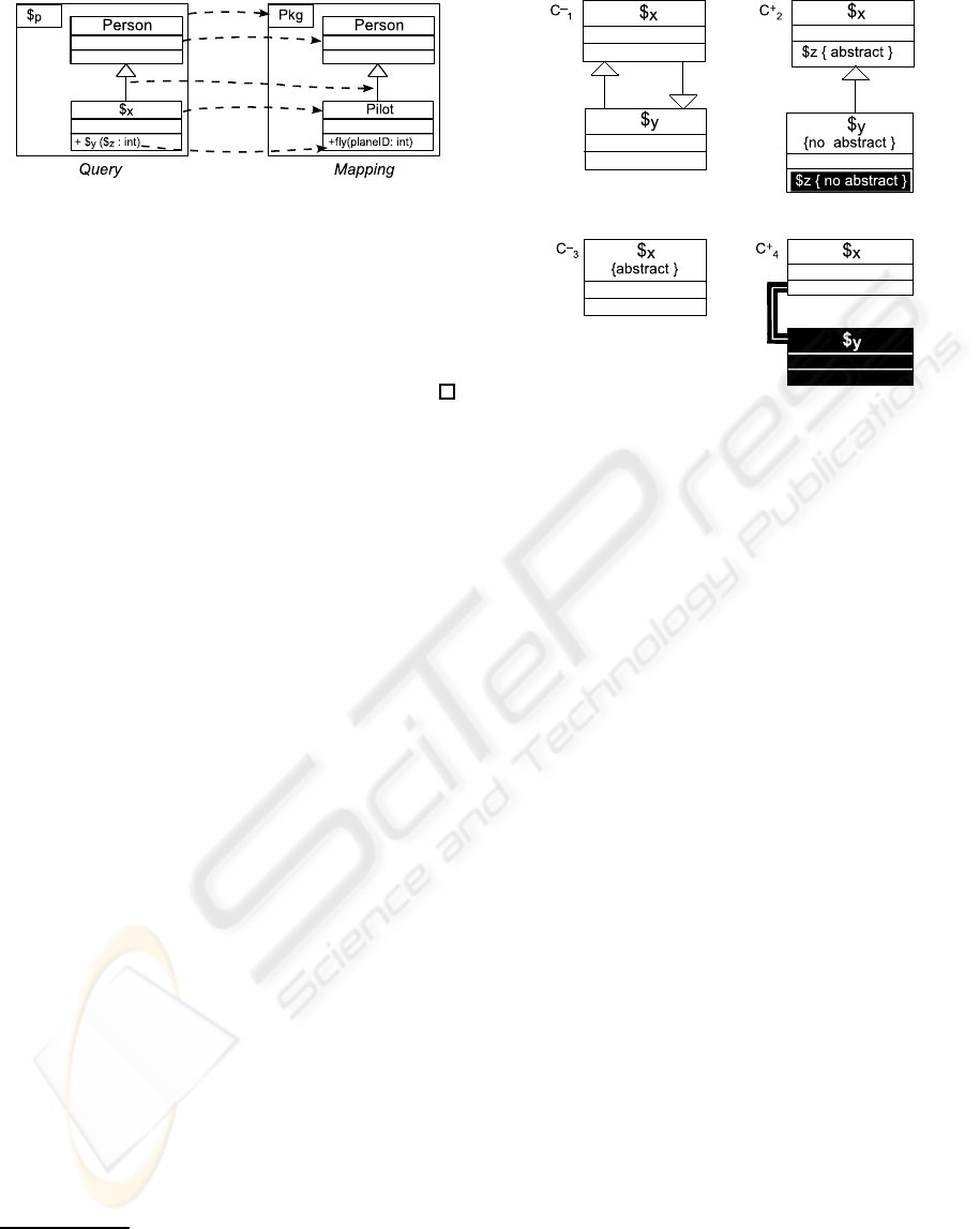
Figure 4: A UML query and a mapping.
Then, D
′
∈ M and Φ
UML
, Φ
D
′
Φ
Q
(by hypothesis).
(2) Let D
′′
∈ S where D
′′
⊂ D
′
, then Φ
UML
, Φ
D
′′
2 Φ
Q
(by hypothesis).
(⇐) Let M ∈ S where Φ
UML
, Φ
M
Φ
Q
and ∀N ∈ S
where N ⊂ M, Φ
UML
, Φ
N
2 Φ
Q
, then ∄N
′
∈ S where
N
′
⊂ M, Φ
UML
, Φ
N
′
Φ
Q
, so M ∈ M.
3.3 Checking UML Class Diagram
A class diagram is valid with respect to a set of con-
straints if it verifies each constraint. A constraint is
either negative or positive.
A negative constraint expresses an extended class
diagram that must not be found in the class diagram to
validate. A positive constraint expresses a specifica-
tion like “if A, then obligation B”. Coloration is used
to distinguish premise from obligation.
Definition 10 (UML Negative Constraint). A UML
negative constraint is an extended UML class dia-
gram.
Definition 11 (UML Positive Constraint). Col-
oration is an application that associates a color 0 or
1 with each notation of an extended UML class di-
agram. A UML positive constraint C
+
is a colored
extended UML class diagram, which is divided into
two parts: a premise and an obligation. The premise
is the subset with 0-colored notations (white back-
ground) and obligation the subset with 1-colored no-
tations (black background).
Without considering coloration: C
+
p
is called the
premise of C
+
, Φ
C
+
p
its LF, and Φ
C
+ the LF of C
+
.
Notice that Φ
C
+ is not the logical semantics (due to
coloration) of C
+ 3
.
Example: Figure 5 shows two negative constraints
C
−
1
and C
−
3
, and two positive constraints C
+
2
and C
+
4
.
C
−
1
expresses the following prohibition: “a class X
can be a subclass of a class Y, which is a subclass of
3
Let Ψ
p
be defined as Φ
C
+
p
without existential quanti-
fiers, and Ψ
o
as the LF of the obligation without existential
quantifiers. Let x
1
, .., x
n
be the variables of Ψ
p
and y
1
, .., y
m
the variables of Ψ
o
that are not in Ψ
p
. The logical semantics
of C
+
is as ∀x
1
. . . ∀x
n
Ψ
p
→ ∃y
1
. . . ∃y
m
Ψ
o
.
Figure 5: UML positive and negative constraints.
X”. In other words, this constraint checks that “there
is no simple inheritance cycle”. C
+
2
expresses the fol-
lowing obligation: “if a class X has an abstract opera-
tion z, for each subclass Y of X that is non-abstract,
z must necessarily be overwritten as a non-abstract
operation”. C
−
3
expresses that “abstract classes” are
prohibited. C
+
4
expresses that “each class has to be
associated with another class”.
Please observe that we consider constraints to be
divided into two groups: object oriented constraints
and specific constraints. The first group refers to con-
straints for verifying if class diagram respects the ob-
ject oriented specifications. The second group may
express any requirement in addition to the object ori-
ented specifications that the designer needs according
to corporate project specifications. C
−
1
and C
+
2
are
object oriented constraints, and C
−
3
and C
+
4
specific
constraints.
Definition 12 (Verification of UML Constraint).
Let D be a UML class diagram, C
−
a UML negative
constraint, C
+
a UML positive constraint.
D verifies C
−
if there is no mapping from C
−
to D.
D verifies C
+
if for each mapping M from the
premise of C
+
to D, there is a mapping M
′
from C
+
to
D such as M ⊆ M
′
.
Example: The class diagram in Figure 1 is valid ac-
cording to constraints C
−
1
, C
+
2
and C
−
3
, but it is not
valid according to C
+
4
. Indeed, there is a mapping
from the premise of C
+
4
to the class Person, but there
is no mapping from (whole) C
+
4
to the class diagram
concerning Person (no association).
Theorem 2. Let D be a UML class diagram and
C
−
a UML negative constraint. D verifies C
−
iff
Φ
UML
, Φ
D
2 Φ
C
− .
A USEFUL LOGICAL SEMANTICS OF UML FOR QUERYING AND CHECKING UML CLASS DIAGRAM
183

Proof. (⇒) Let S be the set of subset of D. There
is no mapping from C
−
to D, then ∄D
′
∈ S where
D
′
⊆ D such as Φ
UML
, Φ
D
′
Φ
C
− (by hypothesis).
So, Φ
UML
, Φ
D
2 Φ
C
− , because D ⊆ D.
(⇐) Immediate from hypothesis.
Theorem 3. Let D be a UML class diagram, C
+
a
UML positive constraint. D verifies C
+
iff for all
substitution σ of all variables of C
+
p
, if Φ
UML
, Φ
D
σ(Φ
C
+
p
), then there is a substitution σ
′
of all variables
of C
+
where σ ⊆ σ
′
and Φ
UML
, Φ
D
σ
′
(Φ
C
+ ).
Proof. (⇒) Let M
p
be the set of mapping from C
+
p
to D; and M
c
the set of mapping from C
+
to D. Let
M ∈ M
p
, then there is a substitution σ
1
of all variables
of C
+
p
such as Φ
UML
, Φ
D
σ
1
(Φ
C
+
p
) (by hypothesis)
and because there is no variable into Φ
D
. ∃M
′
∈ M
c
,
then there is a substitution σ
′
1
of all variables of C
+
such as Φ
UML
, Φ
D
σ
′
1
(Φ
C
+ ) and σ
1
⊆ σ
′
1
(because
M ⊆ M
′
).
(⇐) Let S be the set of subset of D. Let σ
1
a sub-
stitution of all variables of C
+
p
where Φ
UML
, Φ
D
σ
1
(Φ
C
+
p
) (A), then there is a substitution σ
′
1
of all
variables of C
+
where Φ
UML
, Φ
D
σ
′
1
(Φ
C
+
) (B).
By (A), ∃D
′
∈ S, ∀D
′′
∈ S where D
′′
⊆ D
′
such as
Φ
UML
, Φ
D
′
σ
1
(Φ
C
+
p
) and Φ
UML
, Φ
D
′′
2 σ
1
(Φ
C
+
p
).
By (B) and σ
1
⊆ σ
′
1
(by hypothesis), Φ
UML
, Φ
D
σ
′
1
(Φ
C
+
p
) and so Φ
UML
, Φ
D
σ
1
(Φ
C
+
p
) (C). By (B)
and (C), ∃B
′
∈ S with D
′
⊆ B
′
and ∀B
′′
∈ S where B
′′
⊆
B
′
such as Φ
UML
, Φ
B
′
σ
′
1
(Φ
C
+ ) and Φ
UML
, Φ
B
′′
2
σ
′
1
(Φ
C
+ ).
4 CONCLUSION
We have proposed an original logical semantics to
UML class diagram and an extention of UML to ex-
press queries and (positive and negative) constraints.
Our approch is useful to query and to check UML
class diagram for respectively answering queries and
satisfying constraints that both can be modelled in ex-
tended UML as well. Notice that the definition in this
article of constraints (using bicoloration) is inspired
by constraints of (Chein and Mugnier, 1997) from
the model of conceptual graphs (Chein and Mugnier,
1992; Wermelinger, ). So, it could be interesting to
translate logical form of UML class diagram into this
model, and then use its reasoning operation (called
projection) both to answer queries and to test con-
straints.
REFERENCES
Akkerman, H., Anjewierden, A., Hoog, R. D., Shad-
bolt, N., de Welde, W. V., and Wielenga, B. (1999).
Knowledge engineering and management: the Com-
monKads methodology. MIT Press.
Beckert, B., Keller, U., and Schmitt, P. H. (2002). Translat-
ing the Object Constraint Language into First-order
Predicate Logic. In Proc.of VERIFY, Workshop at
FLoC’02.
Berardi, D., Calvanese, D., and De Giacomo, G. (2005).
Reasoning on UML class diagrams. Artificial Intelli-
gence, 168(1):70–118.
Booch, G., Jacobson, C., and Rumbaugh, J. (1998). The
Unified Modeling Language - a reference manual. Ad-
dison Wesley.
Chein, M. and Mugnier, M.-L. (1992). Conceptual Graphs:
Fundamental Notions. Revue d’intelligence artifi-
cielle, 6(4):365–406.
Chein, M. and Mugnier, M.-L. (1997). Positive nested con-
ceptual graphs. In Proc. of ICCS’97, volume 1257 of
LNAI, pages 95–109. Springer.
OMG. UML 2.0 Object Constraint Language Specification.
http://www.omg.org/docs/ptc/03-10-14.
OMG. Unified Modeling Language Specification:
Infrastructure, v2.0. http://www.omg.org/cgi-
bin/doc?ptc/04-10-14.
OMG. Unified Modeling Language Specification:
Superstructure, v2.0. http://www.omg.org/cgi-
bin/doc?formal/05-07-04.
Rosati, R. (2007). The Limits of Querying Ontologies.
In Proceedings of 11th International Conference in
Database Theory (ICDT’07), volume 4353 of Lecture
Notes in Computer Science (LNCS), pages 164–178.
Springer.
Soon-Kyeong, K. and Carrington, D. (2000). A Formal
Mapping between UML Models and Object-Z Spec-
ifications. In Proc. of ZB ’00, volume 1878 of LNCS,
pages 2–21. Springer.
Wermelinger, M. Conceptual Graphs and First-Order Logic.
pages 323–337.
ICAART 2009 - International Conference on Agents and Artificial Intelligence
184
