
FORMAL SPECIFICATION AND VERIFICATION OF
MULTI-AGENT ROBOTICS SOFTWARE SYSTEMS
A Case Study
Nadeem Akhtar, Yann Le Guyadec and Flavio Oquendo
Universite Europeenne de Bretagne, UBS
VALORIA Computer Science Laboratory, France
Keywords:
Multi-Agent Systems, Agent Models and Architecture, Gaia multi-agent methodology, Formal methods, For-
mal verification, Finite State Process (FSP), Labelled Transition System (LTS), Labelled Transition System
Analyzer (LTSA), Safety property, Liveness property, Deadlock.
Abstract:
One of the most challenging task in software specifications engineering for robotics multi-agent systems is
to ensure correctness. As these systems have high concurrency, often have dynamic and distributed environ-
ments, the formal specification and verification of these systems along with step-wise refinement from abstract
to concrete concepts play major role in system correctness. Our objectives are the formal specification, anal-
ysis with respect to functional as well as non-functional properties by step-wise refinement from abstract to
concrete specifications and then formal verification of these specifications. Multi-agent robotics systems are
concurrent systems with processes working in parallel with synchronization between them. We have worked
on Gaia multi-agent method along with finite state process based finite automata techniques and as a result we
have defined the formal specifications of our system, checked the correctness and verified all possible flow of
concurrent executions of these specifications. Our contribution consists in transforming Gaia organizational
abstractions into executable FSP specifications that can be verified using LTS. We have considered a case
study of our multi-agent robotics system to exemplify formal specifications and verification.
1 INTRODUCTION
One of the most challenging tasks in software engi-
neering for multi-agent system is to ensure continu-
ous correctness, especially as software systems are in-
creasingly used in dynamic and often distributed envi-
ronments, to support the formal specification of soft-
ware systems whose architecture can change, to sup-
port their analysis with respect to functional as well
non-functional properties, to support their design by
step-wise refinement from abstract to concrete speci-
fications and full code generation, as well as their sub-
sequent evolution.
An agent as a computer system situated in some
environment, capable of autonomous actions in this
environment in order to meet its design objectives
(Wooldridge and Jennings, 1995). Multiple agents
are necessary to solve a problem, especially when
the problem involves distributed data, knowledge, or
control. A multi-agent system is a collection of sev-
eral interacting agents in which each agent has incom-
plete information or capabilities for solving the prob-
lem (Jennings et al., 1998). These are complex sys-
tems and their specifications involve many levels of
abstractions.
While considering multi-agent methods we have
selected Gaia (Wooldridge et al., 2000)(Zambonelli
et al., 2003) as it is based on computation organiza-
tion with various interacting roles. It is both general,
in that it is applicable to a wide range of multi-agent
systems, and comprehensive, in that it deals with both
the macro-level (societal) and the micro-level (agent)
aspects of systems. It has a concrete syntax to ex-
press properties, and it is suitable to model behav-
iors. Gaia multi-agent method is the principal can-
didate for the specifications whereas Finite State Pro-
cess (FSP) with Labelled Transition System Analyzer
(LTSA)(Magee and Kramer, 2006) has been selected
for the verification of specifications as it is a formal
language specifically useful for specifying concurrent
behaviour and can generate finite automates by using
LTSA.
We have considered a case study consisting of
small multi-agent robotics software agents working
475
Akhtar N., Le Guyadec Y. and Oquendo F. (2009).
FORMAL SPECIFICATION AND VERIFICATION OF MULTI-AGENT ROBOTICS SOFTWARE SYSTEMS - A Case Study.
In Proceedings of the International Conference on Agents and Artificial Intelligence, pages 475-482
DOI: 10.5220/0001657904750482
Copyright
c
SciTePress
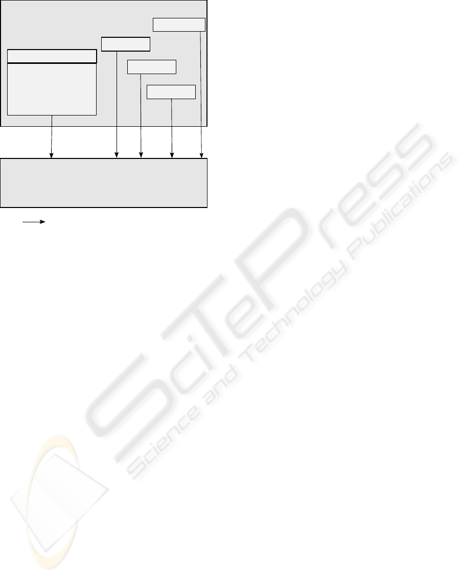
Role model
Interaction model
- Protocol & Activities
- Permissions
- Responsibilities
Liveness property & Safety property
FSP (Finite State Process) based LTSA (Labelled Transition System Analyser)
- checks safety
- checks liveness
- checks progress (number of transitions, terminal set of states)
- checks deadlock & potential deadlocks
Gaia method
( Specification definition )
Agent model
Acquantances
model
represents the transformation from Gaia to FSP
where
Services model
Figure 1: Global view of the method.
in a closed environment, formal methods are used i.e.
Gaia specifications and then its FSP modeling for the
formal specification and verification of the system as
shown in figure-1.
In this article the main focus is on the formal spec-
ification and property-checking aspects of the system.
section-2 presents the problem statement, section-
3 the formal methods, section-4 the Gaia overview
section-5 FSP and LTS, section-6 case study, section-
7 lessons learned and conclusion.
2 PROBLEM STATEMENT
Multi-agent systems are specialized systems with
greater autonomy, complexity, abstraction and con-
currency and therefore we need specialized methods
and formal languages.
The objectives to have a formal foundation for
the languages and tools are: to improve understand-
ing of specifications, to enable rigorous analysis of
the system properties, to be as certain as possible that
the transformations and implementation are property-
preserving and error-free, to improve the quality of
the whole development process, and to provide a firm
foundation during the adaptation and evolution pro-
cess. There is a need of formal methods, techniques,
design tools and languages for specification defini-
tion, architecture description and definition of layers
of abstractions.
There are some existing multi-agent methods such
as Gaia and TROPOS (Giunchiglia et al., 2001) and
among these method we have found Gaia as the most
suitable one for our work as it recognizes the organi-
zational structure is a primary dimension for the de-
velopment of agent system and an appropriate choice
of it is needed to meet both functional and non-
functional requirements. Presently we have proposed
an architecture consisting of formal methods and lan-
guages for requirement definition, specification defi-
nition and formal verification.
It has been observed that there is a need of for-
mal verification for Gaia specifications of our system.
Here we start from Gaia for requirement definition
and specification definition, FSP for the formal ver-
ification by using LTSA and then a simulation imple-
mentation by using MRDS (Microsoft Robotics De-
veloper Studio) (Microsoft, 2007).
3 FORMAL METHODS
Formal methods are based on solid mathematical
foundations. Formal verification is the act of proving
or disproving the correctness of underlying system al-
gorithms with respect to certain formal specifications
using formal methods of mathematics.
Two main types of formal methods are available: al-
gebraic approaches and model-checking. Algebraic
approaches such as B (Abrial, 1996) describes a sys-
tem with axioms and then proves a property on the
specification as a theorem to be demonstrated from
these axioms. However theorem provers that are
required to elaborate the proof are difficult to use
and still require highly skilled and experience engi-
neers. In contrast, model-checking (Clarke et al.,
2000) (Brard et al., 2001) is the exhaustive investiga-
tion of a system state space. This technique is limited
by the combinatorial explosion and can mainly ad-
dress finite systems. However, recent symbolic tech-
niques scale up to more complex systems. Here by
complex we mean a system with a large number of
independent interacting components, with nonlinear
aggregate activity, with concurrency between compo-
nents and constant evolution. Thus, since formal veri-
fication techniques are getting more mature, our capa-
bility to build even more complex systems also grows
quickly.
Formal verification can achieve complete exhaustive
coverage of the system thus ensuring that undetected
failures in the behaviour are excluded. The goal is
to formally verify that each component is consistent
with the rest, agents are able to fulfill their commit-
ments. Correctness of an agent software system can
be proved by formalizing different components and
processes in the life-cycle. The case study is pre-
ICAART 2009 - International Conference on Agents and Artificial Intelligence
476
sented in section-6 with the formal correctness which
requires formal verification.
4 GAIA OVERVIEW
Gaia (Wooldridge et al., 2000) (Zambonelli et al.,
2003) clearly identifies the appropriate organizational
abstractions in a multi-agent system and details the
analysis and design of such systems. These orga-
nizational abstractions are necessary to design and
built complex systems. Gaia is not directly related
with particular modeling techniques and implemen-
tation issues. After the successful completion of the
design process, developers are provided with a well-
defined set of agent roles to manually implement and
instantiate, according to the defined agent and ser-
vices model.
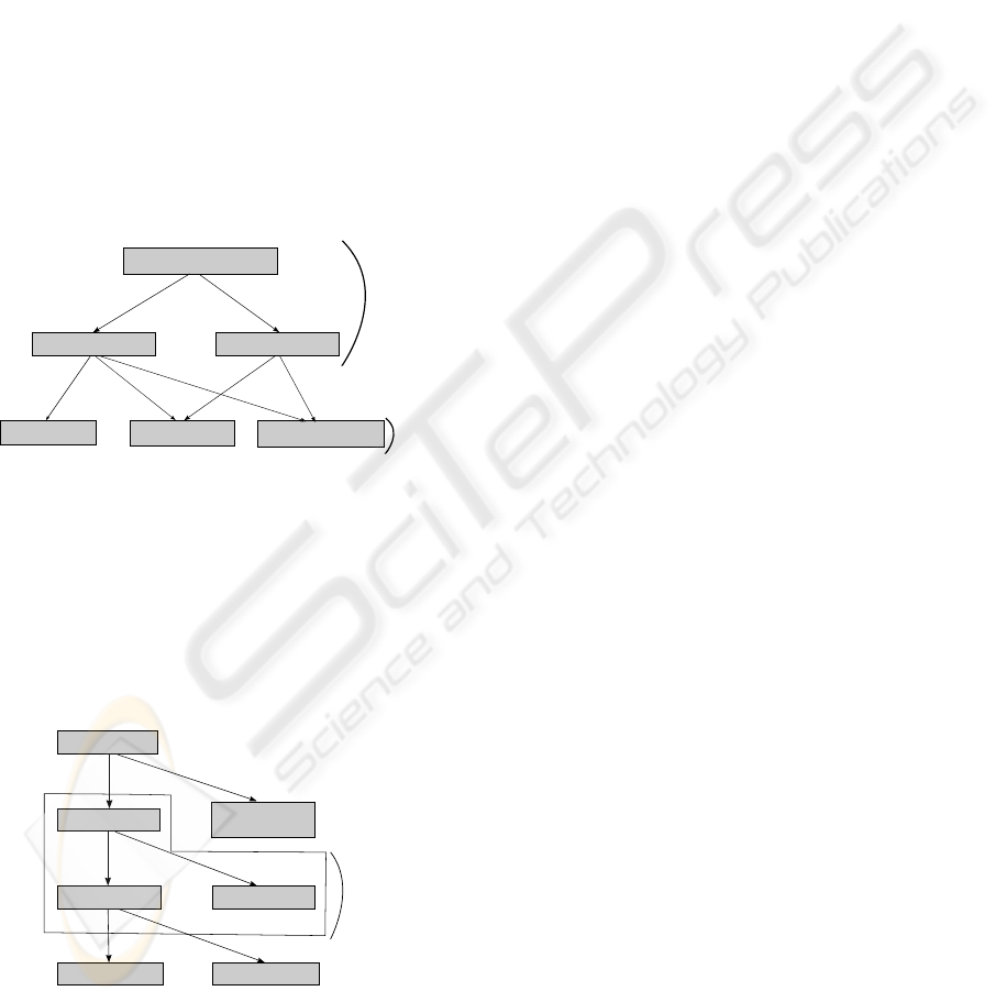
Specifications
Design
interaction model
agent model
services model
acquaintance model
Requirement definition
role model
Figure 2: Relationships between Gaia’s models.
As shown in figure-2 Gaia is divided into various
models i.e role, interaction, agent, services and ac-
quaintance models. Role model and interaction model
constitute the analysis phase that play the most im-
portant part and that can be extended by using for-
mal methods and techniques. Agent, services and ac-
quaintance model constitute the design phase.
system
roles
responsibilities
permissions
safety properties
liveness properties
interactions
(protocols)
roles model
Figure 3: Gaia roles, permissions and responsibilities
(safety and liveness properties).
The Gaia’s role model manages permissions and
responsibilities. permissions are classified into two
types internal and external. Internal permissions
are those resources or properties associated with
only the agent and don’t involve interaction with
the environment or another agent. permissions are
mainly aimed at
(i) identifying the resources that can legitimately be
used to carry out the role i.e what can be spent while
carrying out the role
(ii) In order to carry out a role, an agent will typically
have to access environmental resources and possibly
change.
Whereas responsibilities attributes determine the
expected behaviour of a role and the key attributes
associated with a role. They include the liveness
and safety properties that play important role for the
formal verification of the system.
The key phases of Gaia can be summarized as:
• The definition of the system’s organizational
structure in terms of its topology and control
regime. It involves considering: (i) organiza-
tional efficiency (ii) real-world organization and
(iii) need to enforce the organizational rules.
• Identify the roles in the system. They will
typically correspond to individual agents, either
within an organization of agents or acting inde-
pendently
output: a prototypical roles model, a list of the
key roles that occur in the system, each with an
informal description that is not elaborated.
• For each role, identify and document the associ-
ated protocols
output: an interaction model, which captures the
recurring patterns of role interactions.
• Using the interaction model (protocol definitions)
as a base to elaborate the roles model
output: a fully elaborated roles model, which doc-
uments the key roles occurring in the system, their
permissions and responsibilities, together with the
protocols and activities in which they participate.
• The completion of the role and interaction mod-
els based on the adopted organizational struc-
ture and involves separating whenever possible
the organizational-independent aspects from the
organizational-dependent ones. This demarcation
promotes a design-for-change perspective by sep-
arating the structure of the system from its goals.
Safety and Liveness Properties. Safety property is
an invariant which asserts that “nothing bad happens”,
that is an acceptable state of affairs is maintained.
Safety property P = {a1,a2..an} defines a deter-
ministic process that asserts that any trace including
FORMAL SPECIFICATION AND VERIFICATION OF MULTI-AGENT ROBOTICS SOFTWARE SYSTEMS - A Case
Study
477
actions in the alphabet of P, is accepted by P.
Liveness property asserts that “something good hap-
pens” that describe the states of system that an agent
must bring about given certain conditions. In the
Gaia’s role model liveness properties are specified via
liveness expressions which defines the potential ex-
ecution trajectories through the atomic components
(activities and interactions) associated with the role.
An activity corresponds to a unit of action that the
agent may perform, which does not involve interac-
tion with any other agent. Protocols, on the other
hand are activities that require interaction with other
agents.(Zambonelli et al., 2003)
Operator
Interpretation
x.y
x followed by y
x|y x or y occurs
x
∗
x occurs 0 or more times
x
+
x occurs 1 or more times
x
ω
x occurs indefinitely often
[x] x is optional
x||y x and y interleaved
Figure 4: Gaia operators for liveness expres-
sions(Zambonelli et al., 2003).
The most widely used formalism for specifying
liveness and safety properties is temporal logic, and
the use of such a formalism has been strongly advo-
cated for use in agent systems (Wooldridge, 2000).
5 FSP AND LTS OVERVIEW
FSP is a process algebra notation in the form of fi-
nite state processes used for the concise description of
component behaviour particularly for the concurrent
systems. It provides the means to formalize specifica-
tion of software components and architecture. Each
component consists of processes and each process has
finite number of states and is composed of one or
more actions. Because of its strong parallel constructs
it is used in particular for parallel and concurrent sys-
tems. There exists concurrency between elementary
calculatory activities for which there is a need to man-
age the interactions, communication and synchroniza-
tion between processes.
(Magee and Kramer, 2006) have proposed an ana-
lyzer LTSA i.e toolkit for LTS. A system in the LTSA
is modeled as a set of interacting finite state machines
along with their properties. LTSA performs compo-
sitional reachability analysis to exhaustively search
for violations of the desired properties. More for-
mally, each component of a specification is described
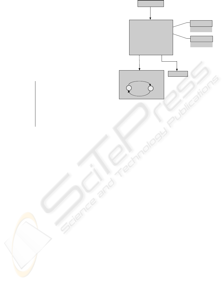
FSP specifications
LTS Analyzer
(uses FSP as input)
process (multiple actions)
parallelism & concurrency
synchronization
Safety property
Liveness property
checks
checks
Finite automates
(consisting of finite processes)
Animation
generates
0
1
Progress
Deadlock detection
generates
translate
Figure 5: FSP along with LTSA toolkit
as LTS, which have all the possible states a compo-
nent may reach and all the possible transitions it may
perform. However, explicit description of an LTS in
terms of its states, set of action labels and transition
relation is cumbersome for other than small systems.
As shown in figure-5 FSP specify the behaviour
of concurrent systems to the LTSA which in turn
generates finite automata based on Labelled Tran-
sition Systems and makes it possible to view the
graphical representation of the LTS corresponding
to FSP specifications. Therefore FSP is used to
formalize specification of software components
and Labelled Transition System is used to verify
system-level concurrency properties. As a result
we are able to obtain a concurrent system in which
there are processes working in parallel and there are
synchronizations between different processes.
Progress and Deadlock Detection. The regular
occurrence of some actions in a system execution
indicates that system behaviour progresses as desired
or expected. In the context of an infinite execution,
regularly means infinitely often i.e. a property that
asserts that an action is expected to occur infinitely
often in every infinite execution of the system, the
liveness properties of this type are progress.
progress P = {a1,a2..an} defines a
progress property P which asserts that in an infinite
execution of a target system, at least one of the
actions a1,a2..an will be executed infinitely often
(Giannakopoulou et al., 1999).
In systems with parallel processes deadlock refers
ICAART 2009 - International Conference on Agents and Artificial Intelligence
478
to a situation where two or more processes are un-
able to proceed because each is waiting for one of
the others to do something. In these systems one of
the major issues is the deadlock detection and pre-
vention to conceptualize a system that is deadlock
free. In LTS a system having two or more parallel
processes, each having shared actions i.e having ac-
tions between different processes being synchronized
by renaming there exists significant possibilities of
deadlock. Progress and deadlock are two terms that
are somewhat related if there is a deadlock in the sys-
tem than it results into a progress violation.
6 CASE STUDY: MULTI-AGENT
ROBOTICS TRANSPORT
SYSTEM
In this section we present our multi-agent robotic sys-
tem which is composed of transporting agents. Over-
all mission is to transport material from one store-
house to another. They move in their environment
which is static i.e the topology of the system does not
evolve at run time. There is a possibility of collision
between agents while transportation. Collision reso-
lution techniques are applied to avoid system dead-
lock.
6.1 Types of Agents
There are three types of agents
1- Carrier Agent: agent that transports material from
one storehouse to another one, it can be loaded or
unloaded and can move both forward and backward
direction. Each road section is marked by a sign
number and the carrier agent can read this number.
It also has a sensor to detect a collision with another
carrier.
2- Loader/ Unloader Agent: It receives/delivers
material from the storehouse, can detect if a carrier
is waiting (for loading or unloading) by reading the
presence sensor, it ensures that the carrier waiting
to be loaded is loaded and the carrier waiting to be
unloaded is unloaded.
3- Store-manager Agent: manages the material count
in the storehouse and transports the material between
the storehouse and the loader/unloader.
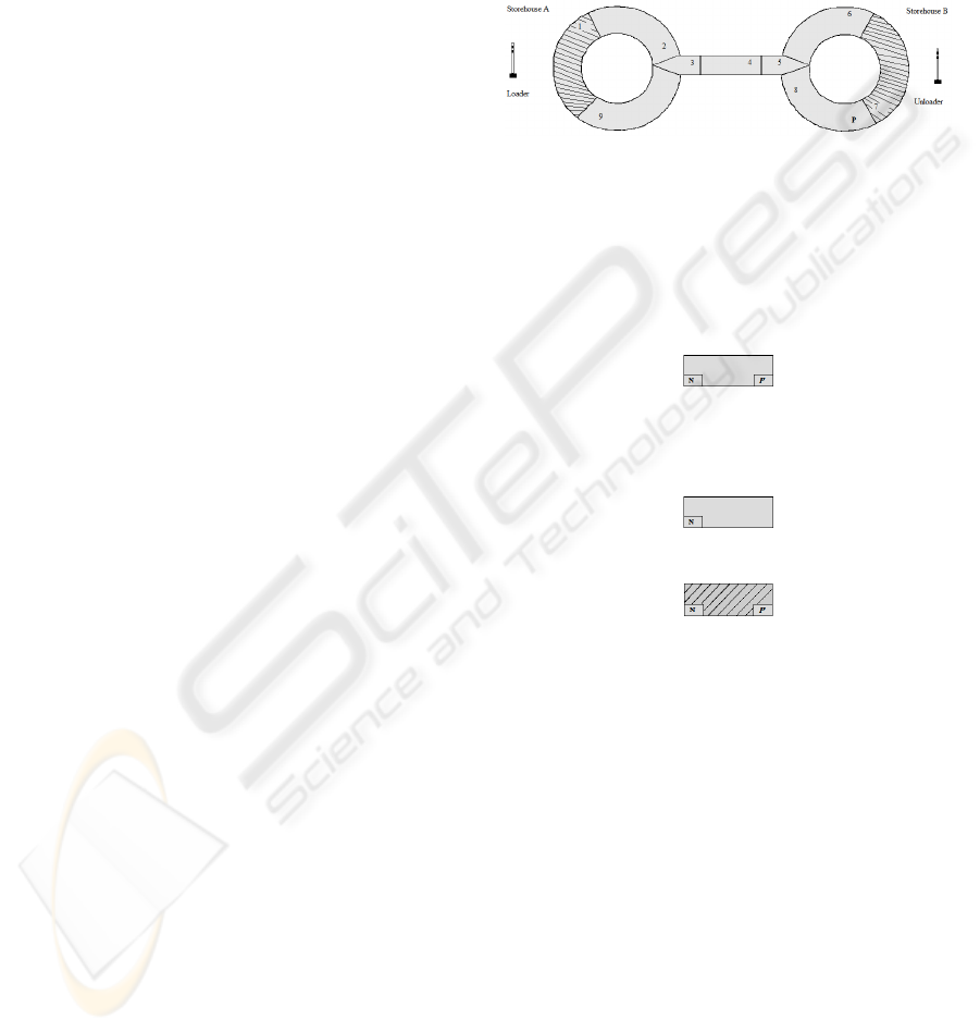
6.2 Environment
There is a road between storehouse-A and storehouse-
B which is composed of a sequence of interconnected
sections of fixed length as shown by figure-6. Each
road section has a numbered sign, which is readable
by carrier agents.
There are three types of road sections depending
upon the topology of the road. Each of the three
types of road sections have a unique numbered sign.
The road is single lane and there is a possibility of
collision between agents. There is a roundabout at
storehouse-A and storehouse-B.
a) where N is the unique numbered sign. P is the park-
ing Flag (TRUE or FALSE) i.e. the section can be
used as a parking
(b)
(c) road section present at the loader and unloader,
detects the presence of the carrier agents at the loader
and unloader
Figure 6: Environment with road partitions.
6.3 Scenario
In the case study we have used a particular road
topology consisting of nine road partitions as shown
in figure-6. Its a mini-route that can be presented here
in this paper with all its states. We have considered
the case in which initially storehouse A is full and
storehouse B is empty. The main task of the carrier
is to transport the material from storehouse A to
storehouse B until the storehouse A is empty. Loader
at the storehouse A loads the carrier with material
and the Unloader at the storehouse B unloads the car-
rier. The store-manager keeps a count of material in
each storehouse. In this case the environment is static.
FORMAL SPECIFICATION AND VERIFICATION OF MULTI-AGENT ROBOTICS SOFTWARE SYSTEMS - A Case
Study
479

At the central section (3,4,5) there is a possibil-
ity of collision between carrier agents coming from
the opposite directions. Priority is given to the loaded
carriers i.e if there is a collision between a loaded and
an empty carrier than the empty carrier moves back
and waits at the parking region of the route until the
loaded carrier passes and unloads. The parking region
as shown in the figure consists of the road partition 8.
6.4 Gaia Development and
Transformation
The major part of the work is to take the Gaia spec-
ifications and then use them in a way that they can
be verified by using FSP language. Gaia methodol-
ogy as described in section-4 consists of a number of
models, we may be looking into only the roles model
and interaction model which constitutes the analysis
phase of Gaia.
6.4.1 Role Model
The role of an agent defines what it is expected to do
in the organization, both in concert with other agents
and in respect of the organization itself.
Role Schema: Move full
Description:
This role involves transferring a loaded carrier from the
storehouse A to storehouse B.
Protocols and Activities:
ReadSign, MovetoNext, CollisionSensorTrue,
CarrierWait,ReadUnloadSign, WaitforUnloading,
UnloadCarrier
Permissions:
reads:
sign number (external)
collision sensor (internal)
changes:
position (internal)
Responsibilities:
Liveness:
Move full = Move.(ReadUnloadSign.WaitforUnloading.
UnloadCarrier)
Move = (ReadSign.MovetoNext)+
| (CollisionSensorTrue.Wait).
Wait = (CarrierWait)+
Safety:
(SignNumber ∈
{
2, .., 6
}
⇒ is.loaded)
∧
(SignNumber ∈
{
2, .., 6
}
∧ next position = SignNumber+1 ⇒ is.loaded)
Figure 7: Move full role of Gaia Role model.
Often an agent’s role is simply defined in terms of
the specific task that it has to accomplish in the con-
text of the overall organization. Organizational role
models precisely describe all the roles that constitute
the computational organization. They do this in terms
of their functionalities, activities, responsibilities as
well as in terms of their interaction protocols and pat-
terns. In the role model the liveness and safety ex-
pressions play important role for system verification.
Here in this paper due to space constraints we pre-
sented one of the roles the Move full role of our sys-
tem i.e. role of a loaded carrier agent moving from
Storehouse-A to Storehouse-B.
Here activities (underlined) are ReadSign,
MovetoNext, CollisionSensorTrue, CarrierWait
and ReadUnloadSign. And there are two proto-
cols WaitforUnloading and UnloadCarrier
WaitforUnloading: when a loaded carrier read the
unload sign i.e. it reaches the unload road partition, it
stops there and waits until it is unloaded.
Consider the Liveness property of the Move full
role. It shows all the activities and protocols that
make up the role. The carrier has two choices, first
it can read sign and move to the next road partition,
second it detects the collision sensor then it waits,
at the end it reads the unload sign i.e at the road
partition in front of the unloader, and in this case the
carrier stops and waits for being unloaded, so now
its no more a loaded carrier and is no more part of
the Move full role. Safety property is an invariant
that is either true or false, here the safety property
verifies that when the carrier agent is in one of the
road partitions (2,3,4,5,6) then it is loaded and the
next position is equal to the previous position plus 1.
6.4.2 Interaction Model
There are dependencies and relationships between
the various roles in a multi-agent organization which
are the set of protocol definitions, one for each type
of inter-role interaction. Here table-1 shows the
protocol definitions related to Move full role.
Table 1: Protocol definitions related to Move full role.
WaitForUnloading
Carrier Loader
Wait until the carrier is being
unloaded with goods
WaitForLoading
Carrier Unloader
Wait until the carrier is
being loaded
WaitForStoremanager
StoreManager Loader | Unloader
Loader waits until the
storemanager transfers material to loader
LoadCarrier
Loader Carrier
Loads the carrier with
material
UnloadCarrier
Unloader Carrier
Unload the material from the carrier
ICAART 2009 - International Conference on Agents and Artificial Intelligence
480
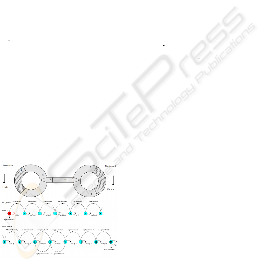
6.5 FSP Specifications of the System
We formally defined our system using FSP, verified
all the possible flow of executions. In our system the
road is the environment and each carrier has its par-
ticular route. The route is the path taken by the car-
rier agents on the road to transfer the material from
one storehouse to another. Here shown in figure-8 is
the FSP specifications for the route. With the help
of the LTSA this code generates a finite automate of
the route. In short, we have generated an automate of
the route with all the possible executions that can take
place on this route.
Carrier moves in a clockwise direction on this route.
Here the route has been classified in two types the
FULL ROUTE path taken by full carriers and the
EMPTY ROUTE path taken by empty carriers.
// mini route: all possible choices for empty & full carriers
const TRUE = 1
const Max = 9
range R = 1..Max
ROUTE = FULL_ROUTE[1],
FULL_ROUTE[v:R]=
( readSign[v] -> FULL_ROUTE[v]
| when (v>=1 & v<=6) full.movetonext -> FULL_ROUTE[v+1]
| when (v==7) full.waitforUnloading -> EMPTY_ROUTE[7]
),
EMPTY_ROUTE[v:R]=
( readSign[v] -> EMPTY_ROUTE[v]
| when (v==7) empty.movetonext -> EMPTY_ROUTE[v+1]
| when (v==8) empty.movetonext -> EMPTY_ROUTE[5]
| when (v==5) empty.movetonext -> EMPTY_ROUTE[v-1]
| when (v==4) empty.movetonext -> EMPTY_ROUTE[v-1]
| when (v==3) empty.movetonext -> EMPTY_ROUTE[9]
| when (v==9) empty.movetonext -> EMPTY_ROUTE[1]
| when (v==4) empty.movetoPrevious -> EMPTY_ROUTE[v+1]
| when (v==5) empty.movetoPrevious -> EMPTY_ROUTE[8]
| when (v==1) empty.waitforLoading -> FULL_ROUTE[1]
).
Figure 8: FSP specifications for mini-route along with LTS.
The LTS automate generated by the given FSP
specifications has 14 states, so we have broken them
into two parts to represented here as shown in figure-
8. As priority is for the full carriers so in case of col-
lision between full and empty carrier parking section
8 is used by the empty carrier to park there and leave
the central portion of the route open to the full car-
rier. As shown by the FSP specifications, the carrier
performs certain actions as readSign, movetoNext
and movetoPrevious. Section 1 is the loader road
section i.e the road section in front of the loader and
section 7 is the unloader road section i.e the road sec-
tion in front of the unloader. The central portion road
sections 3,4,5 are shared by both full and empty car-
riers, so there exists a possibility of collision between
full and empty carriers, to avoid system deadlock af-
ter collision we have taken some collision resolution
steps but the collision issues are out of the scope of
this paper.
The move full role of the carrier agent specified
by FSP as shown in figure-9. Here simple move full
is presented with out move empty and collision
roles of the carrier agent.
const Max = 9 // road partitions
MOVE_FULL = MOVEFULL[1],
MOVEFULL[sign:1..9] = ( full.readSign[sign] -> MOVEFULL[sign]
| when(sign>=1 && sign<7)
full.movetonext[sign] -> MOVEFULL[sign+1]
| when(sign>=3 && sign<=5)
full.collisionSensorTrue[sign] -> COLLISION
| when(sign==7)
readUnloadSign -> waitforUnloading -> unloadCarrier
-> gotoMoveempty -> Stop
),
COLLISION = (collisionSensorTrue -> Wait),
Wait = (carrierWait -> Stop).
Figure 9: FSP specifications for Move full role.
The LTS generated by it with all its states are not
represented because of space constraints.
/// SAFETY PROPERTIES ///
const N=3 // number of carrier agents
property NOLOSSLOCAL = (empty.load -> full.unload -> ONTHEWAY[2]),
ONTHEWAY[stock:0..2] = (
when(stock>1) empty.load -> full.unload -> ONTHEWAY[stock-1]
| when(stock==1) empty.load -> full.unload -> NOLOSSLOCAL).
||NOLOSSGLOBAL = (c[1..N]:NOLOSSLOCAL).
Liveness properties alone are not necessarily suf-
ficient to describe the system limits and there is a
need of certain invariants i.e safety constructs to be
maintained while executing. We have defined a safety
property NOLOSSGLOBAL as shown in figure-10,
it assures that there is no loss of material during the
carriers movement between the loader and unloader.
Here this property NOLOSSLOCAL is a local prop-
FORMAL SPECIFICATION AND VERIFICATION OF MULTI-AGENT ROBOTICS SOFTWARE SYSTEMS - A Case
Study
481
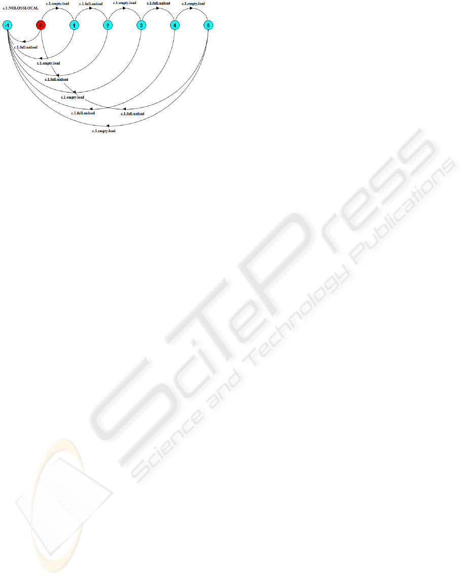
Figure 10: FSP specifications along with the generated LTS
automate for NOLOSS.
erty of each carrier that verifies that each carrier fol-
lows the sequence (load → unload) one or more times.
And we have to compose this property on N number
of carriers to verify it globally. As shown by the LTS
in figure-10 there is an error(-1) state to check the sys-
tem safety, each and every action that is not compati-
ble with the specifications results into the error state.
As a result we have a system that is exhaustively ver-
ified.
7 LESSONS LEARNED
AND CONCLUSIONS
Gaia’s role model defines the behaviour and re-
sponsibilities that are liveness and safety properties.
Transformation from Gaia to FSP plays a key role for
the formal verification of our system. In this paper
we have not detailed the transformation process and
its semantics but we would be presenting it in our
future work. Gaia method has a concrete syntax to
express properties, is suitable to model behaviors and
is applicable to a wide range of multi-agent systems
but it does not provide constructs for the formal
verification. Therefore we have to translate the Gaia
concepts into FSP specifications. With these formal
techniques and methods we studied the features of
formal verification and property checking for multi-
agent systems. There is a need of the development of
a clear method, centered around formal verification
and organizational abstractions, for the analysis and
design of multi-agent systems specifications. For
the simulation of our case study example we are
using a service based architecture Microsoft Robotics
Developer Studio (Microsoft, 2007). The objective
is to devise multi-agent systems based on formal
methods that assure correctness. Multi-agent systems
have concurrency, synchronization and deadlock
issues to be handled and its suitable to use formal
development methods with organizational structure,
appropriate set of agent abstractions and formal
verification methods for checking the correctness of
the system.
REFERENCES
Abrial, J.-R. (1996). The B book - Assigning Programs to
meanings. Cambridge University Press.
Brard, B., Bidoit, M., Finkel, A., Laroussinie, F., Petit,
A., Petrucci, L., Schnoebelen, P., and McKenzie, P.
(2001). Systems and Software Verification: Model-
Checking Techniques and Tools. Springer-Verlag.
Clarke, E., Grumberg, O., and Peled, D. (2000). Model
Checking. MIT Press.
Giannakopoulou, D., Magee, J., and Kramer, J. (1999).
Fairness and priority in progress property analysis.
Technical report, Department of Computing, Imperial
College of Science, Technology and Medicine, 180
Queens Gate, London SW7 2BZ, UK.
Giunchiglia, F., Mylopoulos, J., and Perini, A. (2001).
The tropos software development methodology: Pro-
cesses, models and diagrams. Technical report, Infor-
matica e Telecomunicazioni, University of Trento.
Jennings, N., Sycara, K., and Wooldridge, M. (1998). A
roadmap of agent research and development. Int.
Journal of Autonomous Agents and Multi-Agent Sys-
tems, 1(1):7–38.
Magee, J. and Kramer, J. (2006). Concurrency: State Mod-
els and Java Programs. John Wiley and Sons, 2nd
edition.
Microsoft (2007). Microsoft Robotics Developer Studio.
Wooldridge, M. (2000). Reasoning about Rational Agents.
MIT Press.
Wooldridge, M., Jennings, N., and Kinny, D. (2000). the
gaia methodology for agent-oriented analysis and de-
sign. Autonomous Agents and Multi-Agent systems,
3:285–312.
Wooldridge, M. and Jennings, N. R. (1995). Intelligent
agents: Theory and practice. Knowledge Engineering
Review, 10(2):115–152.
Zambonelli, F., Jennings, N., and Wooldridge, M. (2003).
Developing multiagent systems: The gaia methodol-
ogy. ACM Transactions on Software Engineering and
Methodology, 12(3):317–370.
ICAART 2009 - International Conference on Agents and Artificial Intelligence
482
