
THE
RE-USE OF EXPERIENCE THROUGH THE USE OF CBR IN
INFORMATION SYSTEMS MODELLING
Paulo Tom
´
e
1
, Ernesto Costa
2
and Lu
´
ıs Amaral
3
1
Department of Computing, Polytecnic Viseu, Viseu, Portugal
2
Department of Computing, University of Coimbra, Coimbra, Portugal
3
Department of Information Systems, University of Minho, Guimares, Portugal
Keywords:
Information Systems Development, Modelling process, CBR tool.
Abstract:
Information Systems Development (ISD) is an important organization activity. IT professionals develop mod-
els that describe specific organizational aspects. The IT professionals experience plays an important role in
the development of a model. Generally, IT professionals apply past experience acquired in the previous ISD
processes. This paper describes a Case-Based-Reasoning (CBR) tool that enables the use of experience in the
model development in the context of ISD process.
1 INTRODUCTION
ISD is the fundamental process performed when en-
gaging IT to achieve a specific purpose in a spe-
cific context (Fitzgerald et al., 2002). According to
Fitzgerald et al. (Fitzgerald et al., 2002) ISD involves
much more than simply the deployment of technol-
ogy. The ISD generally involves several types of pro-
cesses. There is not a generally accepted process
model, however the activities like planning, analyz-
ing, design and implementation are part of ISD pro-
cess. Each of these activities have a specific purpose
and are generally implemented making use of meth-
ods, techniques, modelling languages and software
modelling tools.
It must be noted concepts like method, technique
and modelling language are not used with the same
meaning in the ISD bibliography. In this paper we
consider the following:
• methods - define what must to be done;
• techniques - define how will be done;
• modelling languages - are the means used
to implement techniques.
But despite this problem, it could be said that in the
last few decades several authors have proposed meth-
ods, techniques and modelling languages that con-
tribute to a better ISD process. Although some au-
thors report some problems concerning to the use of
methods (Baskerville et al., 1992; Wastell, 1996), it is
a fact that IT professionals make use of them. These
methods and modelling languages can be proprietary
methods or created/adapted by the IT professional.
Whatever the method used, it could be said that
IT professionals describe organization and IT by a set
of different aspects. Generally, each Information Sys-
tem (IS) aspect is described according to several detail
levels. The data and functional aspects are frequently
described. The levels conceptual, logical and physical
are usually used to described the data aspect.
IT professionals use modelling languages to ex-
press their perception of some organizational aspect.
The model is an IT professional conceptualization of
an IS aspect. There is not any guideline, based in
problem description, for building a model. The IT
professional experience determines the model’s qual-
ity (Chaiyasut and Shanks, 1994). Examples are gen-
erally used to teach IT professionals modelling tech-
niques (Kendall and Kendall, 1992; Downs et al.,
1992).
Our proposal intends to show a software tool that
enables the re-use of experience, based on CBR tech-
niques, in IS modelling. It is important mention that
others authors already tried to do that, although they
used other IA techniques, but nowadays there are not
any software modelling tool that enables the re-use of
experience in IS modelling.
Our tool has two main benefits. First, the IT pro-
297
Tomé P., Costa E. and Amaral L. (2009).
THE RE-USE OF EXPERIENCE THROUGH THE USE OF CBR IN INFORMATION SYSTEMS MODELLING.
In Proceedings of the International Conference on Agents and Artificial Intelligence, pages 297-305
DOI: 10.5220/0001665202970305
Copyright
c
SciTePress

fessional does not need do previously realized tasks.
Second, the IT professional can learn with previously
resolved situations by other colleagues. Beside that,
we can consider ISMT a tool that contributes to a
good Knowledge Management (KM). The KM leads
to rational allocation of organizational knowledge as-
sets (Althoff and Weber, 2005). This tool allows us a
to maintain a ”experience base” platform that facili-
tate ISD projects.
The tool presented in this paper could be classified
as belonging to the design class of the classification
schema proposed by Althoff (Althoff et al., 1995).
The modelling is a design task because the model con-
ception is carried on without any guidelines.
It is possible to find in the research CBR bibliog-
raphy some works that share some common charac-
teristics. These works are mainly found in the soft-
ware development environments where it is possible
to reuse software code. The use of CBR in the soft-
ware development environment is the goal of the Re-
builder project (Rebuilder, 2006). This project intends
to use the CBR methodology in development of UML
diagrams (Gomes et al., 2002; Gomes et al., 2003a;
Gomes et al., 2003b). The Experience Factory (Al-
thoff et al., 1999) propose a structure and a software
application that aims to reuse experience in the con-
text of software development processes.
Regarding these two works, it is important to say
that ISMT is not concerned with the software devel-
opment process (i.e code writing). Our intention is
to help the development of models that describe some
organizational aspects. However the use of UML di-
agrams could be a common aspect with the Rebuilder
project.
This paper shows a CBR tool developed to assist
the ISD process. In section 2 we briefly review the
main ISD concepts needed to understand our contri-
bution that is described in section 3. In section 3 we
show also the results of the ISMT application to a set
of data models.
2 INFORMATION SYSTEMS
MODELLING LANGUAGES
IT professionals can use several modelling languages.
Theses language enable the production of models that
are a conceptualization of an IS aspect. There are two
types of modelling languages: textual and graphic.
Textual modelling languages produces textual de-
scription while graphic language produces graphical
descriptions. In the IS bibliography a large set of
modelling languages are described. For example,
Song et al. (Song et al., 1995) analyze twelve data
modelling languages. The Open Group proposed the
UML (OMG, 2007) that consists of thirteen mod-
elling languages.
It is not our aim to do a review of all modelling
languages. We will do a review of the most important
modelling languages. For each modelling language
we identify the most relevant characteristics.
The flowchart (Chapin, 1970) is perhaps the oldest
language used to describe processes. This language
has four main constructors: Process, Input-output,
Flow and Decision.
Another older notation is the Data Flow Diagram
(Gane and Sarson, 1979). This language, which is
widely used in the IS domain, has four types of con-
structors: Process, Data store, Flow and External en-
tity.
The National Institute of Standards and Tech-
nology created the IDEF0 (Integration Definition
for Function Modeling) (Technology, 1993) and the
IDEF1X (Integration Definition for Information Mod-
eling) (FIPS, 1993) languages. The IDEF0 language
consists of the following constructors: Activity, Input,
Control, Output, Call, and Mechanisms. The IDEF1X
language can be used to model the data aspect. This
languages has the following constructors: Entity, At-
tribute, Relationship and Relation categorizationship.
Chen (Chen, 1976) created the most popular
Entity-Relationship (ER) language. An ER model
consists of Entities, Attributes and Relationships. It
is important to notice that in the Chen notation the at-
tributes are drawn as nodes and are not placed inside
entities like in other ER notations.
In the BSP method (IBM, 1984) the data entities
and the processes are specified through a list of data
entities names and a list of processes names.
The Oracle Corporation created two modelling
languages in the CASE*Method: Entity Relationship
Modelling (Barker, 1995) and Function and Process
Modelling (Barker and Longman, 1992). The En-
tity Relationship Language has two major construc-
tors: Entity and Relationship. The Function and
Process Modelling lanugage comprises the following
constructors: Function, Event, Relation, Objective,
Dependency and Actor.
The Object Management Group created UML
(Unified Modeling Language) (OMG, 2007). UML
comprises thirteen languages that can be grouped into
structure, behaviour and implementation groups.
3 THE ISMT
In this section we describe the knowledge domain
and the ISMT’s structure (shown in figure 3). The
ICAART 2009 - International Conference on Agents and Artificial Intelligence
298

proposed conceptual framework is built using Gram-
mar Attribute (GA) formalism (Wilhelm and Maurer,
1996). The GA is a rigorous formalism that simulta-
neously has synthesizing and inheriting mechanisms
enabling the identification of object’s attributes. We
intend to get two model aspect’s: structural and se-
mantical. The structural is related with the model’s
form. While the semantical aspect is related with the
contents and the purpose of the model. The follow-
ing description is not oriented to a specific modelling
tool.
One part of the Knowledge domain is the system
vocabulary (Richter, 1995)). The observation of the
IT professionals modelling activity, leads us to con-
clude that we should consider two kinds of cases:
models and constructors. The case model is naturally
implemented because the IT professionals major goal
is the development of models. But it is not possible to
get always an entire model, then it is useful to extract
individual constructors.
As previously mentioned, an IT professional
builds models to specify an IS aspect. Each IS aspect
can be described in several detail levels. A model,
specified through a modelling language, can be de-
veloped in a context of a method. Besides that, it is
important to associated to a model the type of organi-
zation to which the IS is developed. This kind of in-
formation enables the contextualization of the model.
The Model object, described in Specification 1,
has the proper attributes: aspect (asp), level (level),
method (me), scope (sc), organization type (org t),
terms that characterize the ISD project (I d) and key-
words. The attribute aspect stores information about
the model aspect. For example, as previously men-
tioned, the IT professionals develop models for data
and functional IS aspects. The attribute level stores
information about the model level. For a Data Model
the level attribute can have one of the following val-
ues: conceptual, logical or physical. The method at-
tribute registers the method used in the ISD process.
The scope attribute registers the type of ISD process,
which can be the entire organization, a department or
a section description. The organization class is reg-
istered in the type of organization org type attribute.
In the terms that characterizes the ISD attribute a list
of terms that characterizes the organization to which
the IS is developed are registered. The keywords at-
tribute is synthesized from the view object and will
be described later on. The keywords and number of
components (ncomp) attributes are synthesized from
the constructor object.
A constructor, described in Specification 2, can be
divided in two types: component or connector. Gen-
erally, a constructor has a name (name) and some
Specification 1: Model object description.
Model → asp level me lan sc org t I d S c.
Model.aspmodel = asp.Value;
Model.level = level.Value;
Model.method = me.Value;
Model.language = lan.Value;
Model.scope = sc.Value;
Model.org type = org t.Value;
Model.description = I d.description;
S c.aspmodel = asp.value;
S c.level = level.Value;
S c.method = me.Value;
S c.language = lan.Value;
S c.scope = sc.Value;
S c.org type = org t.Value;
S c.description = I d.description;
S c.ncomp = 1;
I d → des.
I d → des I d.
I d.description = des.value;
I d
0
.description = concat(des.value,I d
1
.description);
S c → Co.
Co.asplevel = S c.asplevel;
Co.level = S c.level;
Co.method = S c.method;
Co.scope = S c.scope;
Co.org type = S c.org type;
Co.description = S c.description;
Co.ncomp = S c.ncomp;
S c.keywords = Co.keywords;
I d → des I d.
I d
0
.description = concat(des.value,I d
1
.description);
S c → Co S c.
Co.asplevel = S c.asplevel;
Co.level = S c.level;
Co.method = S c.method;
Co.scope = S c.scope;
Co.org type = S c.org type;
Co.description = S c.description;
Co.ncomp = S c.ncomp;
S c
0
.keywords = concat(S c
1
.keywords,Co.keywords);
characteristics (Chs). For example, in the ER no-
tation an attribute has the following characteristics:
data type, length and type of attribute (normal, for-
eign key or primary key). Furthermore, we associ-
ated to the Constructor object an attribute for stor-
ing keywords (Ks). These keywords are used to con-
textualize the application of the constructor. The
THE RE-USE OF EXPERIENCE THROUGH THE USE OF CBR IN INFORMATION SYSTEMS MODELLING
299
Specification 2: Constructor object description.
Co →
0
component
0
name Chs Ks Sup Sub Re Li.
Co.type =
0
component
0
;
Co.name = name.value;
Co.characts = Chs.characts;
Co.keywords = Ks.keywords;
Co.supkeywords = Sup.keywords;
Co.subkeywords = Sub.keywords;
Co.relationship = Re.relationship;
Co.likeywords = Li.keywords;
Co.no f links = Li.number;
Co.ncomp = Co.ncomp + 1;
Co →
0
connector
0
name Chs Ks Sup Sub Re Li.
Co.type =
0
connector
0
;
Co.name = name.value;
Co.characteristics = Chs.characteristics;
Co.keywords = Ks.characteristics;
Co.supkeywords = Sup.keywords;
Co.subkeywords = Sub.keywords;
Co.relationship = Re.relationship;
Co.linkeywords = Li.keywords;
Co.likeywords = Lid.keywords;
Chs → name val.
Chs → name val Chs.
Chs.characts = (name.value,val.value);
Chs
0
.characts = concat(Chs
1
,(name.value,val.value));
Ks → val.
Ks → val Ks.
Ks.keywords = val.value;
Ks
0
.keywords = concat(Ks
1
,val.value);
Sup → Ks.
Sub → Ks
Sup.keywords = Ks.value;
Sub.keywords = Ks.value;
Re → name Ks.
Re.relationship = (name.value,Ks.value);
Li → Ks.
Li → Ks Li.
Li.keywords = Ks.value;
Li
0
.keywords = concat(Li
1
.keywords,Ks.value);
constructor can belong to another component or can
aggregate other components. In the supkeywords
attribute and subkeywords are stored the keywords
of the owner and owned constructors, respectively.
The relationship attribute stores information that con-
cerns rules used in the modelling task. For exam-
ple, in modelling tasks decomposing rules are ap-
plied. Keywords of linked constructors are stored in
the likeywords attribute.
The attributes identified in each Specification (1
and 2) were considered a case’s characteristic. We
implemented the Kolodner (Kolodner, 1993) case’s
structure. We consider that a case has two parts: prob-
lem and solution. The problem consists of a objective
and a set of characteristics (which are the attributes
identified in Specification 1 and 2). The solution is
the description in XML of the model and construtor
objects.
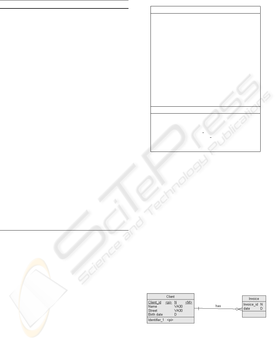
As can be deduced from the previous explanation,
Table 1: Example of case.
Problem
Objective: Construtor definition
Characteristics:
Constructor’s type: Entity
Constructor’s characteristics:
Constructor’s aggregated keywords: code,
name, date, street
Keywords of the construtor in upper level:
Keywords of associated constructors in
current model: Invoice
Model’s aspect: Data
Level: Conceptual
Language: IDEF1X
Method:
Scope:
Type of organization: Comercial
Description:
Keywords: client
Solution
< a : Name > Client < /a : Name >
< a : Code > CLIENT < /a : Code >
< c : Identi f iers >< o : Identi f ierId = ”o10” >
< a : Name > Identi f ier 1 < /a : Name >
< a : Code > IDENT IFIER 1 < /a : Code >
...
the case model comprises a set of case constructors.
Each case is individually stored in the case memory.
We use, through the synthetizing mechanism, some of
the attributes of the case construtor as characteristics
of the case model. Through the inheriting mechanism
we use some of case model attributes as characteris-
tics of the case construtor. As explained bellow, the
case’s characteristics are used as indexes to cases in
the case memory.
Regarding to the representation of the solution in
XML, it is important mention that we considered this
language because it is one of the most used language
in the software modelling tools. Beside that, the
XML format allow an easy implementation of adap-
tion rules, because the values are registered in a sim-
ilar form of the attribute/value format. In table 1 it
is shown the case client of the data entity client illus-
trated in figure 1.
Figure 1: Simple data model example.
Each case is stored in the Case memory through
frames formalism (Minsky, 1974; Minsky, 1975). It
is implemented in Case memory the concept of con-
tainer of Richter (Richter, 1995) to store all types
of knowledge. Every frame has a flag that specifies
ICAART 2009 - International Conference on Agents and Artificial Intelligence
300
which type of knowledge it stores.
We apply clustering techniques (Tan et al., 2006)
to store the cases in the case memory. These tech-
niques were used to enable a faster case retrieval. Ac-
cess to the case-memory is achieved by using Groups
of cluster links as shown in figure 3. This strategy
significantly reduces the number of case assessments
and consequently retrieval time. Our proposal has two
levels of information. The first level is formed by a set
of links to the case memory and the second level is the
case memory database. The case links are paths to
cases memory. The clustering technique is applied to
case links information. The first level of information
requires a low amount of storage space however de-
creases the waiting time of the retrieval process. We
do not considered the division of the database case
memory because it is useful to access a case from dif-
ferent ways. Each group has clusters of links to cases.
Each cluster, as shown in table 2, has a reference to
the medoid of the cluster and links to a set of cases
that constitute the cluster.
Table 2: Cluster definition.
Clus =< LMed,SCl >
Med = link to case
SCl = {link to case}
Where:
Clus - Cluster
LMed - Link to medoid
SCl - Set of Cluster link;
C - Characteristic
Each Group of clusters is identified by a binary
array codification. The binary codification scheme
follows the proposal of Kolodner (as shown in table
3). Table 4 shows a case with three Characteristics.
So each position of the binary array is associated to a
particular feature of a case, where 1 (0) indicates the
availability (non-availibility) of the feature.
Table 3: Case Structure.
Case =< P, S >
P =< O,Cs >
Cs = {C}
Where:
P - Problem
O - Objective
Cs - Set of characteristics;
C - Characteristic
The first positions on the right side of the array are
used to represent objectives. The remaining positions
are used to represent characteristics. For example, us-
ing sixteen bits with the division illustrated in table 5,
Table 4: Case Example.
Cas
1
=< P,S >
P =< O1,Cs >
Cs =< C
1
,C
2
,C
3
>
the case Cas
1
, shown in table 4, addresses the group
with the following binary array 0000000001110001.
Table 5: Addressing Group Cluster.
C
12
C
11
C
10
C
9
C
8
C
7
C
6
C
5
C
4
C
3
C
2
C
1
O
4
O
3
O
2
O
1
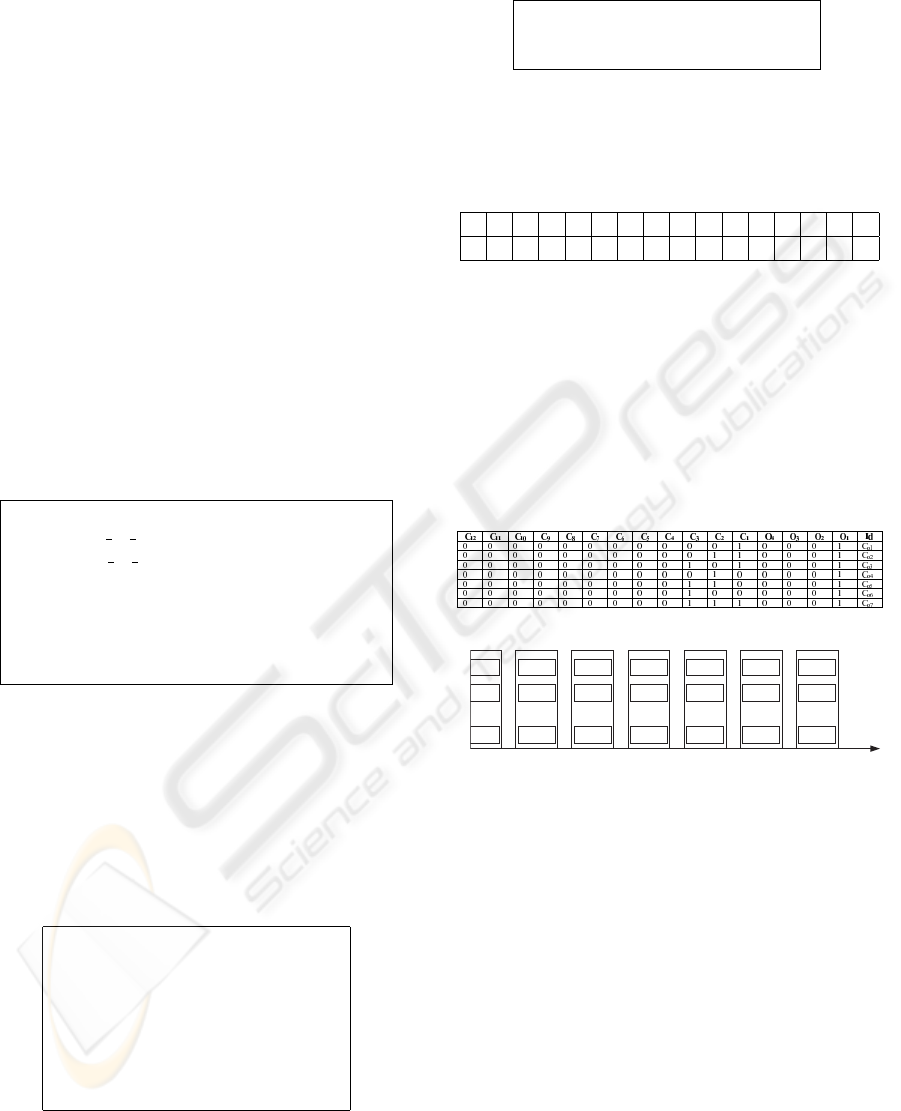
However to deal with missing characteristics the
cases belong to more than one group. All combination
of the available characteristics and objective define
different groups. In table 6 it is presented the com-
binations of characteristics and objective for the case
Cas
1
. The case Cas
1
is associated to seven groups
(figure 2), in each group clustering might be achieved
with a distinct number of clusters.
Table 6: Combinations example to Cas
1
case.
Co
1
Cluster
A1
Cluster
A2
Cluster
An
...
Cluster
B1
Cluster
B2
Cluster
Bn
...
Cluster
C1
Cluster
C2
Cluster
Cn
...
Cluster
D1
Cluster
D2
Cluster
Dn
...
Cluster
E1
Cluster
E2
Cluster
En
...
Cluster
F1
Cluster
F2
Cluster
Fn
...
Cluster
G1
Cluster
G2
Cluster
Gn
...
Co
2
Co
3
Co
4
Co
5
Co
6
Co
7
Groups of clusters
Figure 2: Example of a database of group of case links.
Besides the cases, the Case memory has knowl-
edge related to the metric and adaptation rules. The
metric is stored on the frame that describes the
domain knowledge according to attribute value ap-
proach. The procedures names that implement the
adaptation rules are also stored in the mentioned
frames. These procedures are implemented using
stored procedure of the Oracle engine.
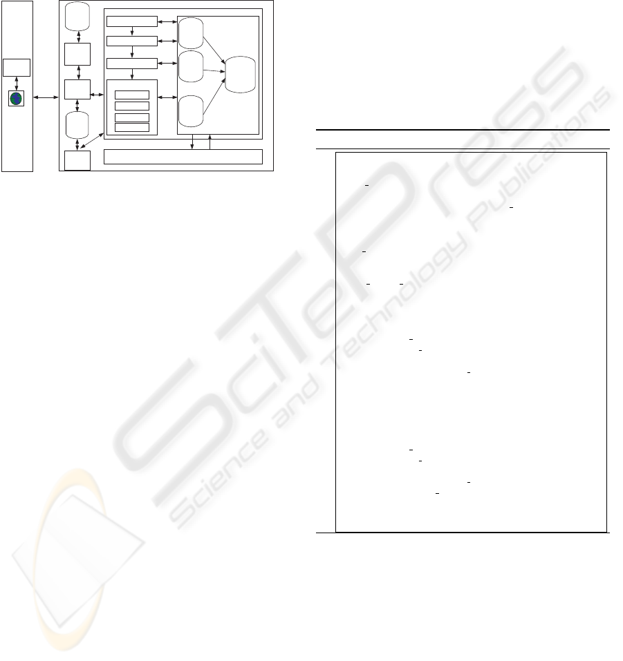
Regarding to the ISMT’s structure (shown in fig-
ure 3), it is important to state that it was our intention
to implement a system independent of application do-
main and also independent of the type of modelling
tool. The tool has two major components: the client
and the server. The IT professional uses the client
components: a browser and a software design tool.
The browser is used to communicate with the server
THE RE-USE OF EXPERIENCE THROUGH THE USE OF CBR IN INFORMATION SYSTEMS MODELLING
301
component. It is through the browser that the IT pro-
fessional requests for solutions to problems and stores
models. Besides that, it is through the browser that the
IT professional configures the tools (modelling lan-
guages) in the server. The server part is implemented
using the technologies Oracle (Oracle, 2007) and Mi-
crosoft ASPX (Ahmed et al., 2002).
Retrieval
Reusing
Revision
Process 1
…
Process 2
Process n
Retention
Case Memory
Group of clusters
Case Links
n
...
XML
parser
Group of clusters
Case Links
2
Group of clusters
Case Links
1
Software Design
tools lybrary
Knowledge Manager
Modelling
languages
manager
Modelling
Manager
Server
Software
Modelling
Tool
Browser
Client
Modelling
languages
lybrary
Figure 3: ISMT’s structure.
The 4Rs cycle proposed by Aamodt and Plaza
(Aamodt and Plaza, 1994; Mantaras et al., 2005)
was implemented in the server. The following mod-
ules were also implemented: Software design tools li-
brary, XML parser, Knowledge manager, Modelling
manager, Models tools manager and Modelling lan-
guages library. The software design tools library has
the parsing rules that enable the parsing of XML files
by XML parser. The ISMT’s users manage the con-
tents of the Case memory through Knowledge man-
ager. In this module the user can correct and disable
previously resolved problems. The Modelling man-
ager is responsible the entire process of developing a
model and it allows solutions to problems to be re-
quested and stores new models. The Models tools
manager enables of new languages to be configured.
This module uses the meta-case definition to specify
the meaning for a modelling language. The Modelling
languages library has the knowledge about each spe-
cific modelling language as well as the conversation
rules between different modelling languages.
The Retrieval process was implemented to enable
the adoption of the principles previously described.
Algorithm 3 shows the steps of the algorithm when a
new problem is presented:
• identification of the clustering group;
• identification of the cluster within the group
using a similarity measure;
• finally the case is compared with all cases
in the cluster.
In the second step the Default Difference measure
strategy (Bogaerts and Leake, 2004) is applied only
to the medoid of the clusters. In the third step, dif-
ferent similarity evaluations are used. It is important
mention that, that if a case has not a mandatory char-
acteristic equal to an characteristic required, this case
it is not considered eligible for the resolution of the
current problem.
The re-use phase consists of: copy of equal case
parts and adaptation of similar case parts for the two
kinds of cases. Although for the case model we im-
plemented a third task. In this situation we imple-
mented a retrieval process for individual constructors
not considered in the solution founded. The construc-
tors founded are added to the solution that will be pro-
posed. The adaptation of each solution component is
implemented through PL/SQL procedures.
Algorithm 3: Retrieval Algorithm.
/* —————————————————————-
Cas is the case for which it is search a solution
Prop Cas is the proposed case
—————————————————————-*/
procedure retrieval(Cas in Case, Prop cas out Case)
Clusgroup ClusterGroup;
Clus Cluster;
Sim Similarity;
Sim a Similarity;
begin
Clusgroup ← Deter-
mine cluster group(Cas.Obj,Cas.Cars);
Clus ← 0;
Sim ← 0;
For each Cluster in Clusgroup do
begin
Sim a ← Similarity(Cas, Cluster(i).medoid);
if Sim a > Sim then
begin
Sim ← Sim a;
Clus ← Cluster(i);
end;
end;
Sim ← 0;
For each Case in Clus do
begin
Sim a ← Similarity(Cas, case(i));
if Sim a > Sim then
begin
Sim ← Sim a;
Prop cas ← Case(i);
end;
end;
end;
The Revise process is implemented by the ISMT
user. It is the user that analyzes if the solution pro-
posed fits its problem and corrects aspects that he con-
siders incorrect.
The retention process algorithm, shown in algo-
rithm 4, was also implemented according to the prin-
ciples previously described. This process was paral-
lelized, e.g. the retention in each Group of cluster
is implemented by different program processes. The
process begins with the determination of all possi-
ble combinations between the available characteris-
tics and the objective of the case. Then for each com-
ICAART 2009 - International Conference on Agents and Artificial Intelligence
302
bination, the case is inserted in respective Group of
clusters. This insertion process is parallelized. Each
insertion in a Group determines:
1) evaluation of the similarity with the cluster
medoids;
2) identification of the cluster to insert the
case;
3) actualization of the medoid of the cluster
where the case was assigned.
The similarity measure strategy used in step two is
also Default Difference. In a group a new cluster
is created whenever a binary similarity evaluation re-
sults in a zero.
Algorithm 4: Retention Algorithm.
/* ———————————————-
Cas is the case that will be retained
———————————————–*/
procedure retention(Cas in Case)
Combs Combinations;
Combination TCombination;
Clusgroup ClusterGroup;
Clus Cluster;
Sim Similarity;
Sim a Similarity;
begin
Combs ← Gener-
ate all combinations(Cas.Obj,Cas.Cars);
For each Combination in Combs do
begin
Clusgroup ← Deter-
mine clus group(Combination(i));
Sim ← 0;
For each Cluster in Clusgroup do
begin
Sim a ← Similarity(Cas, Clus-
ter(j).medoid);
if Sim a > Sim then
begin
Sim ← Sim a;
Clus ← Clus(i);
end;
insert case cluster(Clus,Cas);
recalculate medoid(Cluster(i));
end;
end;
pos med =
n f eatures
∑
i=1
pos(value o f f eature(i)) ∗ weight( f eature(i)) (1)
where:
weight(feature(i)) - is the weight of the feature(i).
pos(value of feature(i))
-
is the position of feature in a ordered set
of values
The medoid is computed through the determina-
tion for each case the values given by the expression
1. After that the set of values is ordered and is deter-
mined the medoid element.
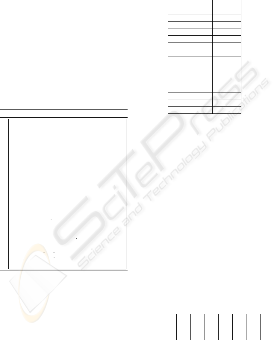
Table 7: Number of constructors of Example 1.
Model N. Comp N. Connect
1 14 7
2 135 63
3 176 23
4 80 19
5 70 17
6 81 6
7 161 23
8 106 25
9 41 5
10 103 13
11 36 5
12 31 5
13 210 87
14 20 7
15 88 5
4 RESULTS AND CONCLUDING
REMARKS
We used ISMT for the specification of data models to
create three examples in different contexts:
• Example 1: fifteen data models for different
organization departments (such as sales, ac-
counting, manufacturing and so on);
• Example 2: six data models of six hospital
medical services;
• Example 3: nine data models of the same
department (sales department).
All the data models were specified using the IDEF1X
(FIPS, 1993) in the PowerDesigner (Sybase, 2006)
software tool. The models developed in examples
1) and 3) were defined by different IT professionals
while the models developed in example 2) were de-
fined by only one IT professional. A total of thirty
data models, as shown in tables 7 to 9, were used to
evaluate the ISMT tool. It is important mention that a
total of five thousands and six case constructors were
introduced in the systems.
Table 8: Number of constructors of Example 2.
Model 16 17 18 19 20 21
N. Comp 281 406 367 391 230 394
N.
Connect
69 93 78 88 61 89
In this experimental study we want to measure the
re-utilization of the tool. Then each model within
THE RE-USE OF EXPERIENCE THROUGH THE USE OF CBR IN INFORMATION SYSTEMS MODELLING
303
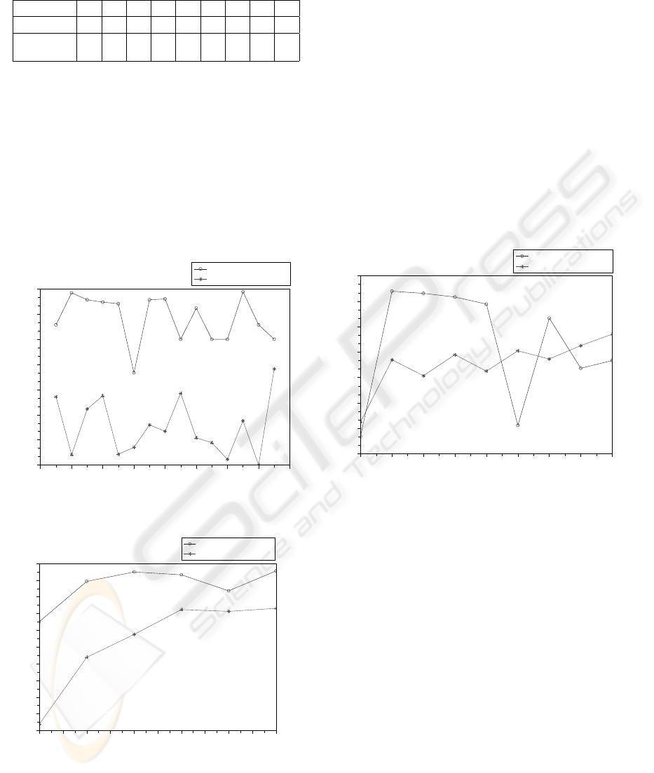
Table 9: Number of constructors of Example 3.
Model 22 23 24 25 26 27 28 29 30
N. Comp 73 112 112 58 40 78 55 51 61
N.
Connect
19 33 29 12 9 17 12 11 15
each example was introduced sequentially according
to the order specified in the table.
Figure 4 presents the results of Example 1) where
the models belong to different departments types and
were created by different IT professionals. Despite
the diversity of the data models, there is a mean per-
centage of re-use, around 44% and 23% for connec-
tors and components respectively. It also has to be
noticed that the percentage does not decrease with an
increasing number of models in the case memory.
0 2 4 6 8 10 12 14 16
15
20
25
30
35
40
45
50
Results of example 1
Data model
Adaptation Percentage
Adapted connectors
Adapted attributes and entities
Figure 4: Results of example 1.
16.0 16.5 17.0 17.5 18.0 18.5 19.0 19.5 20.0 20.5 21.0
50
55
60
65
70
75
80
85
90
95
100
Results of example 2
Data model
Adaptation percentage
Adapted connectors
Adapted attributes and entities
Figure 5: Results of example 2.
Figure 5 shows the results of Example 2) where
the models belong to departments with identical pur-
poses and were defined by the same IT professional.
We can see that the percentage of re-utilization is
high, above 52% and 83% for connectors and com-
ponents respectively. This result has to be expected
considering the similarities of the departments and the
consistency of the modelling phase. And it is shown
that the percentage of re-use increases with the num-
ber of cases in memory.
Figure 6 presents the results of Example 3) where
the models belong to the same department and were
created by different IT professionals. We can see that
the percentage of re-utilization is above 37% and 43%
respectively for connectors and components respec-
tively. This result illustrates that the consistency in the
modelling phase influences the outcome. The number
cases in the memory is not always related to a high-
percentage of re-use, at least in terms of the re-use of
connectors.
22 23 24 25 26 27 28 29 30
30
40
50
60
70
80
90
100
Results of example 3
Data model
Adaptation percentage
Adapted connectors
Adapted attributes and entities
Figure 6: Results of example 3.
In this paper we proposed a software tool - ISMT,
based on CBR techniques, which enables the re-use
of experience in IS model development. Based on a
careful analysis of the modelling languages a frame-
work, described through the GA formalism, for the
model and constructor objects is presented.
The proposed ISMT supports the use of several
modelling languages and software modelling tools.
Furthermore, ISMT applies Clustering techniques to
improve retrieval case time.
The ISMT was tested with a set of thirty data mod-
els, e.g. thirty cases models, that comprise five thou-
sands and six constructors. The results obtained lead
us to conclude that the support of the tool can be a
good contribution ti ISD.
ICAART 2009 - International Conference on Agents and Artificial Intelligence
304

REFERENCES
Aamodt, A. and Plaza, E. (1994). Case-based reasoning:
Foundational issues, methodological variations and
systems approaches. AI-Communications, 7(1):39–
52.
Ahmed, M., Garret, C., FairCloth, J., and Payne, C. (2002).
ASP.NET Web Developers’s Guide. Syngress Publish-
ing.
Althoff, K. D., Auriol, E., Barletta, R., and Manago, M.
(1995). A review of industrial case-based reasoning
tools. Technical report, AI Intelligence.
Althoff, K. D., Nick, M., and Tautz, C. (1999). Cbr-peb:
An application implementing reuse concepts of expe-
rience factory for the transfer of cbr system know-
how. In 7th German Workshop on Case-Based Rea-
soning, Wurzburg.
Althoff, K. D. and Weber, R. O. (2005). Knowledge man-
agement in case-based reasoning. The Knowledge En-
gineering Review, 20:305–310.
Barker, R. (1995). Case*Method - Entity Relationship Mod-
elling. Addison-Wesley.
Barker, R. and Longman, C. (1992). Case*Method - Func-
tion and Process Modelling. Addison-Wesley.
Baskerville, R., Travis, J., and Truex, D. (1992). Systems
without method: The impact of new technologies on
information systems development projects. The Im-
pact of Computer Supported Technologies on Infor-
mation Systems Development, pages 241–270.
Bogaerts, S. and Leake, D. (2004). Facilitating cbr for
incompletely-described cases: Distance metrics for
partial problem descriptions. In ECCBR 2004, pages
62–74.
Chaiyasut, P. and Shanks, G. (1994). Conceptual data mod-
elling process: A study of novice and expert data mod-
ellers. In Halpin, T. and Meersman, R., editors, First
International Conference on Object-Role Modelling,
pages 310–323, Brisbane - Queensland.
Chapin, N. (1970). Flowcharting with the ansi standard: A
tutorial. Computing Surveys, 2(2).
Chen, P. P.-S. (1976). The entity-relationship model - to-
ward a unified view of data. ACM Transactions on
Database Systems, 1(1):9–36.
Downs, E., Clare, P., and Coe, I. (1992). Structured Systems
Analysis and Design Method Application and Context.
Prentice Hall, 2ł edition.
FIPS (1993). Integration Definition for Information Model-
ing (IDEF1X). Federal Information Processing Stan-
dards Publications.
Fitzgerald, B., Russo, N., and Stolterman, E. (2002). In-
formation Systems Development: Methods in Action.
McGraw-Hill.
Gane, C. and Sarson, T. (1979). Structured Systems Analy-
sis: Tools and Techniques. Prentice-Hall.
Gomes, P., Pereira, F. C., Paiva, P., Seco, N., Carreiro,
P., Ferreira, J. L., and Bento, C. (2002). Using
wordnet for case-based retrieval of uml models. In
STarting Artificial Intelligence Researchers Sympo-
sium (STAIRS’02).
Gomes, P., Pereira, F. C., Paiva, P., Seco, N., Carreiro, P.,
Ferreira, J. L., and Bento, C. (2003a). Case-based
reuse of uml diagrams. In Fifteenth International Con-
ference on Software Engineering and Knowledge En-
gineering (SEKE’03).
Gomes, P., Pereira, F. C., Paiva, P., Seco, N., Carreiro,
P., Ferreira, J. L., and Bento, C. (2003b). Human-
machine interaction in a case environment. In Inter-
national Joint Conference on Artificial Intelligence IJ-
CAI’03 Workshop: ”Mixed-Initiative Intelligent Sys-
tems”.
IBM (1984). Business Systems Planning: Information Sys-
tems Planning Guide. IBM Cooperation.
Kendall, K. E. and Kendall, J. E. (1992). Systems Analysis
And Design. Prentice-Hall.
Kolodner, J. (1993). Case-Based Reasoning. Morgan Kauf-
mann Publishers.
Mantaras, R. L., Mcsherry, D., Bridge, D., Leake, D.,
Smyth, B., Craw, S., Faltings, B., Maher, M. L., Cox,
M. T., Forbus, K., Keane, M., Aamodt, A., and Wat-
son, I. (2005). Retrieval, reuse, revison and retention
in case-based reasoning. The Knowledge Engineering
Review, 20(3):215–240.
Minsky, M. (1974). A framework for representing knowl-
edge. Technical report, Massachusetts Institute of
Technology.
Minsky, M. (1975). A framework for representing knowl-
edge. In Winston, P., editor, The Psychology of Com-
puter Vision, pages 211–277. McGraw-Hill. ISBN
0070710481.
OMG (2007). Unified modeling language: Superstructure.
Technical report, Object Management Group.
Oracle (2007). www.oracle.com.
Rebuilder (2006). rebuilder.uc.pt.
Richter, M. M. (1995). The knowledge contained in sim-
ilarity measures. Comunicao por convite na ICCBR
95.
Song, I. Y., Evans, M., and Park, E. K. (1995). A compara-
tive aalysis of entity-relationship diagrams. Journal of
Computer and Software Engineering, 3(4):427–459.
Sybase (2006). www.sybase.com/products/ databaseman-
agement.
Tan, P. N., Steinbach, M., and Kumar, V. (2006). Introduc-
tion to Data Mining. Pearson Education.
Technology, N. I. S. (1993). Integration Definition for
Function Modeling (IDEF0). Federal Information
Processing Standards Publications. r50.
Wastell, D. G. (1996). The fetish of technique: methodol-
ogy as a social defense. Information Systems Journal,
6:25–40.
Wilhelm, R. and Maurer, D. (1996). Compiler Design.
Addison-Wesley.
THE RE-USE OF EXPERIENCE THROUGH THE USE OF CBR IN INFORMATION SYSTEMS MODELLING
305
