
ANGLES ESTIMATION OF ROTATING CAMERA
Samira Ait Kaci Azzou
Computer Science Department, Setif University, Setif, Algeria
Slimane Larabi, Chabane Djeraba
LIFL Laboratory, Lille1 University, Lille, France
Keywords:
Rotation motion, Matching, Interest points, Camera pose.
Abstract:
We address the problem of camera motion from points and line correspondences across multiple views. We
investigate firstly the mathematical mathematical formula between slopes of lines in the different images
acquired after rotation motion of camera.
Assuming that lines in successive images are tracked, this relation is used for estimating rotation angles of the
camera.
Experiments are conducted over real images and the obtained results are presented and discussed.
1 INTRODUCTION
There are many applications of computer vision and
pattern recognition where the camera orientation is
controlled by a computer. For example, in order to
track and center the object of attentive focus, the cam-
era is rotating once the object is near from the image
border. The amount of rotation depends on the veloc-
ity of the object and its depth.
When a camera is rotated by a certain angle rela-
tive to a stationary scene, different projected images
are seen on the image plane. Consequently, the ex-
tracted low-level features (interest points, segments
of contour, etc) on images change their attributes so
as position, intensity, etc).
From these low-level features, if a set of invariants
are computed in the sense that their new values are
completely determined by the original values and the
amount of the camera rotation, we can then predict the
values of these invariants which would be obtained if
the camera were rotated by a given amount.
Conversely, if we are given two views of the same
scene obtained from different camera orientations,
and if we know the point-to-point correspondence, we
can reconstruct the amount of camera rotation which
would transform the values of these invariants to pre-
scribed values.
When the camera is fixed, the analysis of different
views permits to understand the structure and the mo-
tion of moving objects. We can consider this case as
equivalent to camera rotation.
Camera motion estimation is important for var-
ious computer vision applications such as: 3D re-
construction, objects tracking and so on. Vari-
ous methods were developed and can be classified
as optical flow methods and direct methods, which
are global, and features correspondences-based ap-
proaches, which are local. From the interesting
methods we cite (R. Ewerth and Freisleben, 2004),
(C. Jonchery and Koepfler, 2008), (A. Yamada and
Miura, 2002), (A. Biswas and Venkatesh, 2006)
for optical flow methods well-adapted to small mo-
tions and (B. Rousso and Pelegz, 1996), (Bartoli
and Sturm, 2003), (Urfalioglu, 2004) for feature
correspondence-based methods that are well-adapted
to high motions of the camera giving well separated
views of the scene. In this paper we address the prob-
lem of camera motion from lines and points corre-
spondences across multiple views. We investigate
firstly the mathematical formula between slopes of
lines in the different images acquired after rotation of
the camera. Assuming that lines in successive images
are tracked, computed relation is used for estimating
rotation angles of camera. Our contribution in this
works is the extraction from low-level features invari-
ants that permits the estimating of motion rotation of
575
Azzou S., Larabi S. and Djeraba C. (2009).
ANGLES ESTIMATION OF ROTATING CAMERA.
In Proceedings of the Fourth International Conference on Computer Vision Theory and Applications, pages 575-578
DOI: 10.5220/0001753805750578
Copyright
c
SciTePress
the camera knowing the correspondence of the fea-
tures. Experiments are conducted over real images
and the obtained results are presented and discussed.
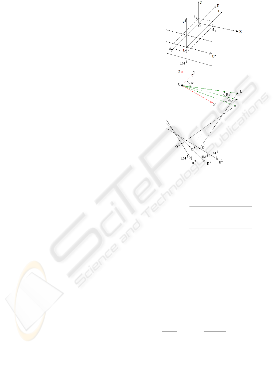
2 POSITION OF THE PROBLEM
In this work, we assume that the camera performs hor-
izontal rotational movement. The proposed geometri-
cal model is illustrated by figure 1. After each rotation
of the camera, a new image is acquired and noted IM
i
,
where i refers to the position number of the camera.
We assume that in each image some of line segments
or interest points defining segment lines are extracted.
The geometrical model of image formation is defined
by (see figure 1):
- O
i
is the impact point of the image IM
i
defined as the
intersection of the optical axis with the image plane
- L is the center of projection of the camera, O
i
L rep-
resent the focal length f
-
−−−−→
O
i
U
i
V
i
is the internal referential associated to IM
i
- The theoretical external referential
−−−−−→
(OXY Z) is de-
fined so as the origin O is the rotation center of the
camera,
−→
OX is parallel to
−−→
O
i
U
i
,
−→
OY is parallel to the
optical axis, the axis of rotation
−→
OZ is parallel to
−−→
O
i
V .
- The camera is fixed so as the rotational axis passes
through the optical axis. Due to the uncertainty of the
mechanics, the
−→
OZ axis is somewhere not far from the
impact point whose coordinates relatively to
−−−−−→
(OXY Z)
are (d
x
, d
y
, d
z
).
- ex, ez define the dimensions of the pixel
We suppose that none of the defined parameters is
known. Our aim is to develop a mathematical relation
that permit to compute the amount of the angle rota-
tion of the camera. This relation must be independent
of the camera model and will use only the coordinates
of image points in the different views.
We can see in figure 1 that when the camera is rotating
around the origin O, the projection center L and image
plane IM
i
are rotating also with the same angle.
3 ESTIMATING OF THE
ROTATION OF THE CAMERA
3.1 Basic Principle
In general case where the camera is rotating by
an angle α, any point M
i
(x
i
, y
i
, z
i
) of the 3D space
is projected into m
1
i
where its projective coordi-
nates on the image plane IM
1
are (Duda and Hart,
1988)(O. Faugeras and Papadopoulo, 2000):
Figure 1: Geometrical models for image formation and
camera rotation.
u(m
1
i
) = f .ex.
−x
0
i
.cos(α) + y
0
i
. sin(α)
x
0
i
. sin(α)+ y
0
i
. cos(α)+ D
(1)
v(m
1
i
) = f .ez.
(−z
0
i
)
x
0
. sin(α)+ y
0
i
. cos(α)+ D
(2)
where: x
0
i
= x
i
− d
x
, y
0
i
= y
i
− d
y
, z
0
i
= z
i
− d
z
and
D = d
y
− f .
As the referential
−−−−−→
(OXY Z) is attached to the initial
position of the camera, the angle α may be considered
as equal to zero. The equations 1 and 2 will serve us
for the writing of the new coordinates of points after
two rotations of the camera. Let S
i
be a line segment
in the 3D scene and let S
1
i
be the image of S
i
on the
image IM
1
whose equation relatively to (O
1
U
1
V
1
) is
v = a
i,1
.u + b
i,1
.
The coordinates of m
1
i
image on IM
1
of any point
M
i
(x
i
, y
i
, z
i
) of the segment S
i
are:
u(m
1
i
) =
f .ex.X
i,1
Y
i,1
+D
, v(m
1
i
) =
f .ez.(−Z
i,1
)
Y
i,1
+D
where:
X
i,1
= −x
0
i
. cos(α) + y
0
i
. sin(α)
Y
i,1
= x
0
i
. sin(α) + y
0
i
. cos(α)
Z
i,1
= z
0
i
As v(m
1
i
) = a
i,1
.u(m
1
i
) + b
i,1
, we can write:
Z
i,1
= a
i,1
ex
ez
X
i,1
−
b
i,1
f .ez
(Y
i,1
+ D) (3)
VISAPP 2009 - International Conference on Computer Vision Theory and Applications
576

After a second rotation of the camera with an an-
gle β, the segment S
i
will be projected on IM
2
as S
2
i
.
Let v = a
i,2
.u + b
i,2
be the equation of S
2
i
.
Following the same steps described above, we ob-
tain:
Z
i,2
= a
i,2
ex
ez
X
i,2
−
b
i,2
f .ez
(Y
i,2
+ D) (4)
where:
X
i,2
= −x
0
i
. cos(α + β) + y
0
i
. sin(α + β)
Y
i,2
= x
0
i
. sin(α + β) + y
0
i
. cos(α + β)
Z
i,2
= Z
i,1
A set of transformations will give us:
v(m
2
i
) = a.u(m
2
i
) + b (5)
where: a = (a
i,1
. cos(β)+
b
i,1
. sin(β)
f .ex
) and b = C
2
Y
i,2
Y
i,2
+D
.
Knowing that the equation (5) is valid for any
point m
2
i
of the segment S
2
i
whose equation is v(m
2
i
) =
u(m
2
i
).a
i,2
+ b
i,2
, we obtain:
a
i,2
− a
i,1
. cos(β)
sin(β)
=
b
i,1
f .ex
(6)
The equation 6 is also valid for any segment S
j
.
The use of two equations written for S
j
and S
j
gives
us:
a
i,2
− a
i,1
. cos(β)
a
j,2
− a
j,1
. cos(β)
=
b
i,1
b
j,1
(7)
For another rotation movement of the camera with
angle θ, a new equation is obtained for segments S
i
and S
j
where v = a
i,3
.u + b
i,3
and v = a
j,3
.u + b
j,3
are
the equations of S
3
i
and S
3
j
on the image IM
3
.
a
i,3
− a
i,1
. cos(θ)
a
j,3
− a
j,1
. cos(θ)
=
b
i,1
b
j,1
(8)
From 7 and 8, we obtain:
k
1
. cos(β) + k
2
. cos(θ) + k
3
= 0 (9)
where:
k
1
= a
i,3
a
j,1
− a
i,1
a
j,3
k
2
= a
i,1
a
j,2
− a
i,2
a
j,1
k
3
= a
i,2
a
j,3
− a
i,3
a
j,2
The use of a third segment S
k
with the segment S
i
gives us the relation:
k
0
1
. cos(β) + k
0
2
. cos(θ) + k
0
3
= 0 (10)
where:
k
0
1
= a
i,3
a
k,1
− a
i,1
a
k,3
k
0
2
= a
i,1
a
k,2
− a
i,2
a
k,1
k
0
3
= a
i,2
a
k,3
− a
i,3
a
k,2
The linear resolution of the equations 9 and 10
gives us the values of the angles β and θ.
3.2 Algorithm
The following algorithm gives the steps to be per-
formed in order to compute the angles of rotation of
the camera knowing the correspondence between the
set of lines extracted in the three images. The theoret-
ical study presented above allows estimating the two
rotation angles of camera using only images of three
lines.
In order to increase the accuracy in the computation
of the values of (β, θ), we will use all combinations
of all triplets of lines in the three images.
Let: IM
1
= {S
1
1
, S
1
2
, . . . , S
1
n
}, IM
2
=
{S
2
1
, S
2
2
, . . . , S
2
n
}, IM
3
= {S
3
1
, S
3
2
, . . . , S
3
n
} be the
set of located straight lines respectively in the first,
second and third image. We assume that each triplet
(S
1
i
, S
2
i
, S
3
i
) defines three matched segment lines in
the three images.
The steps of the Algorithm consist to select
((S
1
i
, S
1
j
, S
1
k
), (S
2
i
, S
2
j
, S
2
k
), (S
3
i
, S
3
j
, S
3
k
)) from
(IM
1
× IM
1
× IM
1
)
3
and to compute the corre-
spondent slopes. For each one of these triplets, we
compute the values of β and θ by resolving the linear
equations 9 and 10
This step is repeated until all triplets should be
selected. At the end, the average values of (β, θ) is
computed.
The number of possible triplets of (S
1
i
, S
1
j
, S
1
k
) in
(IM
1
×IM
1
×IM
1
) is equal to C
3
n
=
1
3!
×n×(n−1)×
(n − 2), and it is identical to the number of triplets
((S
1
i
, S
1
j
, S
1
k
), (S
2
i
, S
2
j
, S
2
k
), (S
3
i
, S
3
j
, S
3
k
)). To reduce the
complexity of this algorithm, we will use a restricted
number corresponding to triplets of segments giving
better results.
4 EXPERIMENTAL RESULTS
In the first we generated randomly (x, y, z) coordi-
nates of six points, and we computed their projec-
tions on the three images corresponding to three posi-
tions of the camera (initial, first and second rotation).
Nine (09) values of rotation angles were used for the
new positions of the camera (10
◦
, 15
◦
, 20
◦
, . . . , 60
◦
).
Knowing the points correspondence, the application
of the algorithm 3.2 computes the values of (β, θ) for
each group of six generated 3D points. We repeated
this process (100) times and the computed values of
(β, θ) are grouped relatively of the orientation of seg-
ment lines in the image. We distinguish seven cat-
egories of absolute slopes (C
i
, i = 1..7) representing
the line segments whose absolute slopes are respec-
tively in the intervals: C
1
= [0, 0.1], C
2
=]0.1, 0.5],
ANGLES ESTIMATION OF ROTATING CAMERA
577

C
3
=]0.5, 1], C
4
=]1, 5], C
5
=]5, 20], C
6
=]20, 200],
C
7
=]200, ∞[. From the obtained results, we can con-
clude that the high value of rotation angles are better
estimated than the low values, the better estimation
are obtained respectively by the line segments of the
categories C
5
, C
6
, C
4
and C
3
. However, It is necessary
to avoid the line segments of the first and seventh cat-
egories.
We studied also the influence of the noise on the
uncertainty estimation of rotation angles. The great
noise decrease the accuracy in the estimation of ro-
tation angles. However, we can conclude that the
slopes of categories C
4
, C
5
are more robust to noise.
A set of images of interior 3D scene are taken by the
camera after two rotations. The extraction of inter-
est points is done using Harris detector (Harris and
Stephens, 1988). Some of these interest points are
chosen to define three line segments (S
1
, S
2
, S
3
). We
used many combinations of interest points in order to
define the three segments. We applied our algorithm
for these images. Many combinations of the six inter-
est points are used but eliminating the combinations
for which the slopes are near from zero (category C
1
)
or having high values (category C
7
). We selected only
the combination of interest points defining segment
lines of categories C
4
, C
5
, C
3
and C
6
. The average
of calculated values of β and θ by this algorithm are
considered as the estimated values. In our case, the
error in estimated values from the three images are
(1.59
◦
, 0.93
◦
).
5 CONCLUSIONS
In this paper we addressed the problem of camera
motion from lines and points correspondences across
multiple views. We investigated in the first the mathe-
matical formula between slopes of lines in the various
images acquired after the movement of rotation of the
camera.
Assuming that lines in successive images are tracked,
we used the found relation for estimating rotation an-
gles of camera.
The advantage of the proposed method is that
does not require any knowledge about the geometrical
models of the camera; they use only the slope of line
segment as 2D primitive.
The obtained results from experiment conducted over
synthetic and real images are promising and will en-
courage us for their use in different applications so as
head pose estimation where the interest points of the
head are moving around the fixed camera.
REFERENCES
A. Biswas, P. Guha, A. M. and Venkatesh, K. (2006). In-
trusion detection and tracking with pan-tilt cameras.
In Proceedings of the Third IET International Confer-
ence on Visual Information Engineering, pp. 565-571,
Bangalore (India).
A. Yamada, Y. S. and Miura, J. (2002). Tracking players and
a ball in video image sequence and estimating camera
parameters for 3d interpretation of soccer games. In
IEEE, ICPR’02.
B. Rousso, S. Avidan, A. S. and Pelegz, S. (1996). Ro-
bust recovery of camera rotation from three frames.
In IEEE Computer Society Conference on Computer
Vision and Pattern Recognition.
Bartoli, A. and Sturm, P. (2003). Multiple-view struc-
ture and motion from line correspondences. In Ninth
IEEE International Conference on Computer Vision
(ICCV’03).
C. Jonchery, F. D. and Koepfler, G. (2008). Camera motion
estimation through planar deformation determination.
In Journal of Mathematical Imaging Vision, Vol.32,
pp.7387.
Duda, R. and Hart, P. (1988). Pattern Classification and
Scene Analysis. Wiley New York, USA, 1nd edition.
Harris, C. and Stephens, M. (1988). A combined corner
and edge detector. In In Alvey Vision Conference, pp.
147-152.
O. Faugeras, Q. L. and Papadopoulo, T. (2000). The Ge-
ometry of Multiple Images. MIT Press, Cumberland,
USA, 1nd edition.
R. Ewerth, M. Schwalb, P. T. and Freisleben, B. (2004). Es-
timation of arbitrary camera motion in mpeg videos.
In Proceedings of the 17th International Conference
on Pattern Recognition (ICPR04).
Urfalioglu, O. (2004). Robust estimation of camera rota-
tion, translation and focal length at high outlier rates.
In Proceedings of the First Canadian Conference on
Computer and Robot Vision.
VISAPP 2009 - International Conference on Computer Vision Theory and Applications
578
