
ESTIMATION OF INERTIAL SENSOR TO CAMERA ROTATION
FROM SINGLE AXIS MOTION
Lorenzo Sorgi
Virtual Reality Laboratory, CIRA the Italian Aerospace Research Centre, Via Maiorise, Capua, Italy
Keywords:
Camera Calibration, Inertial Sensors, Camera Pose.
Abstract:
The aim of the present work is to define a calibration framework to estimate the relative orientation between a
camera and an inertial orientation sensor AHRS (Attitude Heading Reference System). Many applications in
computer vision and in mixed reality frequently work in cooperation with such class of inertial sensors, inorder
to increase the accuracy and the reliability of their results. In this context the heterogeneous measurements
must be represented in a unique common reference frame (rf.) in order to carry out a joint processing. The
basic framework is given by the estimation of the vertical direction, defined by a 3D vector expressed in the
camera rf. as well as in the AHRS rf. In this paper a new approach has been adopted to retrieve such direction
by using different geometrical entities which may be inferred from the analysis of single axis motion projective
geometry. Their performances have been evaluated on simulated data as well as on real data.
1 INTRODUCTION
Vision based applications are becoming a standard in
many industrial fields due to the large availability of
low cost hardware and the rapidly increasing compu-
tational power of computer processors. Cameras are
often used in cooperation with other sensors in order
improve the detection capabilities and the reliability
of information extracted from images. One class of
devices frequently integrated within vision systems, is
given by the position and orientation sensors. As mat-
ter of fact the group INS/GPS/Vision has become a
standard in vision assisted navigation systems for land
and aerial vehicles (Templeton et al., 2007; Jang and
Liccardo, 2007; Kim and Sukkarieh, 2004; Merino
and al, 2006). In order to integrate inertial sensors
and cameras within a unique system, engineers usu-
ally count on the accuracy of the manual alignment
between sensors. Therefore the geometrical informa-
tion extracted from camera are assumed to be valid
also in the AHRS rf. and vice versa. This means that
the transformation between mapping 3D vectors from
the AHRS rf. onto the camera rf. is assumed equal to
the identity matrix. However in some cases this ap-
proach can be very limiting: in mixed reality applica-
tion for example the overlay of graphics layers on the
actual video, requires high accuray. In literature there
are very few works addressing such calibration prob-
lem. In (Catala et al., 2006) the alignment between
vehicle and an onboard camera has been tackled in
an uncalibrated framework using reference lines de-
tected from the road infrastructure. In (Lobo and
Dias, 2003; Lobo and Dias, 2004), which are specific
works on this topics, the authors use vertical direc-
tions measured from differently located camera to es-
timate the relative orientation between the AHRS and
the camera. This approach requires the localization of
the vanishing points corresponding to vertical lines in
3D space, which turned out to be a numerically unsta-
ble task. In this paper we propose a similar approach
where the vertical direction is inferred from different
geometrical entities: the planar homography induced
by a calibration object and the ellipses projected from
horizontal circles drawn in space by rotating objects.
Within this framework we have designed two tech-
niques which make use of an a-priori known object
and unknown object respectively, undergoing single
axis rotation motion under the action of gravity.
2 CALIBRATION SYSTEM
OUTLINE
Let us denote with v
A
a 3D vector in rf. A and with
R
A→B
the 3D rotation transforming any 3D vector
from rf. A to rf. B, i.e. v
B
= R
A→B
v
A
. We will
also assume to operate in calibrated cameras condi-
13
Sorgi L. (2009).
ESTIMATION OF INERTIAL SENSOR TO CAMERA ROTATION FROM SINGLE AXIS MOTION.
In Proceedings of the Fourth International Conference on Computer Vision Theory and Applications, pages 13-19
DOI: 10.5220/0001754500130019
Copyright
c
SciTePress
tion, which means that the internal camera parame-
ters are assumed known. Therefore in the sequel, any
vector in the camera rf. will be identified by its nor-
malized metric coordinates.
The set of sensors within the AHRS provides the
parameters of the 3D rotation representing its orien-
tation with respect to the local East-North-Up (ENU)
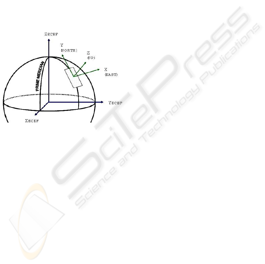
rf. In aeronautical notation 3D rotations are usually
parameterized using the YXZ Euler-angles represen-
tation, which factorizes the attitude rotation as a se-
quence of three rotations about the coordinate axis:
R
ENU→AHRS
(α, β, γ) = R
Y
(α)R
X
(β)R
Z
(γ) , where
(γ, β, α) are denoted as Heading, Pitch and Roll re-
spectively (Fig.1).
Figure 1: A plane tangent to the hypothetical spheroid sur-
face contains the local East North directions, which set
those axis for the East-North-Up reference frame.
Let us assume we are given a camera rigidly attached
to an AHRS, so that we can express the camera atti-
tude as a composition of a two rotations:
R
ENU→Cam
= R
AHRS→Cam
R
ENU→AHRS
. (1)
Our objective is to estimate R
AHRS→Cam
, which rep-
resents the unknown in the previous relation. Such a
rotation could be easily estimated from a set of N pairs
of corresponding vectors V = {v
AHRS
i
, v
Cam
i
}
i=1..N
,
where any pair represents the same direction in 3D
space, expressed as vector in the AHRS and in the
camera rf. respectively. Once the set V is known, the
rotation R
AHRS→Cam
is simply given by the solution
to the minimization problem:
R
AHRS→Cam
= min
R ∈SO(3)
∑
i
v
Cam
i
− R v
AHRS
i
2
. (2)
This is a classical problem of rotation fitting, widely
studied in literature, which can be solved using sev-
eral different methods. In this work we used the
approach based on the Singular Value Decomposi-
tion (SVD), described in (Kanatani, 1994). What is
needed is a procedure to build the set V, identifying
those 3D directions which may be estimated in a reli-
able way both in the camera and the AHRS rf. The so-
lution proposed in (Lobo and Dias, 2003; Alves et al.,
2003; Lobo and Dias, 2007) and revisited in this pa-
per, involves the exploitation of the vertical direction,
denoted for clarity by the vector UP
ENU
= [0, 0, 1]
T
.
In the original paper the authors used the projection
of scene vertical lines, retrieved from a calibration
checkerboardplaced vertically. We notice that this ap-
proach may result in a poor estimation due to the nu-
merical instability of vanishing points measurement
and to the difficulty to reach a high accuracy in the
positioning of the calibration object. Instead, we ob-
serve that the vertical direction can be represented by
any object hanging by a thread, only undergoing ac-
tion of gravity. Therefore, as an alternative solution
we propose to use different geometrical entities in-
ferred from the projectivegeometry of single axis mo-
tions, which can be robustly estimated from the tracks
left on the image plane during the object revolution
motion.
The full procedure is performed into two main
steps. In the first one we build the set V by iterat-
ing a basic processing unit which is performed with
fixed acquisition system and rotating calibration ob-
ject. Any iteration is performed with different orien-
tation of the acquisition system and provides a pair
of corresponding vectors (UP
Cam
, UP
AHRS
). The vec-
tor UP
Cam
is computed from the different geometri-
cal entities inferred by the assumption of single axis
motion (two different technique will be presented),
while UP
AHRS
is trivially given by the third column
of the AHRS orientation matrix R
ENU→AHRS
, directly
computed from the attitude angles Heading, Pitch and
Roll. The second step is the SVD-based estimation
of the rotation best describing the transformation be-
tween the vectors sets.
It is worth to underlinethat the pose of the camera-
AHRS system is not changed during one iteration of
the calibration procedure, then the orientation mea-
surement provided by the AHRS is constant up to
an additive noise, assumed approximately white zero
mean Gaussian. Under this assumption the Maximum
Likelihood estimation of R
ENU→AHRS
is simply ob-
tained by averaging the set of the collected orienta-
tion matrices. The averaging operation over the group
SO(3) is perfomed by means of the QR decomposi-
tion, as described in (Moakher, 2002).
VISAPP 2009 - International Conference on Computer Vision Theory and Applications
14
−0.5
0
0.5
−0.5
0
0.5
−0.8
−0.6
−0.4
−0.2
0
0.2
0.4
0.6
0.8
UP
Cam
Y
Z
X
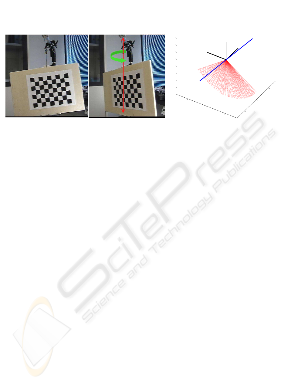
Figure 2: The two frames on the left show the rotation of the calibration planar object about the vertical direction, used as
basic calibration step. The plot on the right shows an example of vertical direction estimation in camera reference frame,
using the horizontal plane spanned by the vector Z
Cam
, normal to the calibration object, during one single-axis motion. In
blue is drawn the vector UP
Cam
estimated by linear regression.
3 CALIBRATION FROM PLANAR
HOMOGRAPHY
The first proposed technique uses as calibration tool a
planar checkerboard hung down a fixed point through
a thread. The object undergoes a rotation around the
vertical axis by applying a small twisting to the thread
(Fig. 2).
It is well know that the perspective projection of a
3D plane Π onto an image, is described by a homog-
raphy. If we introduce a rf. Ob j, aligned to Π with the
Z-axis parallel to the plane normal, then the equation
of Π is given by Z = 0 and the homography from the
plane Π to the image plane factorizes as:
H
Obj→Cam
= [r
1
|r
2
|T
Cam
], (3)
where r
1
and r
2
are the first two columns of the ma-
trix R
Obj→Cam
which describes the relative orienta-
tion between the camera and the rf. Obj, T
Cam
is the
translation vector expressed in the camera rf. (Zhang,
2000). Under the camera rigid motion, the Z-axis
(normal to Π) transforms as:
Z
Cam
= R
Obj→Cam
[0, 0, 1]
T
= r
3
= [r
1
]
×
r
2
(4)
where [·]
×
is the skew symmetric matrix equivalent
to the cross product operation. Therefore from the
planar homography (3) one can easily determine the
vector Z
Cam
. Since the planar object undergoes ro-
tation motion around the vertical axis, we can gather
that during such a motion the vector Z
Cam
spans the
horizontal plane. Therefore the sequence of homo-
graphies {H
Obj→Cam
i
}
i=1...M
computed during the ob-
ject rotation, will provides by factorization the set of
vectors lying on the horizontal plane {Z
Cam
i
}
i=1...M
,
where M is the number of images collected during the
object revolution. Then the vertical direction UP
Cam
,
assumed fixed during the object motion, is estimated
by linear fitting as the solution to the minimization
problem (Fig. 2):
UP
Cam
= min
v∈R
3
M
∑
j=1
|v
T
Z
Cam
j
|
2
. (5)
4 CALIBRATION FROM
CIRCULAR POINTS
In the previous section we proposed a technique to
estimate the vector UP
Cam
from a sequence of pla-
nar homographies, obtained during the rotation of a
known planar calibration object. We now present a
slightly more uncalibrated approach which does not
require any a-priori known planar object, but keeps
only the assumption of single axis motion around the
vertical axis.
Let’s define a virtual rf. Obj, aligned with the Z axis
parallel to the vertical direction and the X − Y axis
spanning the horizontal plane Π. On the projective
plane Π the line at infinity l
Obj
∞
∼ [0, 0, 1]
T
is trans-
formed by the projectivity (3) in the corresponding
vanishing line l
Cam
∞
, in the image space :
l
Cam
∞
∼
H
Obj→Cam
−T
l
Obj
∞
. (6)
By substituting the structure of the planar homogra-
phy (3) in the relation
H
Obj→Cam
T
H
Obj→Cam
−T
= I
3×3
, one can de-
duce that then the third column of
H
Obj→Cam
−T
must be the orthogonal to both r
1
and r
2
. We can
then parameterize the line-projectivity as:
H
Obj→Cam
−T
∼ [a|b|r
3
]. (7)
ESTIMATION OF INERTIAL SENSOR TO CAMERA ROTATION FROM SINGLE AXIS MOTION
15
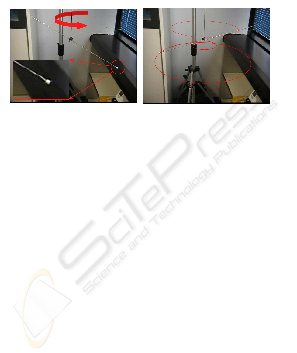
Figure 3: Simple 1D calibration tool. Notice that in principle any object with unknown geometry could be used, since the
technique relies only on feature tracks. On the right are shown the three ellipses fitted from the tracked features.
for some a,b∈ R
3
which can be left undetermined for
our purposes. By substituting (7) in the equation (6)
we obtain:
l
Cam
∞
∼ r
3
= UP
Cam
. (8)
Notice that r
3
is the representation of the vertical di-
rection in the camera rf., therefore the identification
in the image plane of the vanishing line l
Cam
∞
corre-
sponding to the 3D horizontal plane, directly gives the
metric measure of the vector UP
Cam
. We will estimate
the homogeneousvector representing the line l
Cam
∞
, by
searching the images of the Circular Points.
Let P ∈ R
3
be a 3D point undergoing circular
motion around the vertical axis: necessarily P will
describe a circular trajectory laying on a horizontal
plane. To this curve belong two complex points, de-
noted as Circular Points (CPs) due to the fact that they
also lie on any circle in the projective plane (Hart-
ley and Zisserman, 2004). The CPs are expressed in
2D homogeneouscoordinates by J
Obj
0
∼ [1, i, 0]
T
and
J
Obj
1
∼
J
Obj
0
∗
, where the notation (·)
∗
means com-
plex conjugate. By direct inspection of the circular
points coordinates, one can easily see that they also
belong to the line at infinity identified by the inter-
section of Π with the plane at infinity. In 3D pro-
jective space they actually represent the intersections
of any circle lying on any plane parallel to Π with
the plane at infinity. This property holds under any
arbitrary projective transformation and therefore the
images of all the 3D circles lying in the 3D space in
some plane parallel to Π, will have a common pair of
complex points, given by the images of the circular
points, J
Cam
0
and J
Cam
1
. As in 3D space, they also be-
long to the vanishing line l
Cam
∞
(our objective), which
therefore can be estimated as:
l
Cam
∞
∼ [J
Cam
0
]
×
J
Cam
1
= [J
Cam
0
]
×
J
Cam
0
∗
. (9)
As we pointed out the circular points lie on all cir-
cles in the projective plane, therefore their images
J
Cam
0
, J
Cam
1
, can be estimated as the intersection of
the images of at least three horizontal circles. In our
calibration framework these curves are actually el-
lipses, since we assumed that the 3D circles virtually
drawn in the space by the rotating object, are fully
contained in the camera semi space z > 0, i.e. they are
not (even partially) behind the camera. As stated by
the Bezout Theorem any two ellipses in the 2D pro-
jective space have four intersection points. Given that
the two ellipses are the projection of concentric cir-
cles lying on parallel planes in 3D, we can infer that at
least two of them are complexconjugate and represent
the images of the circular points. An indeterminacy
raise when two ellipses do not intersect on real points
but on two pairs of complex conjugate points. In this
case it not possible to discriminate between the two
pairs in order to choose the points
J
Cam
0
, J
Cam
1
. Such
an indeterminacy can be removed simply searching
for the common points among three (instead of just
two) ellipses in the image plane. This is the reason
why we claimed that the images of three parallel cir-
cles are actually needed.
A simple tool like the one shown in Fig. 3 is an
example of an object which can be used in the calibra-
tion procedure to draw horizontal circles in 3D space,
in substitution of the planar checkerboard used in the
previous section. Notice this is just a possible solu-
tion, appealing because the white dots on the rod can
be easily tracked in the video sequence, but in princi-
ple any unknown object could be used, since the tech-
nique is based on conic fitting from any feature track.
Once the three conics are estimated the intersection
points are pair-wise computed. We expect that a pair
of complex conjugate points appear in both the two
VISAPP 2009 - International Conference on Computer Vision Theory and Applications
16
0 0.5 1 1.5 2 2.5 3 3.5 4 4.5 5
0
0.2
0.4
0.6
0.8
1
1.2
1.4
1.6
1.8
2
σ
n
θ
e
[deg]
0 0.5 1 1.5 2 2.5 3 3.5 4 4.5 5
0
0.2
0.4
0.6
0.8
1
1.2
1.4
1.6
1.8
2
σ
n
θ
e
[deg]
0 0.5 1 1.5 2 2.5 3 3.5 4 4.5 5
0
0.2
0.4
0.6
0.8
1
1.2
1.4
1.6
1.8
2
σ
n
θ
e
[deg]
0 0.5 1 1.5 2 2.5 3 3.5 4 4.5 5
0
0.2
0.4
0.6
0.8
1
1.2
1.4
1.6
1.8
2
σ
n
θ
e
[deg]
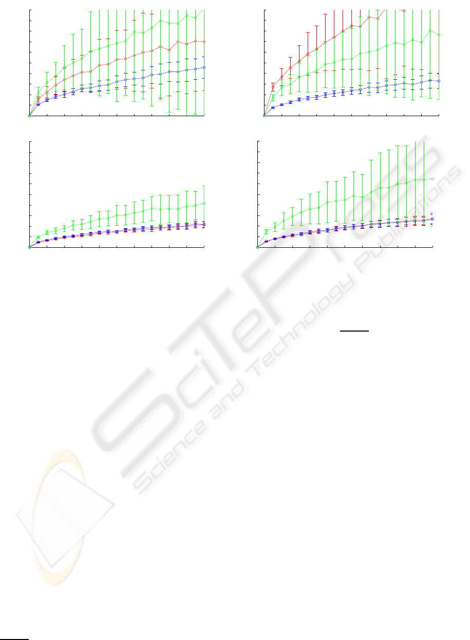
Figure 4: Result obtained on simulated data. The plots show the mean value and variance of the estimation error (10) for
increasing value of the additive Gaussian noise corrupting the image point coordinates. The line colors are used to discriminate
among the three evaluated techniques: the blu line for planar homography, the red line for the conic fitting and the green line
for the vanishing points respectively.
sets of intersections, then we choose the point closest
to the two set as the image J
Cam
0
of one circular point.
Finally from (9) we can estimate the rotation axis, i.e.
the vertical direction UP
Cam
.
5 RESULTS
A wide series of tests has been carried out on sim-
ulated data in order to evaluate the performance of
the algorithms described in section 3 and 4, compared
with the technique based on vanishing points (Alves
et al., 2003). In each test the synthetic camera ori-
entation is slightly modified by an additional rotation
randomly selected in the neighbourhood of the iden-
tity matrix and the image points are corrupted by ad-
ditive Gaussian noise: the basic block of tests collects
five hundreds of these trials. Twenty test-blocks have
been carried out with increasing variance of the ad-
ditive Gaussian noise. This complete sequence has
been repeated for four different camera locations, in
order to evaluate the capability of algorithms to cope
with viewing slant with respect to the calibration ob-
ject. The estimation error has been defined in terms of
angular distance between the real vertical direction,
UP
Cam
and the estimated one, UP
Cam
:
θ
e
= cos
−1
UP
Cam
T
UP
Cam
. (10)
The results from the three evaluated techniques are
presented in Fig.4.
In order to provide a fair comparison the three
techniques have been tested in their linear form. The
final calibration module implements the technique
presenting the best performance as initialization for
a non linear refinement step, based on the Levenberg-
Marquardt iterative algorithm to minimize the corre-
sponding geometric error.
It is evident that the approach based on planar ho-
mography guarantees the best performance and there-
fore has been selected for calibrating real sensors.
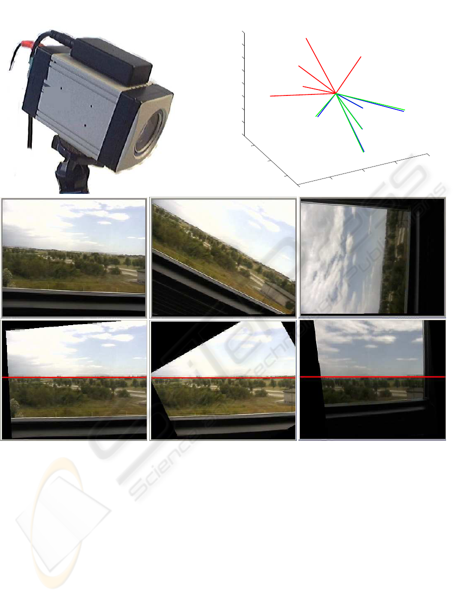
The employed system is composed by a low cost in-
ertial sensor rigidly attached to a (768 X 576) ana-
log camera (Fig.4.c). The quality of the estimated
relative orientation between the camera and inertial
sensors (Fig.5), is evaluated by computing the mean
value of the reprojection error between the two sets of
estimated vectors (0.6422
◦
) and its variance (0.2217).
6 CONCLUSIONS
A framework to estimate the relative orientation be-
tween an inertial sensor and a camera by using the
ESTIMATION OF INERTIAL SENSOR TO CAMERA ROTATION FROM SINGLE AXIS MOTION
17
(a)
−1
−0.5
0
0.5
1
−0.5
0
0.5
−0.8
−0.6
−0.4
−0.2
0
0.2
0.4
0.6
0.8
1.3694
0.35916
0.30095
0.31158
0.87006
(b)
Figure 5: Calibration results on real acquisition system. (a) On the left the system composed by the camera and the rigidly
attached AHRS. On the right (b) the calibration directions obtained from five different sequences, presented as a set of vectors
pairs V = {UP
AHRS
i
, UP
C
i
am}
i=1..5
. The red and blue lines are the vectors expressed in the AHRS r.f. and in the camera
r.f. respectively. In green are drawn the rotated vectors R
AHRS→Cam
UP
AHRS
i
, obtained by using the estimated rotation, with
the indication of the angular error expressed in degrees. The last two rows present an application of the technique for video
stabilization: the first three images are raw frames selected from a video sequence, the last row presents the same frames
stabilized in Pitch and Roll.
projective geometry of revolution motions about the
vertical axis, has been presented. The main contri-
bution of this work is provided by the exploitation of
conics and planar homographies for the estimation of
the vertical direction in the camera rf., which playes
a central role for the camera attitude estimation. The
choice of these geometrical entities is supported by
the stability of the numerical fitting algorithms, which
can cope with severeslant between the camera and the
calibration structure. In the paper we have been pre-
sented results on simulated as well as real data, which
showed that among the three compared approaches,
the planar homography is the geometrical entity best
fitting this sort of problems.
REFERENCES
Alves, J., Lobo, J., and Dias, J. (2003). Camera-inertial
sensor modelling and alignment for visual navigation.
VISAPP 2009 - International Conference on Computer Vision Theory and Applications
18

In 11th Int. Conference on Advenced Robotics, pages
1693–1698.
Catala, P. A., Rataj, J., and Reulke, R. (2006). Self-
calibration system forthe orientation of a vehicle cam-
era. International Archives of Photogrammetry and
Remote Sensing, XXXVI(5):68 – 73.
Hartley, R. and Zisserman, A. (2004). Multiple View Geom-
etry in Computer Vision. Cambridge University Press,
ISBN: 0521540518, second edition.
Jang, J. S. and Liccardo, D. (2007). Small uav automation
using mems. IEEE Aerospace and Electronic Systems
Magazine, 22(5):30–34.
Kanatani, K. (1994). Analysis of 3-d rotation fitting. IEEE
Trans. Pattern Anal. Mach. Intell., 16(5):543–549.
Kim, J. and Sukkarieh, S. (2004). Autonomous air-
borne navigation in unknown terrain environments.
Aerospace and Electronic Systems, IEEE Transac-
tions on, 40(3):1031–1045.
Lobo, J. and Dias, J. (2003). Vision and inertial sensor co-
operation using gravity as a vertical reference. IEEE
Trans. Pattern Anal. Mach. Intell., 25(12):1597–1608.
Lobo, J. and Dias, J. (2004). Inertial sensed ego-motion for
3d vision. J. Robot. Syst., 21(1):3–12.
Lobo, J. and Dias, J. (2007). Relative pose calibration be-
tween visual and inertial sensors. Int. J. Rob. Res.,
26(6):561–575.
Merino, L. and al (2006). Vision-based multi-uav posi-
tion estimation. Robotics and Automation Magazine,
IEEE, 13(3):53–62.
Moakher, M. (2002). Means and averaging in the group
of rotations. SIAM Journal on Matrix Analysis and
Applications, 24(1):1–16.
Templeton, T., Shim, D. H., Geyer, C., and Sastry, S.
(2007). Autonomous vision-based landing and ter-
rain mapping using an mpc-controlled unmanned ro-
torcraft. In Robotics and Automation, 2007 IEEE In-
ternational Conference on, pages 1349–1356.
Zhang, Z. (2000). A flexible new technique for camera
calibration. IEEE Trans. Pattern Anal. Mach. Intell.,
22(11):1330–1334.
ESTIMATION OF INERTIAL SENSOR TO CAMERA ROTATION FROM SINGLE AXIS MOTION
19
