
DATA MINING APPROACH FOR POSITIONING CAMERA IN
DISPLAYING MOCAP SEARCH RESULTS
Sindharta Tanuwijaya and Yoshio Ohno
Department of Information and Computer Science, Keio University, 3-14-1 Hiyoshi Kohoku, Yokohama, Japan
Keywords:
Motion capture, Mocap, Camera.
Abstract:
In recent years, the amount of mocap has accumulated due to its popularity in creating realistic human mo-
tions. However, such accumulation is yet to be accompanied by the development of a mocap search engine.
In addition to the difficulty in processing mocap search, this phenomenon is also due to the problems in dis-
playing mocap as search results, one of which is determining the camera position, orientation, and distance
in displaying mocap. In this paper, we specify camera orientation and distance as constraints to determine
camera positions by using available training data which are given as inputs into data mining techniques. In
addition, we also discuss a method to select representative frames of mocap, thus allowing for the display of
mocap search results as a list of sets of selected mocap frames. Finally, we employ a number of data mining
techniques along with a simple method to determine the camera position which yields the widest projection
area of a virtual face consisting hands and feet joints into the camera plane, and compare the results to each
other.
1 INTRODUCTION
The capability to search motion capture data, com-
monly abbreviated as mocap, has become more im-
portant as the amount of mocap has accumulated due
to its popularity in creating realistic human motion
since around two decades ago. But although several
methods to search mocap have been proposed (Forbes
and Fiume, 2005), (Liu et al., 2005), (Chiu et al.,
2004), (Cardle et al., 2003), a search engine to search
mocap, which must also consider how to best display
the search results, is still yet to be established.
One of the reasons of this phenomenon is the diffi-
culty in displaying the mocap frames, which describes
a number of joints moving in spacetime, in a format
that allows multiple mocap to be viewed simultane-
ously as search results, such as a list in case of text
documents (Google, 2008), (Yahoo, 2008). Display-
ing all frames of mocap search results or playing them
as videos simultaneously is much likely to cause data
overload and confuse users, even if they are short.
Playing a short animation if necessary, for example if
the mouse cursor is over an image of one search result,
is an appealing idea, but users can not see the motion
at first glance and have to move the mouse cursor over
each mocap search result, which will become tedious
in a short time. In addition, it is not a trivial problem
to determine from which angle the motions have to be
rendered, or in other words, there is another problem
of determining the camera position, orientation, and
distance from the subject.
In this paper, we propose a data mining approach
to determine camera positions relative to the subject
in displaying mocap frames. To display the selected
frames of one mocap, we opt for side by side view as
shown in Figure 1, in which there are several images
depicting different frames of one mocap, and the im-
ages are arranged in a row. In addition to the inexpen-
sive computation, we believe that it shows the rela-
tionship of one frame to the other frames well enough,
and it does not take too much space on a user’s display
monitor. Conforming to the usual practice in display-
ing text documents, we can then display multiple mo-
cap search results as a list of sets of selected mocap
frames.
2 RELATED WORK
The problem to illustrate motion in still imagery was
first stated by (Assa et al., 2005), in which the author
proposed a method to automatically select key poses
from motion capture. Additionally, the paper also de-
scribed the problem of illustrating the motion. Usu-
266
Tanuwijaya S. and Ohno Y. (2009).
DATA MINING APPROACH FOR POSITIONING CAMERA IN DISPLAYING MOCAP SEARCH RESULTS.
In Proceedings of the Fourth International Conference on Computer Graphics Theory and Applications, pages 266-273
DOI: 10.5220/0001769202660273
Copyright
c
SciTePress

ally, key poses are displayed as a set of images po-
sitioned side by side, while another approach called
digital strobing combines all the key poses into a sin-
gle image by sharing a common background. A novel
method called spatially extended layout was intro-
duced in the paper to address the drawbacks of dig-
ital strobing. However, in the paper, the author didn’t
mention the problem of determining camera positions
and orientations in displaying mocap frames.
It seems natural that the best viewpoint is the one
that obtains the maximum information of a scene.
(Roberts and Marshall, 1998) defined the best view
as the view which direction has the smallest angular
offset from the inverse surface normals of the faces
in the scene. (V
´
azquez et al., 2001) proposed another
approach by using the probability distribution of the
projected area over the sphere of directions centered
in the viewpoint, called viewpoint entropy, to measure
the maximum information of a scene, while (Stoev
and Strasser, 2002) argued that the above methods fail
to give a good overview of the scene’s depth such as
the scene of a landscape and extended the approach by
maximizing not only the projected area of the scene,
but also the depth of the scene.
(Bares and Lester, 1999) introduced partial con-
traints which are defined by system users through an
interface to determine the best camera position auto-
matically, while (Arbel and Ferrie, 1999) and (Marc-
hand and Courty, 2000) addressed the problem of gen-
erating camera trajectories automatically based on the
current view.
Some of the rules applied in the film domain have
also been surveyed. (Drucker and Zeltzer, 1995) en-
capsulated several constraints based on the rules into
a camera module, which can be connected to another
camera module for transition. Using a similar con-
cept, (He et al., 1996) introduced film idioms, a hier-
archical finite state machine to determine transitions,
while the idioms determine which camera modules
should be used in a particular state. Another approach
(David B. Christianson, 1996) described Declarative
Camera Control Language (DCCL) to encode the
rules found in the film domain.
While we generally agree that the best view
should have the maximum information of the corre-
sponding scene, in displaying mocap, it is usually not
the projected area of the joints or bones that have to be
considered, but rather the motion itself which involves
multiple joints moving in spacetime. Further, mocap
itself naturally has no faces since it contains only the
coordinates of the joints. One may be tempted to cre-
ate a virtual face by connecting both hand joints and
feet joints, and then determine the view which will
produce the widest projection area of the virtual face
into the camera plane, but such an approach fails to
address the fundamental issue of looking for the view
that best conveys the motion itself. For example rather
than the general view which is able to display all the
joints clearly, we are naturally more interested in the
movement of the leg joints in more detail when look-
ing at a kicking motion.
The rules from the film domain cannot also be
straightforwardly applied to the problem since instead
of looking for ways to move the camera, our goal
is to determine camera positions in displaying mo-
cap frames. There are however several basic rules
that can be applied, such as the possible locations of
the camera (internal, parallel, external), and the dis-
tance of the camera with respect to the subject (ex-
treme, closeup, medium, full, long). In fact, almost
all the previous approaches described above refer to
the use of positions located on the surface of a virtual
sphere surrounding the subject as candidates for the
best camera position, which are usually represented
as spherical coordinates.
As also pointed out by (Stoev and Strasser, 2002),
we believe that until now, there are no objective mea-
surements and criteria for evaluating the goodness of
camera positions, especially in the case of display-
ing mocap. Therefore, we propose a novel approach
to determine the best camera position relative to the
subject by using a data mining approach. The use of
data mining for camera transition in computer graph-
ics community was first explored by (Singh and Bal-
akrishnan, 2004) to generate non-linear projection of
a 3d scene.
3 APPROACH
3.1 Overview
Displaying all frames of the mocap will cause in-
formation overload, no matter from which angle the
frames are rendered. Therefore, in the next subsec-
tion, we will first describe our simple method to select
the frames of one mocap. After that, we will describe
what attributes that we choose in building data mining
classifiers, or specifically the attributes of the joints,
which are used as input attributes, and the attributes
of the camera, which are used as the output or target
attributes of the classifiers. We stress in this section
that we are not concerned with discovering novel data
mining techniques, but rather, we seek to apply es-
tablished data mining techniques to a new problem
domain.
DATA MINING APPROACH FOR POSITIONING CAMERA IN DISPLAYING MOCAP SEARCH RESULTS
267
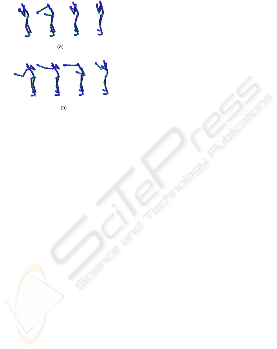
Figure 1: Selecting Frames: (a) uniform sampling, (b) our
method.
3.2 Selecting Frames
We regard k as the number of frames for one mocap
that are going to be displayed. Initially, the mean of
the joint positions of all frames in the mocap is cal-
culated to be used as the center point. Then, we de-
termine the first selected frame as the frame which
has the longest distance to the center point. At the
next iteration, the second selected frame is defined
to be the frame which has the longest distance to the
center point and to the the nearest previously selected
frames. These steps are repeated until the number of
selected frames reaches k. The value of k itself can be
defined as the number of frames required to represent
one mocap, or in other words a constant. Another op-
tion is to set k based on the length or other statistical
values of the mocap.
Since these selected frames basically represent ex-
treme body poses which have the longest distances
from other body poses in the motion, we are con-
vinced that they will represent the motion better than
taking uniformly spaced k frames from the motion as
can be seen in Figure 1. When users look at such
multiple extreme poses at the same time, it is rela-
tively easy to visualize inbetween poses among them
although these inbetween poses are actually not dis-
played. Similarly, it is difficult, if not impossible, to
visualize the extreme body poses when only the inbe-
tween poses are shown to users.
3.3 Joint Attributes
For displaying a selected frame, we believe that the
best camera position depends on the body pose in that
frame, which can be roughly estimated by the direc-
tion of the joints of the body. The concept of repre-
senting body poses using the direction of joints is very
similar to Labanotation score (Hutchinson, 1977), a
dance notation which uses symbols to define the di-
rection of movement among other things. Undoubt-
edly, the use of Labanotation in computer graphics
community is not new (Hachimura and Nakamura,
2001), (Yu et al., 2005), (Shen et al., 2005).
In a simple Labanotation score, there can be 27
possible directions for each joint, which are repre-
sented by nine horizontal direction symbols and three
vertical direction symbols. In order to address the
need in data mining that similar directions should
have small distances, we utilize three attributes: X-
axis, Y-axis, and Z-axis to represent the direction of
each joint, which are specified relative to the position
and orientation of the center of the subject, usually
called the root joint.
3.4 Camera Attributes
In determining the properties of the camera using
spherical coordinates, there are actually five variables
that have to be specified: the angle from the positive
y-axis centered on the subject to the camera position
(θ), the angle from the positive x-axis centered on the
subject to the orthogonal projection of the camera po-
sition on the X-Z plane (φ), the distance of the camera
from the subject, and two additional similar angles to
determine the orientation of the camera.
In this paper, we constrain the camera so that it al-
ways faces the root joint, and we also define a fixed
value to be the distance. This leaves only two vari-
ables: θ and φ to be determined. Unlike the joint at-
tributes, the values of these camera attributes cannot
be calculated directly based on the poses in the mo-
cap, and will be determined using data mining clas-
sifiers. That is, by building classifiers based on the
available training data, then, given the joint attributes
of new data, we can estimate their camera attributes.
3.5 Line of Interest
There is one established rule in cinematography,
called “don’t cross the line”, which is also referred to
by (He et al., 1996). This rule implies that once a shot
is taken from the left side of the line of interest as can
be seen in Figure 2, subsequent shots should also be
taken from the same side, and similarly if the first shot
is taken from the right side of the line of interest. This
rule leads us to reason that the same behavior should
also apply when displaying a list of multiple mocap
represented by several frames. In other words, if one
set of frames of mocap uses a camera positioned at its
GRAPP 2009 - International Conference on Computer Graphics Theory and Applications
268
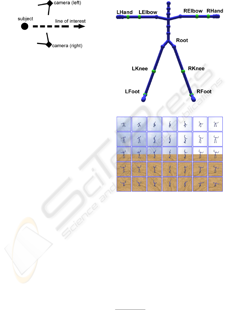
Figure 2: Line of interest and two cameras positioned on its
left and right side.
left side, then the other sets of frames of other mocap
must also use cameras positioned at their left sides.
3.6 Putting It All Together
To ensure consistencies among data, one of the two
camera angles: φ is specified relative to the orienta-
tion of the root joint, which means a value of zero
always indicates the front of the body pose. If φ is
not specified relative to the root orientation, two exact
motions with different root directions may have very
different φ values, causing inconsistencies in the data.
Then, the inputs to build the data mining classi-
fiers will form a matrix:
[ ja
i1
, .., ja
in
, phi
i
, theta
i
] (1)
where ja
i j
indicated the j-th joint attribute of the i-th
data, n indicates three (X, Y, Z axis) times the num-
ber of selected joints as described in the previous sub-
section, and phi
i
, theta
i
indicates the corresponding
camera angles for the i-th data.
4 IMPLEMENTATION
Most of our data come in the form of a skeletal hier-
archy of Euler joint angles (CMU, 2007). In select-
ing frames, we convert this representation into three
dimensional joint positions by ignoring the global X
and Z translation of the root joint because we choose
to regard XZ planar transformations of the root joint
as irrelevant in selecting the frames. Then, in deter-
mining joint attributes, we further calculate the direc-
tions of the eight selected joints as shown in Figure 3.
In total there will be 24 joint attributes.
4.1 Classifiers
To collect training data, we provide a set of images to
display a selected mocap frame using uniformly di-
vided θ and φ values and ask users to choose which
image that he or she thinks is the best in displaying
Figure 3: Selected joints.
Figure 4: Images for collecting training data.
that particular frame or pose as can be seen in Fig-
ure 4. There are only a couple of users participating
in this training data collection at the moment, includ-
ing the authors, but we have put the program to do
this process on the Internet
1
, allowing anyone around
the world to participate. For the results written in this
paper, we have managed to accumulate around two
hundred training data, and we build our data mining
classifiers based on this data.
Initially, we need two data mining classifiers. One
is used to determine θ, and one is used to determine
φ. Further, given the “line of interest” constraint de-
scribed in the previous section, we have a group of
four data mining classifiers, in which two of them are
used to determine θ and φ of the camera positioned at
the left side of the line of interest, and the other two
are used to determine the same angles of the camera
1
http://bebas.on.ics.keio.ac.jp
DATA MINING APPROACH FOR POSITIONING CAMERA IN DISPLAYING MOCAP SEARCH RESULTS
269
positioned at right side.
In our experiment however, from many available
data mining techniques, we also try to compare which
techniques are suitable for determining camera an-
gles. This leads to the creation of several groups,
each having four data mining classifiers as explained
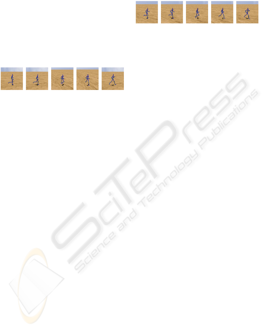
above. An example of the images of a running motion
produced by using the camera angles obtained from a
radial basis function network can be seen in Figure 5
Figure 5: Images of a running motion produced by a radial
basis function network classifier.
4.2 Weighting
Using the above approach, although the selected
frames of a single mocap are displayed using cam-
era positions at the same side of the line of interest,
it sometimes occurs that the camera angles (θ,φ) are
substantially different for the selected frames. This
phenomenon can be confusing for users if they are
not used to looking at subsequent images of the same
motion which are taken from different camera angles.
One simple approach to alleviate this problem is to
take the average of all the camera angles of the se-
lected frames, and use the average value to display all
the frames.
A better approach that we have implemented, is
by giving different weights to the camera angles of
each selected frames. As described in the previous
section, the first selected frame is the frame which
has the longest distance to the center point or to the
previously selected frames, which is none in this case.
The second selected frame is then the frame which has
the second longest distance and so on. Thus, giving
higher weight to earlier selected frames is appropri-
ate in the sense that the earliest selected frame is the
frame that can most distinguish the motion from other
motions.
Also, while using the orientation of root as the
base to calculate φ may cause a rotating motion rep-
resented by several frames to be indiscernible since
they may have the same local phi values relative to
the root, the practices of averaging or weighting will
cause the selected frames of a motion to be displayed
with the same global camera angles, and thus able
to solve such problems. The result of weighting the
camera angles can be seen in Figure 6.
Figure 6: A result of weighting camera angles.
5 DATA MINING TECHNIQUES
COMPARISON
We choose several data mining techniques from (Wit-
ten and Frank, 2005) which can estimate numeric data
as the value of camera angles are numeric. The data
mining techniques used in this paper are as follows:
widest projection, M5P model tree, backpropagation
neural network, reduced-error pruning tree, radial ba-
sis function network, and SMO for support vector re-
gression.
Additionally, we have also implemented a simple
method, which we call widest projection method, to
discover the camera angles which yield the widest
projection area of a virtual face consisting both two
hand points and two feet points into the camera plane.
The results of the widest projection method, along
with the results of the chosen data mining techniques,
are then evaluated by asking users from various back-
grounds to give scores ranging from 1 to 10 .
Specifically, we prepare a set of selected frames
from running, punching, soccer, basketball, and base-
ball mocap. A user gives his or her score for the
same number of images, in which each method is ap-
plied equally and we have accumulated more than two
thousand images evaluated by users for the purpose
of comparison. The evaluation of each technique and
each mocap group can be seen in Figure 7, in which
the vertical axis represents the average score given by
users for that particular technique and mocap group.
The figure shows that two of of the data mining ap-
proaches, in particular pruning tree and radial basis
function, generally yield better results than the other
methods.
6 DISCUSSION
We have introduced a simple method to select mo-
cap frames and have proposed the use established data
mining techniques in a new problem domain of de-
termining camera angles in order to display mocap
search results in a format such as a list. Other re-
sults can be seen in Figure 8, which also demonstrates
that our simple frame selection method works quite
well for motions including rolling motions. We inten-
GRAPP 2009 - International Conference on Computer Graphics Theory and Applications
270
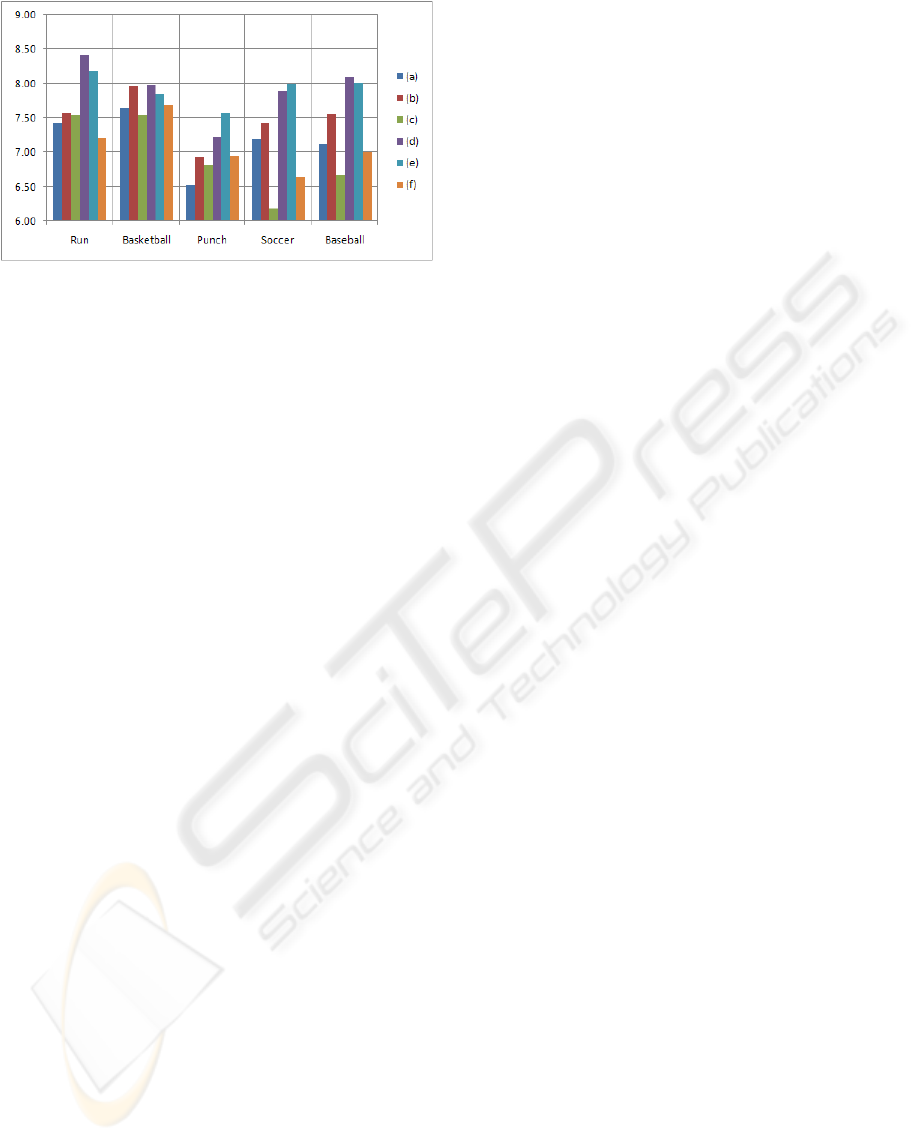
Figure 7: Techniques Comparison: (a) Widest projection.
(b) M5P model tree. (c) Backpropagation neural network.
(d) Reduced-error pruning tree. (e) Radial Basis Function
network. (f) SMO for support vector regression.
tionally provide non-weighted results in this figure to
show the chosen camera angles based on each frame,
which are not affected by other frames in the same
mocap. We believe that this will allow better under-
standing of the results of the method described in this
paper.
Although we admit that our approach largely de-
pends on the training data, or input from users, we
have shown that two of the classifiers built by our cur-
rent limited training data are able to determine satis-
factory camera angles, indicated by the relatively high
scores given by users. Thus, we conclude that in gen-
eral, data mining techniques have the potential to es-
timate camera angles better than fixing the camera to
be positioned at a certain distance from the object, and
better than the widest projection method described in
the previous subsection. However, further research
would be required to determine whether the same sit-
uation applies for other types of motion which are not
included in this work.
It has to be noted that other than the chosen joint
attributes, our current approach does not take the cat-
egory or the type of the motion into consideration. We
believe that increasing the number of input attributes
other than joint attributes, and adding more training
data will allow for even better determination of cam-
era angles.
In the future, we are planning to give motion cues
to the selected frames to better illustrate the motion
such as the approach described in (Bouvier-Zappa
et al., 2007). Such an approach will further allow
the users to understand the performed motion by just
looking at several selected frames without looking at
the whole motion. For displaying exaggerated mo-
tions, it may also be interesting to emphasize view-
able parts of the body from the determined camera
positions as described in (Singh and Balakrishnan,
2004)
ACKNOWLEDGEMENTS
The data used in this project was obtained from mo-
cap.cs.cmu.edu. The authors would also like to thank
all of the people who have participated in the surveys.
REFERENCES
Arbel, T. and Ferrie, F. (1999). Viewpoint selection by nav-
igation through entropy maps. pages 248–254.
Assa, J., Caspi, Y., and Cohen-Or, D. (2005). Action syn-
opsis: pose selection and illustration. ACM Trans.
Graph., 24(3):667–676.
Bares, W. H. and Lester, J. C. (1999). Intelligent multi-
shot visualization interfaces for dynamic 3d worlds.
In IUI ’99: Proceedings of the 4th international con-
ference on Intelligent user interfaces, pages 119–126,
New York, NY, USA. ACM.
Bouvier-Zappa, S., Ostromoukhov, V., and Poulin, P.
(2007). Motion cues for illustration of skeletal motion
capture data. In NPAR ’07: Proceedings of the 5th in-
ternational symposium on Non-photorealistic anima-
tion and rendering, pages 133–140, New York, NY,
USA. ACM.
Cardle, M., Vlachos, M., Brooks, S., Keogh, E., and
Gunopulos, D. (2003). Fast motion capture matching
with replicated motion editing. Proceedings of SIG-
GRAPH 2003 - Sketches and Applications.
Chiu, C., Chao, S., Wu, M., Yang, S., and Lin, H.
(2004). Content-based retrieval for human motion
data. 15(3):446–466.
CMU (2007). CMU graphics lab motion cap-
ture database. Retrieved November 2007, from
http://mocap.cs.cmu.edu/.
David B. Christianson, Sean E. Anderson, L.-w. H. D. H. S.
D. S. W. M. F. C. (1996). Declarative camera control
for automatic cinematography. unknown.
Drucker, S. M. and Zeltzer, D. (1995). Camdroid: a sys-
tem for implementing intelligent camera control. In
SI3D ’95: Proceedings of the 1995 symposium on In-
teractive 3D graphics, pages 139–144, New York, NY,
USA. ACM.
Forbes, K. and Fiume, E. (2005). An efficient search
algorithm for motion data using weighted pca. In
SCA ’05: Proceedings of the 2005 ACM SIG-
GRAPH/Eurographics Symposium on Computer An-
imation, pages 67–76, New York, NY, USA. ACM.
Google (2008). Google search.
Hachimura, K. and Nakamura, M. (2001). Method of gen-
erating coded description of human body motion from
motion-captured data. In Robot and Human Interac-
tive Communication, 2001. Proceedings. 10th IEEE
International Workshop, pages 122–127, Bordeaux,
Paris, France.
He, L., Cohen, M. F., and Salesin, D. H. (1996). The vir-
tual cinematographer: a paradigm for automatic real-
time camera control and directing. In SIGGRAPH ’96:
DATA MINING APPROACH FOR POSITIONING CAMERA IN DISPLAYING MOCAP SEARCH RESULTS
271

Proceedings of the 23rd annual conference on Com-
puter graphics and interactive techniques, pages 217–
224, New York, NY, USA. ACM.
Hutchinson, A. (1977). Labanotation. Theatre Arts Books.
Liu, G., Zhang, J., Wang, W., and McMillan, L. (2005).
A system for analyzing and indexing human-motion
databases. In SIGMOD ’05: Proceedings of the 2005
ACM SIGMOD international conference on Manage-
ment of data, pages 924–926, New York, NY, USA.
ACM.
Marchand, E. and Courty, N. (2000). Image-based vir-
tual camera motion strategies. In Graphics Interface,
pages 69–76.
Roberts, D. and Marshall, A. (1998). Viewpoint selection
for complete surface coverage of three dimensional
objects.
Shen, X., Li, Q., Yu, T., Geng, W., and Lau, N. (2005).
Mocap data editing via movement notations. In CAD-
CG ’05: Proceedings of the Ninth International Con-
ference on Computer Aided Design and Computer
Graphics, pages 463–470, Washington, DC, USA.
IEEE Computer Society.
Singh, K. and Balakrishnan, R. (2004). Visualizing 3d
scenes using non-linear projections and data mining
of previous camera movements. In AFRIGRAPH ’04:
Proceedings of the 3rd international conference on
Computer graphics, virtual reality, visualisation and
interaction in Africa, pages 41–48, New York, NY,
USA. ACM.
Stoev, S. L. and Strasser, W. (2002). A case study on au-
tomatic camera placement and motion for visualizing
historical data. In VIS ’02: Proceedings of the confer-
ence on Visualization ’02, pages 545–548, Washing-
ton, DC, USA. IEEE Computer Society.
V
´
azquez, P.-P., Feixas, M., Sbert, M., and Heidrich, W.
(2001). Viewpoint selection using viewpoint entropy.
In VMV ’01: Proceedings of the Vision Modeling and
Visualization Conference 2001, pages 273–280. Aka
GmbH.
Witten, I. H. and Frank, E. (2005). Data Mining: Practical
machine learning tools and techniques, 2nd Edition.
Morgan Kaufmann.
Yahoo (2008). Yahoo search.
Yu, T., Shen, X., Li, Q., and Geng, W. (2005). Motion re-
trieval based on movement notation language: Motion
capture and retrieval. Comput. Animat. Virtual Worlds,
16(3-4):273–282.
GRAPP 2009 - International Conference on Computer Graphics Theory and Applications
272
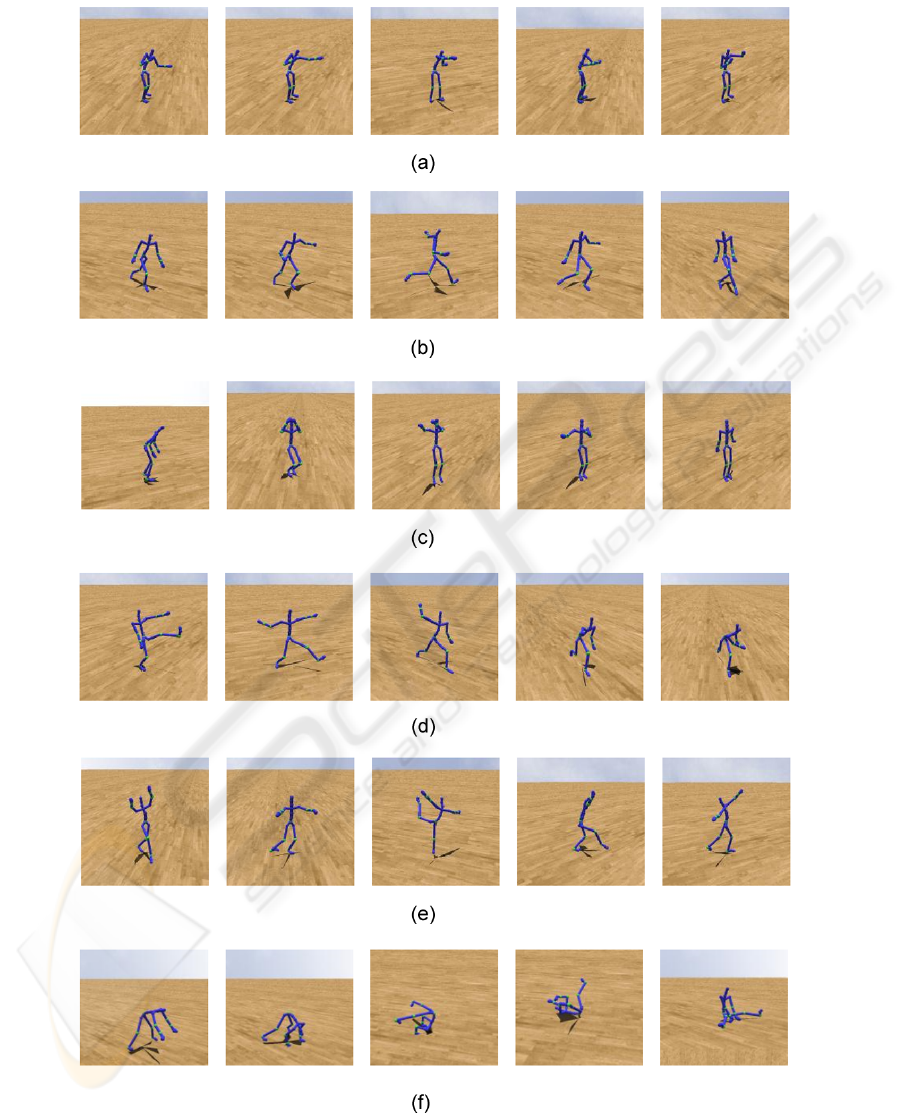
Figure 8: Other results by a radial basis function network classifier. (a) Punch. (b) Soccer kick. (c) Basketball jump shot. (d)
Baseball pitch. (e) Dance. (f) Rolling.
DATA MINING APPROACH FOR POSITIONING CAMERA IN DISPLAYING MOCAP SEARCH RESULTS
273
