
AN EFFICIENT UNDO/REDO-FRAMEWORK FOR
THREE-DIMENSIONAL VISUAL SIMULATION
OF ALGORITHMS AND DATA STRUCTURES
Ashraf Abu Baker
Institute of Computer Graphics, Department of Computer Science and Mathematics
Johann Wolfgang Goethe University, Frankfurt, Robert-Mayer-Str. 10, 60054 Frankfurt, Germany
Keywords:
Visual Siumlations, Three-dimensional algorithm animation, Undo/redo.
Abstract:
In order to be pedagogically effective, an algorithm visualisation is expected to satisfy a large number of
requirements. One of the most essential and useful requirements is its ability to provide support for reversing
performed user actions. In this work we will introduce a generic concept for an efficient undo/redo framework
for three-dimensional visual simulations of algorithms and data structures. The framework uses the memento
design pattern to implement a linear multiple-undo/multiple-action model with an unlimited undo of performed
actions. It is straightforward to utilise and supports the automated generation of three-dimensional visual
simulations of algorithms and data structures.
1 INTRODUCTION AND
MOTIVATION
Algorithm visualisation technology are gaining more
and more recognition as effective modern e-learning
and e-teaching instruments. With the recent in-
creasing popularity of algorithm visualisations, the
demands for effective algorithm visualisation tech-
niques have also increased. To be pedagogically ef-
fective an algorithm visualisation (AV) is expected
to satisfy a large number of essential requirements
(Roessling, 2002). Perhaps one of the most funda-
mental and useful features, which considerably af-
fects the effectiveness of a visualisation, is its abil-
ity to support reversing (undo) and redoing of user
actions (J. Archer and Schneider, 1984). Algorithm
visualisations that do not maintain this feature have
proven to be ineffective (Stasko and Badre, 1993).
Furthermore, studies on the pedagogical impact of
AV, demand that an AV should allow the user a wide
range of interactions, which enables him to freely ex-
plore all aspects of the visualised algorithm or data
structure (T. Naps and et al., 2003). Obviously, there
is a high correlation between the supported interac-
tion level and the number of features provided, on
the one hand, and the complexity of the implemen-
tation of an undo/redo mechanism on the other hand.
The more powerful a visualisation is, in terms of sup-
porting interactions and features, the more actions
need to be undone, and hence the higher is the ef-
fort required to implement an undo/redo facility. Ap-
parently, developing and implementing an efficient
generic undo/redo model for highly effective visual-
isations is not only essential but also difficult. Tak-
ing part in an annual internship at our Institute of
Computer Graphics, 19 students were required to de-
velop 38 three-dimensional visual algorithm simula-
tions, two simulations each. The students stated that
the time needed merely to implement an undo/redo-
interface was twice as much as the time required to
develop the entire simulation. This fact explains why
many visual simulations of algorithms and data struc-
tures only offer limited undo/redo support, if any. Al-
though a lot of work has been carried out on inno-
vating new techniques to improve the quality of al-
gorithm visualisations, not enough attention has been
paid to this issue.
Unfortunately, this very useful feature has not be-
come a standard in algorithm visualisation systems
yet. Among the large number of publications in the
field of algorithm visualisation, we could not find any
single work that particularly addresses this issue and
proposes a general undo/redo solution of the problem.
Most existing algorithm visualisation systems handle
this problem by providing very system-specific solu-
tions. A widely used approach by system develop-
274
Abu Baker A. (2009).
AN EFFICIENT UNDO/REDO-FRAMEWORK FOR THREE-DIMENSIONAL VISUAL SIMULATION OF ALGORITHMS AND DATA STRUCTURES.
In Proceedings of the Fourth International Conference on Computer Graphics Theory and Applications, pages 274-279
DOI: 10.5220/0001770202740279
Copyright
c
SciTePress

ers is to capture static views of the executed steps
of the algorithm, thus producing an execution history
(S. Douglas and Hundhausen, 1996). Similar to the
way an example might be presented in a textbook, the
state changes of the algorithm’s data structures are
recorded whenever a significant change to the algo-
rithm state happens, and saved for later viewing. This
is a widely used approach in static algorithm anima-
tions which can not be applied to visual simulations.
A static animation is an animation which does not
allow users to perform changes to the input data of
the algorithm. The input data for the animation was
already hard-coded by the author at the creation and
can not be changed (Baker and Kappes, 2008). A vi-
sual simulation, on the other hand, is a dynamic ani-
mation with an underlying real time simulation of the
algorithm or data structures. In contrast to static an-
imations, simulations allow users to change the input
data before or even during the execution of the algo-
rithm and are capable of supporting different levels of
interaction. The static history approach is best suited
for static animations. Each significant change can be
stored as a view in a sequence of views, thus form-
ing an execution history. The user can review pre-
vious steps by navigating through the history. How-
ever, this approach has some disadvantages. Firstly,
it is unsuitable for large animations, as an excessive
amount of memory is needed to store all graphical
primitives used by each view. Secondly, it can not be
used for visual simulations which are dynamic by na-
ture. Playing a simulation backwards for say n steps,
and then playing it forwards n steps might produce
different views not previously recorded, as the user
is allowed to change the input data before each step.
This particularly applies to dynamic data structures,
such as trees. Another popular approach that might
be applied to static animations as well as visual simu-
lations is, to maintain clones of all used (or at least the
last modified) graphical primitives after each step and
store them for later undo. However, this method also
entails two serious drawbacks. Cloning visual objects
slows down the execution of the visualisation, which
can affect the overall performance of the application.
Saving the cloned object after each step might require
an extremely huge amount of memory and can eas-
ily lead to memory overflow, particularly when un-
limited undo is supported. Moreover, system devel-
opers do not explain which technique they utilised to
implement their approach. It seems that each devel-
oper has developed an individual solution that suits
the system architecture being used. Implementation
details are kept concealed. At our Institute of Com-
puter Graphics we are developing a unique approach
to generate three-dimensional visual simulations of
algorithms based on the algorithm source code, al-
most automatically. One of the requirements a gen-
erated simulation needs to satisfy is to provide an un-
limited undo/redo facility. We succeeded in develop-
ing a generic efficient interface that supports our ap-
proach of automation, which we are going to present
in this work. Efficient in this context means fast and
memory-friendly. This has always been considered a
huge challenge in algorithm visualisation systems.
2 UNDO/REDO MODELS AND
DESIGN PATTERN
When we intend to develop a new undo/redo frame-
work, we will need to choose an undo/redo model
(Prakash and Knister, 1994) and an appropriate im-
plementation design pattern (E. Gamma and Vlis-
sides, 1994). To increase the understanding of our
work we will briefly outline the undo/redo models and
design patterns usually utilised when developing an
undo/redo facility.
2.1 Choosing an Undo/Redo Model
Each undo/redo model has a scope which is char-
acterised by four aspects: repetition, granularity,
limit and linearity. Repetition denotes the number
of steps the model allows to be undone. There are
single-undo and multiple-undo. Granularity refers
to the number of actions that can be undone in each
step. There are single-action and multiple-action. As
a consequence of this classification there are 4 dif-
ferent undo/redo-models: single-undo/single-action,
single-undo/multiple-action, multiple-undo/single-
action and multiple-undo/multiple-action. While
most multiple-undo-systems limit the number of
undoable steps, some systems allow an unlimited
undo. The last criterion to classify a model is,
whether it is linear or non-linear. In both models
the undoable steps are maintained in an ordered list.
Linear undo requires the user to undo the latest action
before undoing earlier ones. With non-linear undo,
the action to be undone can be freely picked from
the list. While editors and algorithm visualisation
systems commonly implement a linear model, most
web browsers support non-linear ones. Obviously,
a linear multiple-undo/multiple-action undo/redo
model is from a pedagogical point of view, the
most appropriate model which can be implemented
for algorithm visualisations. Therefore, a linear
multiple-undo/multiple-action model with an un-
limited undo/redo of user interactions underlies the
proposed framework.
AN EFFICIENT UNDO/REDO-FRAMEWORK FOR THREE-DIMENSIONAL VISUAL SIMULATION OF
ALGORITHMS AND DATA STRUCTURES
275
2.2 Choosing an Undo/Redo Design
Pattern
When an undo/redo model is to be implemented there
are two common implementation design patterns that
can be taken into consideration: the command and the
memento pattern (E. Freeman and Bates, 2004). The
memento design pattern is a pattern that helps to save
the recent internal state (memento) of an object and
enables the application to restore the object’s state
later when needed. According to the memento pat-
tern, an application consists of a number of objects,
each of which has an internal state determined by the
values of its attributes. Each step (collection of ac-
tions) transforms the state of the visualised algorithm
or data structures (which is determined by the states
of its underlying objects) into a new state. Undoing
step i involves restoring the (i-1)-th state of the algo-
rithm or data structure.
The command design pattern is a pattern that en-
ables us to encapsulate each performed action (com-
mand) into an object. According to this pattern every
state change of an application is captured in an un-
doable command. Reversing step i involves executing
all commands generated in step (i-1).
In order to choose an appropriate design pattern
we need to explore both designated design patterns,
study their advantages and drawbacks and decide
which one of them is to be a basic pattern for our
framework. Before doing that we demand an ad-
ditional and a very essential requirement which any
framework that is to be developed needs to satisfy:
using the framework in a simulation should be ac-
complished with a minimal effort. This is particu-
larly important when the algorithm simulations are to
be generated automatically. As mentioned earlier, we
are only concerned with the automatic generation of
three-dimensional visual simulations.
In order to satisfy this requirement and enable a
high degree of automation, the implementation of the
framework should take place at a higher level of ab-
straction than the simulation level. The following fig-
ure should help to clarify this seemingly abstract idea.
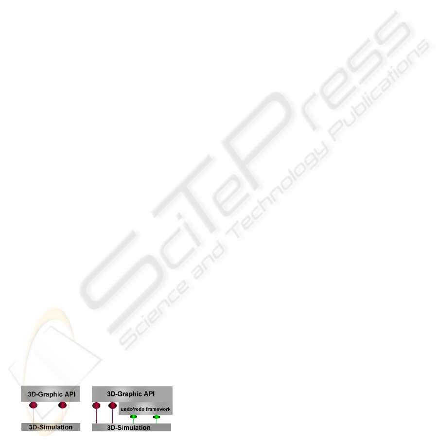
Figure 1: Implementing the undo/redo framework by ex-
tending the 3D graphic API.
Each simulation uses graphic API to visualise the
behaviour of its underlying algorithm or data struc-
ture. Usually, the state changes of the simulated al-
gorithm or data structure are graphically illustrated
by invoking methods of API-objects. The red con-
nections in figure 1 denote these calls. To enable a
straightforward generation of simulations, the imple-
mentation of the undo/redo-framework itself should
be carried out on the API-level, not on the simulation
level. This implies that the framework is to be im-
plemented by extending the API itself. This is illus-
trated by the right image of the figure. Method calls
to the framework, however, are made by the simu-
lation itself (see the green connections in the right
image). Thus, the way a previous state is restored,
is transparent for the simulation. It knows nothing
about how an undo or redo operation is managed in
detail. The only thing a simulation needs to know
is how to make calls to the undo/redo framework,
and when to make them. The simulation is provided
with this knowledge by means of an object that imple-
ments an undo/redo interface, which usually consists
of two methods: undo() and redo(). When to make an
undo/redo-call is determined by the user.
We will now briefly introduce the model-view-
controller design pattern (MVC) (E. Freeman and
Bates, 2004) that we used for the design of our sim-
ulations. Later, we will describe the issues related to
the use of the command pattern and explain why we
decided to use the memento pattern instead.
The MVC describes a powerful architecture for
visual applications which breaks an application into
three independent components: the model, the view
and the controller. The model represents the infor-
mation (the data) of the application; the view cor-
responds to visual components used to visualise the
data; the controller is the interface between the model
and the view. The controller communicates data back
and forth between the model and the view. It is re-
sponsible for transferring changes performed by the
application or the user, between the model and the
view.
When a 3D algorithm visual simulation is imple-
mented according to the MVC-model, it usually con-
sists of a model describing the data used by the al-
gorithm, a view which is the graphical representation
of the data, and a controller. Whenever changes on
the data model are performed, these changes are vi-
sually reflected by changes to the view. When imple-
menting the command design pattern as a basis for
an undo/redo framework each change to the model
must be encapsulated into a command. For each
data-command there should also be a corresponding
view-command that reflects the changes. This means
that for each simulation, we should identify all per-
formed commands and link them to corresponding
visual commands. This would only be possible if
GRAPP 2009 - International Conference on Computer Graphics Theory and Applications
276
we were interested in simulating a limited number
of algorithms. Another issue concerning the use of
the command pattern is that there are visual changes
that do not correspond to any changes on the model.
Consider simulating a red-black-tree (T. Cormen and
Rivest, 2002). Whenever an element is added or re-
moved from the tree, the corresponding visual tree
needs to be laid out again. This is a visual opera-
tion that has no corresponding model-operation. A
third issue related to using the command pattern is
the memory amount required to make animations un-
doable independent of whether the simulation follows
the MVC-model or not. A single animated translation
of an object consists of a large number of transforma-
tion operations, all of which need to be stored as com-
mands in order to enable a later reversal of the anima-
tion. A simulation with a large number of animated
actions can easily lead to a memory overflow. Fur-
thermore, the implementation of the command pat-
tern for a powerful 3D-API can be very costly and
always require using the memento pattern to store all
data needed to undo an operation. The memento pat-
tern on the other hand is easy to implement and allows
a very efficient and memory-friendly implementation.
Therefore, concluding from this observation and from
our own experience, we believe that the memento-
design pattern is the best pattern we can recommend
for designing undo/redo facilities for algorithm simu-
lation systems.
3 DESIGN CONCEPT OF THE
FRAMEWORK
Our framework is generic in that it does not necessi-
tate that the simulations are implemented according to
the MVC-model. If we assumed that simulations are
entirely implemented according to the MVC-model
then we would not need to implement an undo/redo
facility for the view. This is because any changes to
the model are automatically reflected by changes to
the view by the controller. Hence, we will assume that
there is a model and a view which are not necessarily
uncoupled from each other.
We will now introduce the undo/redo design con-
cept of the data model and that of the view separately,
and explain how undo/redo operations of the model
are synchronised with that of the view, and vice versa.
We will also assume that each simulation consists of
several steps, each of which consists of several ac-
tions. The end of each step (i.e. the last action) is an-
notated using any annotation technique supported by
the programming language. The granularity of each
step is left to the simulation designer.
3.1 Model Undo/Redo
When a step, say i is to be reversed, the undo/redo-
manager of the simulation is expected to restore the
(i-1)-th state of the data model. The state of the data
model is defined by the occupancy of its interesting
1
data fields and data structures. Executing step i trans-
fers the (i-1)-th state of the simulation to state i. The
easiest way to implement undo/redo support for the
data model is to store the entire state of the simula-
tion after each step. However saving the entire state is
in many cases not necessary and would violate our re-
quirement of an efficient undo/redo-framework. Sav-
ing the entire state is particularly not necessary, when
a step only causes a partial state change. Our concept
makes sure that only values that have been changed
during the last step are saved. To achieve that, a copy
of each data field is kept temporarily before a step is
executed. Moreover, each step is assigned a unique
id by the undo/redo manager. When a step terminates
the current value of each field is compared to its previ-
ous value. In case of a mismatch, the old value is kept
together with the previous step id as a (key,value)-pair
in a special container managed by the undo/redo man-
ager of the simulation. Thereby ”key” is the previous
step id and ”value” is the old value of the field. If the
value has not changed, nothing is needed to be done.
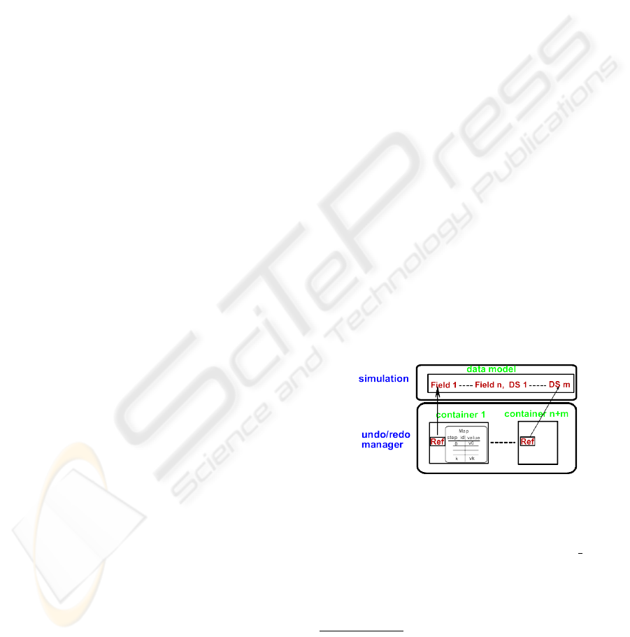
To manage that, the undo/redo manager maintains a
container for each data field or data structure. Each
container maintains a reference to its corresponding
field or data structure as well as a hash map (see fig-
ure 2).
Figure 2: Structure of the undo/redo manager for the data-
model.
If the value of the field has changed during step
i, the map will include the entry (i-1, old value)
consisting of the old value of the field referenced
by the previous step id as a key. Otherwise, there
is no such entry. The undo/redo manager provides
two methods to perform an undo and a redo oper-
1
Interesting data fields are those which are essential for
understanding the algorithm or data structures and are there-
fore subject of visualisation. Some algorithms use tempo-
rary variables. Such variables and variables of loops are
usually not visualised and their previous overridden value
do not need to be restored.
AN EFFICIENT UNDO/REDO-FRAMEWORK FOR THREE-DIMENSIONAL VISUAL SIMULATION OF
ALGORITHMS AND DATA STRUCTURES
277

ation. These are called saveState(step id) and re-
storeState(step id); each of which receives the step
id as a parameter. Invoking saveState is usually per-
formed by the simulation whenever a step terminates,
in which case the recently described procedure is pre-
formed. When the user wants to undo a step, that
is when he clicks on the undo button, restoreState is
called and passed the (step id-1) as a parameter. The
method is implemented in such a manner that each
container is searched for an entry that has the given
step id as a key. If such an entry exists the stored
field value is fetched and assigned to the correspond-
ing field, otherwise, nothing happens. restoreState is
also invoked when an undone step need to be redone.
This is exactly the case when the user clicks on the
redo button.
To incorporate the undo/redo functionality into a
simulation, the simulation is given a reference to an
undo/redo manager. In order to use the manager, the
simulation only needs to invoke saveState at the end
of each step and restoreState whenever the user clicks
on an undo or redo button. Thus, the usage of the
undo/redo manager is very straightforward and sup-
ports the automatic generation of simulations. As
we use hash tables, an undo operation can be accom-
plished in a very efficient way. Thus, the implemen-
tation of the concept is not only memory-friendly but
also highly efficient.
3.2 Visual Undo/Redo
The concept for implementing an undo/redo manager
of the visual part of a simulation is more sophisticated
and requires much more work than is the case with
the data model. Any object-oriented high level 3D
graphic-API such as Java3D (Java3D, ), OpenScene-
Graph (OpenScengraph, ) or Ogre (Ogre, ) consists
of a collection of classes which serve as an interface
to a sophisticated three-dimensional graphics render-
ing system. A 3D application is assembled from a
variety of geometrical and appearance objects speci-
fied in the programming language of the API. A geo-
metrical or an appearance object describes the struc-
ture or the appearance of its corresponding visual ob-
ject respectively. Together, the visual objects of an
application form a hierarchical virtual scene (virtual
universe) called scene graph. The scene graph is a
structure that arranges the logical and often (but not
necessarily) spatial representation of a 3D scene. It
is assembled of a collection of nodes in a graph or
tree structure. Visual changes to the scene graph
are accomplished by performing structural and/or vi-
sual changes to its objects. These changes are then
rendered by the underlying rendering system. Per-
haps the easiest way to keep track of changes to a
scene graph is to clone the entire graph. However
this would violate our requirement, as cloning large
graphs slows the application down and requires a
huge amount of space. Instead, our concept involves
traversing the graph and saving essential information
about its structure that enables the later reconstruc-
tion of the entire graph. Moreover, we have extended
the 3D graphic API and made each interesting object
undoable by letting it implement a special interface.
Like the interface used by the undo/redo manager
of the model, this interface includes only two meth-
ods saveState(step id) and restoreState(step id). We
adopted the same undo/redo concept of the model to
implement these methods. That means that each ob-
ject manages its state changes by itself and uses its
own undo/redo manager. Whenever a step is com-
pletely executed, the visual undo/redo manager tra-
verses the entire scene graph, stores structural infor-
mation and requires each object in the graph to store
its current state by invoking saveState. While the state
changes of each object are preserved in its own con-
tainers the structural information for each step that en-
able the reconstruction of the scene graph are kept in
special data structure keyed by the step id. Whenever
a step is to be reversed the associated scene graph
is reconstructed using the corresponding data struc-
ture. The entire graph is then traversed and each ob-
ject is enforced to restore its state by calling its own
restoreState-method. This has proven to be a very
efficient way to implement visual undo. A global
undo/redo manager makes sure that each call on the
model undo/redo manager is accompanied by a call
on the visual undo/redo with the same step id, and
vice versa.
4 IMPLEMENTATION
We used Java as programming language and Java3D
as 3D-API for developing our simulations. The im-
plementation of the undo/redo interfaces for the vi-
sual part of the framework has required much more
work, as a large number of Java3D classes needed to
be extended.
Nevertheless, with our framework we are now
able to implement undo/redo functionality to any kind
of visual simulations implemented in Java and Java3D
at a minimal effort. The framework has been incorpo-
rated into 3D-VISIAN (Baker and Milanovic, 2008)
and has been tested extensively. 3D-VISIAN (see
figure 3) is a platform for 3D visual simulation and
animation of algorithms developed at our Institute of
Computer Graphics.
GRAPP 2009 - International Conference on Computer Graphics Theory and Applications
278
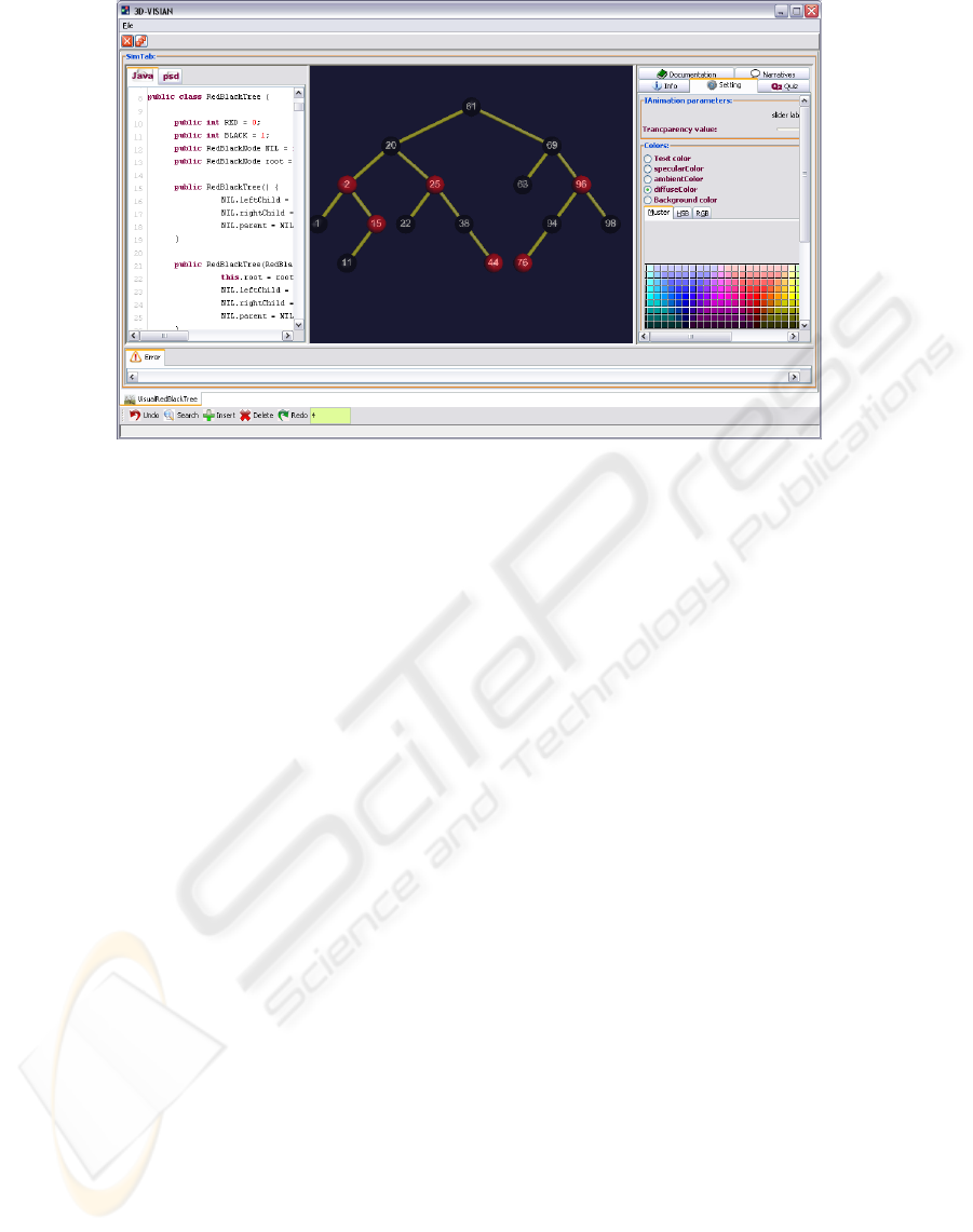
Figure 3: Red-Black tree simulation in 3D-VISIAN.
5 CONCLUSIONS AND
EVALUATION
In this work we presented an efficient undo/redo
framework that enables us to reverse and repeat ar-
bitrary actions carried out by any visual simulation
implemented in Java and Java3D. The framework is
very straightforward to use, and supports a seamless
automatic generation of simulations and satisfies the
earlier mentioned demand. The effort needed to use
the framework in a simulation is minimal, the mem-
ory usage is minimal as well, and actions are undone
and redone very fast. The introduced concept for the
visual undo is scene-graph-based and can be used for
any scene-graph-based 3D graphics API. The usage
of the extended API is not confined to algorithm visu-
alisation. It can also be used for any 3D-application
(games, scientific visulisation, visual simualtion, etc.)
whenever undo/redo is desired.
However, it has some disadvantages. Whenever
a new version of the API is released, all new classes
of the API need to be extended accordingly. Imple-
mentation changes in a new release such as deprecat-
ing methods might require a slight adaption of some
classes.
REFERENCES
Baker, A. A. and Kappes, S. (2008). Three-dimensional
static animation of computation-intensive 3d-
algorithms. IEEE-CITE08.
Baker, A. A. and Milanovic, B. (2008). A universal exten-
sible architecture for algorithm visualisation systems.
IEEE-CITE08.
E. Freeman, E. Freeman, K. S. and Bates, B. (2004). Head
First Design Patterns. Oreilly.
E. Gamma, R. Helm, R. and Vlissides, J. (1994). Design
Patterns: Elements of Reusable Object-Oriented Soft-
ware. Addison-Wesley.
J. Archer, R. C. and Schneider, F. B. (1984). User recovery
and reversal in interactive systems.
Java3D. https://java3d.dev.java.net. Sun Microstems.
Ogre. http://www.ogre3d.org/.
OpenScengraph. http://www.openscenegraph.org/projects/osg.
Prakash and Knister, J. (1994). A framework for undoing
actions in collaborative systems. ACM.
Roessling, G. (2002). Animal-farm: An extensible frame-
work for algorithm visualization. In Ph.D. Thesis.
Universitaet Siegen.
S. Douglas, D. M. and Hundhausen, C. (1996). Exploring
human visualization of computer algorithms. Graph-
ics Interface ’96.
Stasko, J. and Badre, A. (1993). Do algorithm animations
assist learning? an empirical study and analysis. ACM
INTERCHI.
T. Cormen, D. College, C. L. and Rivest, R. (2002). In-
troduction to Algorithms. McGraw-Hill Higher Edu-
cation, Massachusetts Institute of Technology, second
edition edition.
T. Naps, G. R. and et al. (2003). Exploring the role of visu-
alization and engagement in computer science educa-
tion. ACM INTERCHI.
AN EFFICIENT UNDO/REDO-FRAMEWORK FOR THREE-DIMENSIONAL VISUAL SIMULATION OF
ALGORITHMS AND DATA STRUCTURES
279
